EP1347811B1 - Toy device using through-the-body communication - Google Patents
Toy device using through-the-body communication Download PDFInfo
- Publication number
- EP1347811B1 EP1347811B1 EP02705849A EP02705849A EP1347811B1 EP 1347811 B1 EP1347811 B1 EP 1347811B1 EP 02705849 A EP02705849 A EP 02705849A EP 02705849 A EP02705849 A EP 02705849A EP 1347811 B1 EP1347811 B1 EP 1347811B1
- Authority
- EP
- European Patent Office
- Prior art keywords
- user
- signal
- radio frequency
- circuit
- toy
- Prior art date
- Legal status (The legal status is an assumption and is not a legal conclusion. Google has not performed a legal analysis and makes no representation as to the accuracy of the status listed.)
- Expired - Lifetime
Links
- 238000004891 communication Methods 0.000 title claims description 10
- 210000000707 wrist Anatomy 0.000 claims description 29
- 230000008878 coupling Effects 0.000 claims description 5
- 238000010168 coupling process Methods 0.000 claims description 5
- 238000005859 coupling reaction Methods 0.000 claims description 5
- 230000000644 propagated effect Effects 0.000 claims 1
- 210000003811 finger Anatomy 0.000 description 6
- 230000033001 locomotion Effects 0.000 description 5
- 238000004519 manufacturing process Methods 0.000 description 3
- 238000000034 method Methods 0.000 description 3
- 206010011878 Deafness Diseases 0.000 description 2
- 238000013475 authorization Methods 0.000 description 2
- 238000010586 diagram Methods 0.000 description 2
- 239000004744 fabric Substances 0.000 description 2
- 238000012986 modification Methods 0.000 description 2
- 230000004048 modification Effects 0.000 description 2
- 230000001902 propagating effect Effects 0.000 description 2
- 230000004044 response Effects 0.000 description 2
- 210000003813 thumb Anatomy 0.000 description 2
- 241001465754 Metazoa Species 0.000 description 1
- 230000003213 activating effect Effects 0.000 description 1
- 230000004913 activation Effects 0.000 description 1
- 238000013479 data entry Methods 0.000 description 1
- 230000000694 effects Effects 0.000 description 1
- 210000001145 finger joint Anatomy 0.000 description 1
- 230000006870 function Effects 0.000 description 1
- 210000004247 hand Anatomy 0.000 description 1
- 230000007246 mechanism Effects 0.000 description 1
- 238000012544 monitoring process Methods 0.000 description 1
- 230000003287 optical effect Effects 0.000 description 1
- 230000008569 process Effects 0.000 description 1
- 238000012545 processing Methods 0.000 description 1
- 230000011664 signaling Effects 0.000 description 1
- 238000007920 subcutaneous administration Methods 0.000 description 1
- 210000002435 tendon Anatomy 0.000 description 1
- 238000013519 translation Methods 0.000 description 1
Images

Classifications
-
- A—HUMAN NECESSITIES
- A61—MEDICAL OR VETERINARY SCIENCE; HYGIENE
- A61B—DIAGNOSIS; SURGERY; IDENTIFICATION
- A61B5/00—Measuring for diagnostic purposes; Identification of persons
- A61B5/0002—Remote monitoring of patients using telemetry, e.g. transmission of vital signals via a communication network
- A61B5/0026—Remote monitoring of patients using telemetry, e.g. transmission of vital signals via a communication network characterised by the transmission medium
- A61B5/0028—Body tissue as transmission medium, i.e. transmission systems where the medium is the human body
-
- A—HUMAN NECESSITIES
- A63—SPORTS; GAMES; AMUSEMENTS
- A63H—TOYS, e.g. TOPS, DOLLS, HOOPS OR BUILDING BLOCKS
- A63H30/00—Remote-control arrangements specially adapted for toys, e.g. for toy vehicles
- A63H30/02—Electrical arrangements
- A63H30/04—Electrical arrangements using wireless transmission
Definitions
- This invention relates generally to toys and particularly to toys operative in a communications mode.
- Toys which are capable of communication are well known in the art and have been provided in a variety of formats and designs.
- Many toys include a plurality of user operated keys or buttons which facilitate inputting and identifying code opening the operation of the device to the user.
- Still other toys employ locks or closures which restrict access of operation of the toy to a key holder or the like.
- input devices in the form of gloves or other apparatus are provided with a number of signaling devices which are capable of use in remotely controlling a game or toy apparatus.
- U.S. Patent 5,488,362 issued to Ullman et al. sets forth an APPARATUS FOR CONTROLLING A VIDEO GAME having a glove-like attachment worn by an operator.
- the glove includes a wrist portion having parallel conductive contacts. Once set of contacts is connected to a signal generator which produces control signals for characters in a video game. The second set of contacts is connected to the video game. Placing the hand at an angle selectively connects the contacts sending the desired direction control signal to the game.
- U.S. Patent 5,212,372 issued to Quick et al. sets forth a PORTABLE TRANSACTION TERMINAL FOR OPTICAL AND KEY ENTRY OF DATA WITHOUT KEYBOARDS AND MANUALLY ACTUATED SCANNERS in which a glove is worn an operator having a plurality of sensors positioned upon the finger and thumb portions of the glove. The sensors are operative in response to movement and flexing of the wearer's fingers and thumb and produce signals which are coupled to a communication device.
- U.S. Patent 4,414,537 issued to Grimes sets forth a DIGITAL DATA ENTRY GLOVE INTERFACE DEVICE for translating discreet hand positions into electrical signals representing Alpha-numeric characters.
- the interface includes a glove having sensors positioned with respect to the hand for detecting the flex of finger joints and sensors for detecting the contact between various portions of the hand. Additional sensors detect the movement of the hand with respect to the gravitational vector.
- U.S. Patent 5,537,102 issued to Pinnow sets forth an APPARATUS AND METHOD FOR A SYSTEM CAPABLE OF REMOTELY VALIDATING THE IDENTITY OF AN INDIVIDUAL AND THEIR LOCATION having a wrist worn device which electronically generates a sequence of Pseudorandom numbers that seizes functioning if the band is cut or otherwise opened to detach the device from the individual.
- a monitoring system remotely validates the continued wearing of the apparatus by the user and allows the wearer to be located remotely.
- U.S. Patent 4,063,410 issued to Welling sets forth a DIGITAL WATCH INCLUDING A SIGNAL TRANSMITTER for selective activation of a remote electronic circuit.
- the wristwatch includes a time of day readout encased in a housing supported by the wrist band. Within the watch housing, time of day display and a signal transmitter are operatively coupled.
- a receiving station is provided with apparatus for remotely responding to the transmitted signal from the watch to activate an electronic circuit such as a burglar alarm or the like.
- U.S. Patent 3,937,004 issued to Natori et al. sets forth a PORTABLE MINIATURE TYPE INFORMATION TREATING DEVICE including an electronic time piece used as a pager watch and having a speaker for emitting an alarm signal at a preset time.
- the circuit also includes an external call signal responsive to incoming electromagnetic waves.
- U.S. Patent 5,014,040 issued to Weaver et al. sets forth a PERSONAL LOCATOR TRANSMITTER adapted to be worn on the wrist and having the size and appearance of a conventional wrist watch.
- the transmitter is provided with a programmable memory, a transmitter controlled by the memory and an antenna for reliably radiating signals from the transmitter and an automatic alarm actuated by an attempt to remove the unit from the wrist of the wearer.
- U.S. Patent 5,047,952 issued to Kramer et al. sets forth a COMMUNICATION SYSTEM FOR DEAF, DEAF-BLIND OR NONVOCAL INDIVIDUALS USING INSTRUMENTED GLOVE the glove supports a plurality of strain gage sensors which respond to flexing movements of the hands. Signals from the circuitry within the glove responsive to the strain gage outputs are amplified and digitized and applied to a computer which includes software for recognition of the hand positions and hand states.
- U.S. Patent 5,648,753 issued to Martin sets forth an INTERCHANGEABLE SOUND EFFECT DEVICE which includes means for playing digitally recorded sounds in the form of interchangeable cartridges.
- the device is designed for use with entertainment and educational-type products such as toys, dolls, figurines, books and instructional guides.
- the device utilizes an infrared receiver.
- EP-A-0 991 026 teaches an authorisation control system for preventing unauthorised use of devices like fire arms, cars or other precious or dangerous devices.
- the authorisation check is performed with secret personal data carried by the person and some data stored in digital form in the device.
- the data is transferred automatically from the person into the device's data processing device when an authorised person wants to use the device.
- the data interface comprises capacitive coupling means with the human body serving as carrier of the information stream.
- FIG. 1 sets forth a perspective view of a toy device constructed in accordance with the present invention and generally referenced by numeral 10.
- Toy device 10 includes a wrist unit 11, a controlled device 12 and a controlled toy 13.
- a user 20 is shown wearing wrist unit 11 upon arm 21 while activating device 12 using finger 23 of arm 22.
- Controlled device 12 includes a housing supporting a contact 30 and a plurality of user operator keys 31.
- Device 12 further includes an infrared transmitter 32.
- Controlled toy 13 may be fabricated in accordance with the desired theme or application of the present invention system. In the example shown in Figure 1, control toy 13 is a small animal figure having an infrared sensor 33.
- Controlled toy 13 includes internal apparatus (not shown) responsive to sensor 33 in accordance with conventional fabrication techniques.
- wrist unit 11 produces a coded signal which is coupled to arm 21 of user 20.
- Body 24 of user 20 provides a medium through which the signal outputted by wrist unit 11 propagate.
- the ability of human body to carry electrical signals such as radio frequency signals throughout the body is well known and well established in the art. Suffice it to note here that electrical signals applied by wrist unit 11 to arm 21 appear generally throughout body 24.
- electrical signals applied by wrist unit 11 to arm 21 appear generally throughout body 24.
- the portion of coupled energy from wrist unit 11 which propagates through arm 21 across body 24 and downwardly through arm 22 to eventually reach finger 13.
- As the user touches contact 30 with finger 23 a small portion of the signal produced by wrist unit 11 and propagating through body 24 and arm 22 is coupled to contact 30.
- device 12 responds to the signal coupled to contact 30 to verify that finger 23 is indeed a body portion belonging to the wearer of wrist unit 11.
- the encoded signal produced by wrist unit 11 uniquely identifies user 20 to device 12.
- wrist unit 11 produces a radio frequency signal having an encoded identifier thereon.
- device 12 includes a decoding unit which reads the coded indicator upon the signal received at contact 30 and compares it to a stored reference code to determine whether or not keys 31 of device 12 are to operable in response to user 20.
- Control toy 13 is a conventional infrared remote control toy which is provided as an illustration of the use of the present invention toy device.
- a simple remote control apparatus operable between a remote controlling device 12 and a controlled toy 13 is operable solely by user 20 while wearing wrist unit 11.
- FIG. 2 sets forth a section view of wrist unit 11.
- Wrist unit 11 includes a housing 40 within which a circuit 41 is supported.
- An external contact 43 is positioned upon the underside of housing 40 and is coupled to circuit 41 by a connector 42.
- a conventional wrist band 44 is secured to housing 40 in a conventional attachment (not shown).
- Band 44 is used to secure wrist unit 11 to a wearer's wrist in the manner shown in Figure 1.
- Band 44 thus includes a cooper ting pair of hook-and-loop fabric attachment pads 49. It will be apparent however, that alternative fastening apparatus such as snap fasteners or buckles or the like may be utilized in place of hook-and-loop fabric attachment pads 49 without departing from the spirit and scope of the present invention.
- circuit 41 produces an output signal such as a radio frequency signal which is coupled to contact 43 by connector 42.
- This signal is preferably encoded with an identifying code recognizable by the cooperating device such as devices 12 and 34 (seen in Figure 1).
- Contact 43 is positioned against the wearer's skin to provide optimal signal coupling to the wearer's body and to allow the use of the wearer's body as a propagating medium.
- Circuit 41 is set forth below in Figure 3 in greater detail. However, suffice it to note here that circuit 41 is a battery-powered microprocessor based circuit suitable for producing a radio frequency signal of sufficient strength to transmit energy through the wearer's body.
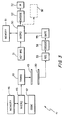
- FIG. 3 sets forth a block diagram of the present invention toy device.
- Toy device 10 includes a circuit 41 supported within wrist unit 11 in the manner set forth above in Figure 2.
- circuit 41 includes a microprocessor 45 having an associated memory 46.
- a code generating circuit 47 is also coupled to microprocessor 45.
- Microprocessor 45 is operatively coupled to a transmitting circuit 48 which in turn is coupled to contact 43.
- Figure 3 further shows the operative circuitry within device 12 set forth above in Figure 1.
- Device 12 includes a microprocessor 50 having an associated memory 51 and a keyboard 31 coupled thereto.
- a contact 30 which, as is better seen in Figure 1, is supported upon device 12 is coupled to a receiver 53 which in turn is coupled to a decoding circuit 54.
- Decoding circuit 54 controls a gate circuit 55 which provides and enabling signal to microprocessor 50.
- the output to microprocessor 50 is coupled to an infrared signal encoder 52 which in turn is coupled to an infrared transmitter 32.
- microprocessor 45 operating in accordance with the stored instruction set or program within memory 46, receives a coded number sequence from code circuit 47 which is applied to the modulating input of transmitter 48.
- Transmitter 48 provides an output signal such as a radio frequency signal having the code received from code circuit 47 modulated thereon.
- contact 43 is energized by transmitter 48 and, as is described above, is operatively coupled to the user's body.
- a receiving function is carried forward as contact 30 is touched by user 20 (seen in Figure 1) coupling a portion of the energy within the user's body received from transmitter 48 and contact 43.
- the coupled signal and its modulated code are applied to a receiver 53 which recovers the coded information therefrom and applies it to decode circuit 54.
- Decode circuit 54 compares the coded signal to a stored reference signal and if a correct match is found energizes gate 55.
- Gate 55 when energized produces an enabling signal to microprocessor 50 causing microprocessor 50 to activate encoder 52 which in turn drives infrared output device 32.
- microprocessor 50 does not receive an enabling signal and keyboard inputs at keyboard 31 are not operatively coupled to encoder 52 and infrared transmitter 32. As a result, device 12 does not respond to the user.
- circuit shown in Figure 3 for device 12 is substantially the same as the internal circuit within device 34 with the difference being found in the replacement of encoder 52 and infrared transmitting device 32 with a conventional sound circuit 38 (shown in dashed-line).
- the circuit within device 34 (seen in Figure 1) is identical to the circuit shown in Figure 3 as found within device 12.
- Figure 4 sets forth a perspective view of an alternate embodiment of the present invention.
- the embodiment shown in Figure 4 differs from the previously described embodiment in that it is configured to be handheld as opposed to worn upon the users wrist.
- the embodiment shown in Figure 4 will be understood to be identical to the embodiment described above and will be understood to include circuit 41 operable in the same manner as described above within wrist unit 11.
- a handheld unit 60 includes a housing 61 which supports circuit 41 (seen in Figure 3) together with a body contact 62.
- the user hold unit 60 such that contact 62 touches the user's body such as the palm of a hand or the like allowing the signal to propagate from unit 60 through the user's body.
- the encoded signal is produced by a wrist unit which is worn in much the same way as a conventional watch.
Landscapes
- Life Sciences & Earth Sciences (AREA)
- Engineering & Computer Science (AREA)
- Health & Medical Sciences (AREA)
- Computer Networks & Wireless Communication (AREA)
- Heart & Thoracic Surgery (AREA)
- Biophysics (AREA)
- Pathology (AREA)
- Biomedical Technology (AREA)
- Physics & Mathematics (AREA)
- Medical Informatics (AREA)
- Molecular Biology (AREA)
- Surgery (AREA)
- Animal Behavior & Ethology (AREA)
- General Health & Medical Sciences (AREA)
- Public Health (AREA)
- Veterinary Medicine (AREA)
- Toys (AREA)
Description
- This invention relates generally to toys and particularly to toys operative in a communications mode.
- Toys which are capable of communication are well known in the art and have been provided in a variety of formats and designs. Many toys include a plurality of user operated keys or buttons which facilitate inputting and identifying code opening the operation of the device to the user. Still other toys employ locks or closures which restrict access of operation of the toy to a key holder or the like.
- In a related art, input devices in the form of gloves or other apparatus are provided with a number of signaling devices which are capable of use in remotely controlling a game or toy apparatus. For example, U.S. Patent 5,488,362 issued to Ullman et al. sets forth an APPARATUS FOR CONTROLLING A VIDEO GAME having a glove-like attachment worn by an operator. The glove includes a wrist portion having parallel conductive contacts. Once set of contacts is connected to a signal generator which produces control signals for characters in a video game. The second set of contacts is connected to the video game. Placing the hand at an angle selectively connects the contacts sending the desired direction control signal to the game.
- U.S. Patent 5,212,372 issued to Quick et al. sets forth a PORTABLE TRANSACTION TERMINAL FOR OPTICAL AND KEY ENTRY OF DATA WITHOUT KEYBOARDS AND MANUALLY ACTUATED SCANNERS in which a glove is worn an operator having a plurality of sensors positioned upon the finger and thumb portions of the glove. The sensors are operative in response to movement and flexing of the wearer's fingers and thumb and produce signals which are coupled to a communication device.
- U.S. Patent 4,414,537 issued to Grimes sets forth a DIGITAL DATA ENTRY GLOVE INTERFACE DEVICE for translating discreet hand positions into electrical signals representing Alpha-numeric characters. The interface includes a glove having sensors positioned with respect to the hand for detecting the flex of finger joints and sensors for detecting the contact between various portions of the hand. Additional sensors detect the movement of the hand with respect to the gravitational vector.
- U.S. Patent 5,537,102 issued to Pinnow sets forth an APPARATUS AND METHOD FOR A SYSTEM CAPABLE OF REMOTELY VALIDATING THE IDENTITY OF AN INDIVIDUAL AND THEIR LOCATION having a wrist worn device which electronically generates a sequence of Pseudorandom numbers that seizes functioning if the band is cut or otherwise opened to detach the device from the individual. A monitoring system remotely validates the continued wearing of the apparatus by the user and allows the wearer to be located remotely.
- U.S. Patent 4,063,410 issued to Welling sets forth a DIGITAL WATCH INCLUDING A SIGNAL TRANSMITTER for selective activation of a remote electronic circuit. The wristwatch includes a time of day readout encased in a housing supported by the wrist band. Within the watch housing, time of day display and a signal transmitter are operatively coupled. A receiving station is provided with apparatus for remotely responding to the transmitted signal from the watch to activate an electronic circuit such as a burglar alarm or the like.
- U.S. Patent 3,937,004 issued to Natori et al. sets forth a PORTABLE MINIATURE TYPE INFORMATION TREATING DEVICE including an electronic time piece used as a pager watch and having a speaker for emitting an alarm signal at a preset time. The circuit also includes an external call signal responsive to incoming electromagnetic waves.
- U.S. Patent 5,014,040 issued to Weaver et al. sets forth a PERSONAL LOCATOR TRANSMITTER adapted to be worn on the wrist and having the size and appearance of a conventional wrist watch. The transmitter is provided with a programmable memory, a transmitter controlled by the memory and an antenna for reliably radiating signals from the transmitter and an automatic alarm actuated by an attempt to remove the unit from the wrist of the wearer.
- U.S. Patent 5,047,952 issued to Kramer et al. sets forth a COMMUNICATION SYSTEM FOR DEAF, DEAF-BLIND OR NONVOCAL INDIVIDUALS USING INSTRUMENTED GLOVE the glove supports a plurality of strain gage sensors which respond to flexing movements of the hands. Signals from the circuitry within the glove responsive to the strain gage outputs are amplified and digitized and applied to a computer which includes software for recognition of the hand positions and hand states.
- U.S. Patent 5,648,753 issued to Martin sets forth an INTERCHANGEABLE SOUND EFFECT DEVICE which includes means for playing digitally recorded sounds in the form of interchangeable cartridges. The device is designed for use with entertainment and educational-type products such as toys, dolls, figurines, books and instructional guides. The device utilizes an infrared receiver.
- U.S. Patent 5,818,359 issued to Beach sets forth a PROCESS AND APPARATUS FOR COMPUTERIZING TRANSLATION OF MOTION OF SUBCUTANEOUS BODY PARTS useful in tracking movement of body parts such as tendons within the carpal tunnel of the wrist.
- EP-A-0 991 026 teaches an authorisation control system for preventing unauthorised use of devices like fire arms, cars or other precious or dangerous devices. The authorisation check is performed with secret personal data carried by the person and some data stored in digital form in the device. The data is transferred automatically from the person into the device's data processing device when an authorised person wants to use the device. The data interface comprises capacitive coupling means with the human body serving as carrier of the information stream.
- While the foregoing described prior art devices have to some extent improved the art and have in some instances enjoyed commercial success, there remains nonetheless a continuing need in the art for evermore improved, interesting and amusing toy products which utilize various communication mechanisms.
- Accordingly, it is a general object of the present invention to provide an improved toy device. It is a more particular object of the present invention to provide an improved toy device which utilizes through-the-body communication.
- In accordance with the present invention there is provided an apparatus using through-the-body communication and having the features of claim 1.
- The features of the present invention, which are believed to be novel, are set forth with particularity in the appended claims. The invention, together with further objects and advantages thereof, may best be understood by reference to the following description taken in conjunction with the accompanying drawings, in the several figures of which like reference numerals identify like elements and in which:
- Figure 1 sets forth a perspective view of a toy device constructed in accordance with the present invention operated by a child user;
- Figure 2 sets forth a section view of the wrist-worn portion of the present invention toy device;
- Figure 3 sets forth a block diagram of the operative circuitry within the present invention toy device;
- Figure 4 sets forth a perspective view of an alternate embodiment of the present invention toy device.
- Figure 1 sets forth a perspective view of a toy device constructed in accordance with the present invention and generally referenced by
numeral 10.Toy device 10 includes a wrist unit 11, a controlleddevice 12 and a controlledtoy 13. Auser 20 is shown wearing wrist unit 11 uponarm 21 while activatingdevice 12 usingfinger 23 ofarm 22. Controlleddevice 12 includes a housing supporting acontact 30 and a plurality ofuser operator keys 31.Device 12 further includes aninfrared transmitter 32. Controlledtoy 13 may be fabricated in accordance with the desired theme or application of the present invention system. In the example shown in Figure 1,control toy 13 is a small animal figure having aninfrared sensor 33. Controlledtoy 13 includes internal apparatus (not shown) responsive tosensor 33 in accordance with conventional fabrication techniques. - In operation, and by means described below in greater detail, wrist unit 11 produces a coded signal which is coupled to
arm 21 ofuser 20.Body 24 ofuser 20 provides a medium through which the signal outputted by wrist unit 11 propagate. The ability of human body to carry electrical signals such as radio frequency signals throughout the body is well known and well established in the art. Suffice it to note here that electrical signals applied by wrist unit 11 toarm 21 appear generally throughoutbody 24. Of interest with respect to the present invention, is the portion of coupled energy from wrist unit 11 which propagates througharm 21 acrossbody 24 and downwardly througharm 22 to eventually reachfinger 13. As the user touches contact 30 withfinger 23, a small portion of the signal produced by wrist unit 11 and propagating throughbody 24 andarm 22 is coupled to contact 30. By means set forth below in greater detail,device 12 responds to the signal coupled to contact 30 to verify thatfinger 23 is indeed a body portion belonging to the wearer of wrist unit 11. In other words, the encoded signal produced by wrist unit 11 uniquely identifiesuser 20 todevice 12. In the preferred fabrication of the present invention, wrist unit 11 produces a radio frequency signal having an encoded identifier thereon. Further in the preferred fabrication of the present invention,device 12 includes a decoding unit which reads the coded indicator upon the signal received atcontact 30 and compares it to a stored reference code to determine whether or notkeys 31 ofdevice 12 are to operable in response touser 20. -
Control toy 13 is a conventional infrared remote control toy which is provided as an illustration of the use of the present invention toy device. In the example shown in Figure 1 and provided bydevice 12, a simple remote control apparatus operable between aremote controlling device 12 and a controlledtoy 13 is operable solely byuser 20 while wearing wrist unit 11. - Figure 2 sets forth a section view of wrist unit 11. Wrist unit 11 includes a housing 40 within which a
circuit 41 is supported. Anexternal contact 43 is positioned upon the underside of housing 40 and is coupled tocircuit 41 by aconnector 42. Aconventional wrist band 44 is secured to housing 40 in a conventional attachment (not shown).Band 44 is used to secure wrist unit 11 to a wearer's wrist in the manner shown in Figure 1.Band 44 thus includes a cooper ting pair of hook-and-loopfabric attachment pads 49. It will be apparent however, that alternative fastening apparatus such as snap fasteners or buckles or the like may be utilized in place of hook-and-loopfabric attachment pads 49 without departing from the spirit and scope of the present invention. - In operation,
circuit 41 produces an output signal such as a radio frequency signal which is coupled to contact 43 byconnector 42. This signal is preferably encoded with an identifying code recognizable by the cooperating device such asdevices 12 and 34 (seen in Figure 1).Contact 43 is positioned against the wearer's skin to provide optimal signal coupling to the wearer's body and to allow the use of the wearer's body as a propagating medium.Circuit 41 is set forth below in Figure 3 in greater detail. However, suffice it to note here thatcircuit 41 is a battery-powered microprocessor based circuit suitable for producing a radio frequency signal of sufficient strength to transmit energy through the wearer's body. - Figure 3 sets forth a block diagram of the present invention toy device.
Toy device 10 includes acircuit 41 supported within wrist unit 11 in the manner set forth above in Figure 2. Thus,circuit 41 includes amicroprocessor 45 having an associatedmemory 46. Acode generating circuit 47 is also coupled tomicroprocessor 45.Microprocessor 45 is operatively coupled to a transmittingcircuit 48 which in turn is coupled to contact 43. - Figure 3 further shows the operative circuitry within
device 12 set forth above in Figure 1.Device 12 includes amicroprocessor 50 having an associatedmemory 51 and akeyboard 31 coupled thereto. Acontact 30 which, as is better seen in Figure 1, is supported upondevice 12 is coupled to areceiver 53 which in turn is coupled to adecoding circuit 54. Decodingcircuit 54 controls agate circuit 55 which provides and enabling signal tomicroprocessor 50. The output tomicroprocessor 50 is coupled to aninfrared signal encoder 52 which in turn is coupled to aninfrared transmitter 32. - In operation,
microprocessor 45 operating in accordance with the stored instruction set or program withinmemory 46, receives a coded number sequence fromcode circuit 47 which is applied to the modulating input oftransmitter 48.Transmitter 48 provides an output signal such as a radio frequency signal having the code received fromcode circuit 47 modulated thereon. Correspondingly, contact 43 is energized bytransmitter 48 and, as is described above, is operatively coupled to the user's body. - At
device 12, a receiving function is carried forward ascontact 30 is touched by user 20 (seen in Figure 1) coupling a portion of the energy within the user's body received fromtransmitter 48 andcontact 43. The coupled signal and its modulated code are applied to areceiver 53 which recovers the coded information therefrom and applies it to decodecircuit 54.Decode circuit 54 compares the coded signal to a stored reference signal and if a correct match is found energizesgate 55.Gate 55 when energized produces an enabling signal tomicroprocessor 50 causingmicroprocessor 50 to activateencoder 52 which in turn drivesinfrared output device 32. - If however the coded signal received by
decode circuit 54 does not match the stored reference signal,gate 55 is not enabled. Accordingly,microprocessor 50 does not receive an enabling signal and keyboard inputs atkeyboard 31 are not operatively coupled toencoder 52 andinfrared transmitter 32. As a result,device 12 does not respond to the user. - The circuit shown in Figure 3 for
device 12 is substantially the same as the internal circuit within device 34 with the difference being found in the replacement ofencoder 52 andinfrared transmitting device 32 with a conventional sound circuit 38 (shown in dashed-line). In all other respects, the circuit within device 34 (seen in Figure 1) is identical to the circuit shown in Figure 3 as found withindevice 12. - Figure 4 sets forth a perspective view of an alternate embodiment of the present invention. The embodiment shown in Figure 4 differs from the previously described embodiment in that it is configured to be handheld as opposed to worn upon the users wrist. In all other respects however, the embodiment shown in Figure 4 will be understood to be identical to the embodiment described above and will be understood to include
circuit 41 operable in the same manner as described above within wrist unit 11. Thus, ahandheld unit 60 includes ahousing 61 which supports circuit 41 (seen in Figure 3) together with abody contact 62. As seen in Figure 4, theuser hold unit 60 such thatcontact 62 touches the user's body such as the palm of a hand or the like allowing the signal to propagate fromunit 60 through the user's body. - What has been shown is a toy device using through-the-body communication to activate a cooperating toy or other device through the propagation of an identifying encoded signal through the user's body. The encoded signal is produced by a wrist unit which is worn in much the same way as a conventional watch.
- While particular embodiments of the invention have been shown and described, it will be obvious to those skilled in the art that changes and modifications may be made without departing from the invention in its broader aspects. Therefore, the aim in the appended claims is to cover all such changes and modifications as fall within the scope of the invention.
Claims (4)
- An apparatus using through-the-body communication comprising:• a radio frequency transmitter (41) having means (47, 48) for producing an encoded radio frequency signal and having means (43, 62) for coupling said signal to a user's body;• a radio frequency receiver having means (30, 53, 55) for receiving said radio frequency signal when touched by a user (20) and for producing an enable signal; and• a device (12) having said radio frequency receiver therein having operating means (31) responsive to said enable signal; and• a housing (40, 61) supporting said radio frequency transmitter (41) such that said means (43, 62) for coupling is in contact with a user's body;• said radio frequency signal being propagated through the body of a user;characterised by• said device being formed by a remote control device (12) and• further comprising a toy (13) which is controllable by means of said remote control device (12).
- The apparatus set forth in claim 1,
wherein said operating means are formed by a keyboard (31) of said remote control device (12). - The apparatus set forth in claim 1 or 2,
wherein said housing (40) is a wrist unit (11) having means (44, 49) for being worn upon a user's wrist. - The apparatus set forth in claim 1 or 2,
wherein said housing (64) is configured to be held in a user's hand.
Applications Claiming Priority (3)
| Application Number | Priority Date | Filing Date | Title |
|---|---|---|---|
| US791014 | 2001-02-22 | ||
| US09/791,014 US6422911B1 (en) | 2001-02-22 | 2001-02-22 | Toy device using through-the-body communication |
| PCT/US2002/001490 WO2002068078A1 (en) | 2001-02-22 | 2002-01-17 | Toy device using through-the-body communication |
Publications (3)
| Publication Number | Publication Date |
|---|---|
| EP1347811A1 EP1347811A1 (en) | 2003-10-01 |
| EP1347811A4 EP1347811A4 (en) | 2004-12-15 |
| EP1347811B1 true EP1347811B1 (en) | 2006-06-14 |
Family
ID=25152398
Family Applications (1)
| Application Number | Title | Priority Date | Filing Date |
|---|---|---|---|
| EP02705849A Expired - Lifetime EP1347811B1 (en) | 2001-02-22 | 2002-01-17 | Toy device using through-the-body communication |
Country Status (7)
| Country | Link |
|---|---|
| US (1) | US6422911B1 (en) |
| EP (1) | EP1347811B1 (en) |
| AU (1) | AU2002239972B2 (en) |
| CA (1) | CA2425518A1 (en) |
| DE (1) | DE60212325T2 (en) |
| MX (1) | MXPA03003051A (en) |
| WO (1) | WO2002068078A1 (en) |
Families Citing this family (9)
| Publication number | Priority date | Publication date | Assignee | Title |
|---|---|---|---|---|
| TW572767B (en) * | 2001-06-19 | 2004-01-21 | Winbond Electronics Corp | Interactive toy |
| US7114822B2 (en) * | 2004-11-12 | 2006-10-03 | Bbc International, Ltd. | Article of footwear with remote sound activating unit |
| US20070158911A1 (en) * | 2005-11-07 | 2007-07-12 | Torre Gabriel D L | Interactive role-play toy apparatus |
| US20080293465A1 (en) * | 2007-05-25 | 2008-11-27 | Hong Chang | Video interaction device for a whole-body sport game |
| DE102007042704A1 (en) * | 2007-09-07 | 2009-03-12 | Kleinkunst aus dem Erzgebirge Müller GmbH | Erzgebirge handicraft-type decoration article e.g. flying buttress, operating method, involves actuating electrical component e.g. electrical drive, and acoustic component i.e. electronic loudspeaker, of article using short-range radio |
| US9144746B2 (en) | 2010-08-20 | 2015-09-29 | Mattel, Inc. | Toy with locating feature |
| GB2513900B (en) * | 2013-05-10 | 2015-06-03 | G4S Monitoring Technologies Ltd | Person identification system |
| US10255422B1 (en) | 2014-09-15 | 2019-04-09 | Apple Inc. | Identity proxy for access control systems |
| WO2022081903A1 (en) | 2020-10-16 | 2022-04-21 | Hasbro, Inc. | Detectable projectile system with interactive shooting game methods |
Family Cites Families (17)
| Publication number | Priority date | Publication date | Assignee | Title |
|---|---|---|---|---|
| DE2425254C3 (en) | 1973-05-28 | 1980-11-20 | Citizen Watch Co., Ltd., Tokio | Portable electronic watch |
| US4003152A (en) * | 1974-03-18 | 1977-01-18 | Precision Thin Film Corporation | Safety system |
| US4063410A (en) | 1976-03-01 | 1977-12-20 | Welling Gregory J | Digital watch including a signal transmitter |
| US4414537A (en) | 1981-09-15 | 1983-11-08 | Bell Telephone Laboratories, Incorporated | Digital data entry glove interface device |
| EP0109184A3 (en) * | 1982-10-12 | 1985-07-24 | Roundel Electronics Limited | Identification system |
| CA1338909C (en) * | 1987-03-05 | 1997-02-11 | Curtis M. Brubaker | Radio control toy |
| JPH02269989A (en) | 1988-10-14 | 1990-11-05 | Total Alert Corp | Personal position transmitter |
| US5047952A (en) | 1988-10-14 | 1991-09-10 | The Board Of Trustee Of The Leland Stanford Junior University | Communication system for deaf, deaf-blind, or non-vocal individuals using instrumented glove |
| FR2658586B1 (en) * | 1990-02-20 | 1992-07-17 | Barbagli Andre | SECURITY AND INDUSTRIAL PROTECTION SYSTEM. |
| WO1993004425A1 (en) | 1991-08-13 | 1993-03-04 | Universal Photonix, Inc. | System for remotely validating the identity of indivuals and determining their locations |
| US5212372A (en) | 1991-09-09 | 1993-05-18 | Psc, Inc. | Portable transaction terminal for optical and key entry of data without keyboards and manually actuated scanners |
| US5488362A (en) | 1993-10-01 | 1996-01-30 | Anaphase Unlimited, Inc. | Apparatus for controlling a video game |
| US5648753A (en) | 1994-11-22 | 1997-07-15 | Martin; Frank A. | Interchangeable sound effect device |
| US5818359A (en) | 1995-07-10 | 1998-10-06 | Beach; Kirk | Process and apparatus for computerizing translation of motion of subcutaneous body parts |
| DE19547560C2 (en) * | 1995-12-20 | 2000-01-13 | Daimler Chrysler Ag | Device for body-bound data transmission between two end devices |
| US6211799B1 (en) * | 1997-11-06 | 2001-04-03 | Massachusetts Institute Of Technology | Method and apparatus for transbody transmission of power and information |
| EP0991026B1 (en) * | 1998-09-30 | 2007-10-03 | International Business Machines Corporation | Authorization control system |
-
2001
- 2001-02-22 US US09/791,014 patent/US6422911B1/en not_active Expired - Lifetime
-
2002
- 2002-01-17 CA CA002425518A patent/CA2425518A1/en not_active Abandoned
- 2002-01-17 DE DE60212325T patent/DE60212325T2/en not_active Expired - Lifetime
- 2002-01-17 WO PCT/US2002/001490 patent/WO2002068078A1/en not_active Ceased
- 2002-01-17 EP EP02705849A patent/EP1347811B1/en not_active Expired - Lifetime
- 2002-01-17 MX MXPA03003051A patent/MXPA03003051A/en active IP Right Grant
- 2002-01-17 AU AU2002239972A patent/AU2002239972B2/en not_active Ceased
Also Published As
| Publication number | Publication date |
|---|---|
| WO2002068078A1 (en) | 2002-09-06 |
| DE60212325D1 (en) | 2006-07-27 |
| AU2002239972B2 (en) | 2006-02-16 |
| US6422911B1 (en) | 2002-07-23 |
| EP1347811A4 (en) | 2004-12-15 |
| CA2425518A1 (en) | 2002-09-06 |
| MXPA03003051A (en) | 2004-12-06 |
| DE60212325T2 (en) | 2007-06-06 |
| EP1347811A1 (en) | 2003-10-01 |
Similar Documents
| Publication | Publication Date | Title |
|---|---|---|
| EP0531645B1 (en) | Portable transaction terminal | |
| US8228202B2 (en) | Transmitting information to a user's body | |
| KR101549353B1 (en) | smart watch with recognition function of bio sound source | |
| US6039258A (en) | Hand-held portable data collection terminal system | |
| US5939981A (en) | Item locator with attachable receiver/transmitter | |
| EP0902401B1 (en) | Electronic monitoring system | |
| US6422911B1 (en) | Toy device using through-the-body communication | |
| US20020145522A1 (en) | Buddy communicator | |
| US8093997B2 (en) | System and apparatus for silent pulsating communications | |
| EP0109184A3 (en) | Identification system | |
| US20030195441A1 (en) | Remotely controllable stimulator system and device | |
| CN105093526A (en) | Glass-type terminal and method of controlling the same | |
| JPH07213742A (en) | Video game controller | |
| AU2002239972A1 (en) | Toy device using through-the-body communication | |
| US20210233378A1 (en) | Method and Assembly for Warning Against Hand to Face Contacts | |
| US20030210612A1 (en) | Sports control device for game clock or whistle | |
| JP2003036247A (en) | Id and password input support system | |
| JP2000020222A (en) | Portable stuffed doll type remote operation device, information processor, communication device, and security device | |
| US20050233707A1 (en) | Mobile phone with health care functionality | |
| EP3549363B1 (en) | Preventing unauthorized use of devices | |
| JP2002027575A (en) | Security device including stuffed toy | |
| KR100273104B1 (en) | The toy reacting to the others and the operating method for that | |
| WO2021229423A1 (en) | Device for detecting facial contact, in particular for preventing infection from hands | |
| JP4591981B2 (en) | Authentication system using wristwatch type data carrier for authentication | |
| ES2105941A1 (en) | Partner-searching device. |
Legal Events
| Date | Code | Title | Description |
|---|---|---|---|
| PUAI | Public reference made under article 153(3) epc to a published international application that has entered the european phase |
Free format text: ORIGINAL CODE: 0009012 |
|
| 17P | Request for examination filed |
Effective date: 20030402 |
|
| AK | Designated contracting states |
Kind code of ref document: A1 Designated state(s): AT BE CH CY DE DK ES FI FR GB GR IE IT LI LU MC NL PT SE TR |
|
| AX | Request for extension of the european patent |
Extension state: AL LT LV MK RO SI |
|
| A4 | Supplementary search report drawn up and despatched |
Effective date: 20041104 |
|
| RIC1 | Information provided on ipc code assigned before grant |
Ipc: 7A 63H 30/04 A |
|
| 17Q | First examination report despatched |
Effective date: 20050126 |
|
| GRAP | Despatch of communication of intention to grant a patent |
Free format text: ORIGINAL CODE: EPIDOSNIGR1 |
|
| GRAS | Grant fee paid |
Free format text: ORIGINAL CODE: EPIDOSNIGR3 |
|
| GRAA | (expected) grant |
Free format text: ORIGINAL CODE: 0009210 |
|
| AK | Designated contracting states |
Kind code of ref document: B1 Designated state(s): DE FR GB IT |
|
| PG25 | Lapsed in a contracting state [announced via postgrant information from national office to epo] |
Ref country code: IT Free format text: LAPSE BECAUSE OF FAILURE TO SUBMIT A TRANSLATION OF THE DESCRIPTION OR TO PAY THE FEE WITHIN THE PRESCRIBED TIME-LIMIT;WARNING: LAPSES OF ITALIAN PATENTS WITH EFFECTIVE DATE BEFORE 2007 MAY HAVE OCCURRED AT ANY TIME BEFORE 2007. THE CORRECT EFFECTIVE DATE MAY BE DIFFERENT FROM THE ONE RECORDED. Effective date: 20060614 |
|
| REG | Reference to a national code |
Ref country code: GB Ref legal event code: FG4D |
|
| REF | Corresponds to: |
Ref document number: 60212325 Country of ref document: DE Date of ref document: 20060727 Kind code of ref document: P |
|
| ET | Fr: translation filed | ||
| PLBE | No opposition filed within time limit |
Free format text: ORIGINAL CODE: 0009261 |
|
| STAA | Information on the status of an ep patent application or granted ep patent |
Free format text: STATUS: NO OPPOSITION FILED WITHIN TIME LIMIT |
|
| 26N | No opposition filed |
Effective date: 20070315 |
|
| REG | Reference to a national code |
Ref country code: FR Ref legal event code: ST Effective date: 20070930 |
|
| PG25 | Lapsed in a contracting state [announced via postgrant information from national office to epo] |
Ref country code: FR Free format text: LAPSE BECAUSE OF NON-PAYMENT OF DUE FEES Effective date: 20070131 |
|
| PGFP | Annual fee paid to national office [announced via postgrant information from national office to epo] |
Ref country code: DE Payment date: 20130129 Year of fee payment: 12 Ref country code: GB Payment date: 20130125 Year of fee payment: 12 |
|
| REG | Reference to a national code |
Ref country code: DE Ref legal event code: R119 Ref document number: 60212325 Country of ref document: DE |
|
| GBPC | Gb: european patent ceased through non-payment of renewal fee |
Effective date: 20140117 |
|
| PG25 | Lapsed in a contracting state [announced via postgrant information from national office to epo] |
Ref country code: DE Free format text: LAPSE BECAUSE OF NON-PAYMENT OF DUE FEES Effective date: 20140801 |
|
| REG | Reference to a national code |
Ref country code: DE Ref legal event code: R119 Ref document number: 60212325 Country of ref document: DE Effective date: 20140801 |
|
| PG25 | Lapsed in a contracting state [announced via postgrant information from national office to epo] |
Ref country code: GB Free format text: LAPSE BECAUSE OF NON-PAYMENT OF DUE FEES Effective date: 20140117 |