EP1347552A2 - Reactive power control - Google Patents
Reactive power control Download PDFInfo
- Publication number
- EP1347552A2 EP1347552A2 EP03251280A EP03251280A EP1347552A2 EP 1347552 A2 EP1347552 A2 EP 1347552A2 EP 03251280 A EP03251280 A EP 03251280A EP 03251280 A EP03251280 A EP 03251280A EP 1347552 A2 EP1347552 A2 EP 1347552A2
- Authority
- EP
- European Patent Office
- Prior art keywords
- converter
- supply
- voltage
- cable
- current
- Prior art date
- Legal status (The legal status is an assumption and is not a legal conclusion. Google has not performed a legal analysis and makes no representation as to the accuracy of the status listed.)
- Withdrawn
Links
Images


Classifications
-
- H—ELECTRICITY
- H02—GENERATION; CONVERSION OR DISTRIBUTION OF ELECTRIC POWER
- H02M—APPARATUS FOR CONVERSION BETWEEN AC AND AC, BETWEEN AC AND DC, OR BETWEEN DC AND DC, AND FOR USE WITH MAINS OR SIMILAR POWER SUPPLY SYSTEMS; CONVERSION OF DC OR AC INPUT POWER INTO SURGE OUTPUT POWER; CONTROL OR REGULATION THEREOF
- H02M1/00—Details of apparatus for conversion
- H02M1/42—Circuits or arrangements for compensating for or adjusting power factor in converters or inverters
- H02M1/4208—Arrangements for improving power factor of AC input
- H02M1/4233—Arrangements for improving power factor of AC input using a bridge converter comprising active switches
-
- H—ELECTRICITY
- H02—GENERATION; CONVERSION OR DISTRIBUTION OF ELECTRIC POWER
- H02J—ELECTRIC POWER NETWORKS; CIRCUIT ARRANGEMENTS OR SYSTEMS FOR SUPPLYING OR DISTRIBUTING ELECTRIC POWER; SYSTEMS FOR STORING ELECTRIC ENERGY
- H02J3/00—Circuit arrangements for AC mains or AC distribution networks
- H02J3/18—Arrangements for adjusting, eliminating or compensating reactive power in networks
- H02J3/1892—Arrangements for adjusting, eliminating or compensating reactive power in networks the arrangements being an integral part of the loads or of their control circuits
-
- H—ELECTRICITY
- H02—GENERATION; CONVERSION OR DISTRIBUTION OF ELECTRIC POWER
- H02M—APPARATUS FOR CONVERSION BETWEEN AC AND AC, BETWEEN AC AND DC, OR BETWEEN DC AND DC, AND FOR USE WITH MAINS OR SIMILAR POWER SUPPLY SYSTEMS; CONVERSION OF DC OR AC INPUT POWER INTO SURGE OUTPUT POWER; CONTROL OR REGULATION THEREOF
- H02M1/00—Details of apparatus for conversion
- H02M1/42—Circuits or arrangements for compensating for or adjusting power factor in converters or inverters
- H02M1/4208—Arrangements for improving power factor of AC input
- H02M1/4216—Arrangements for improving power factor of AC input operating from a three-phase input voltage
-
- H—ELECTRICITY
- H02—GENERATION; CONVERSION OR DISTRIBUTION OF ELECTRIC POWER
- H02M—APPARATUS FOR CONVERSION BETWEEN AC AND AC, BETWEEN AC AND DC, OR BETWEEN DC AND DC, AND FOR USE WITH MAINS OR SIMILAR POWER SUPPLY SYSTEMS; CONVERSION OF DC OR AC INPUT POWER INTO SURGE OUTPUT POWER; CONTROL OR REGULATION THEREOF
- H02M1/00—Details of apparatus for conversion
- H02M1/42—Circuits or arrangements for compensating for or adjusting power factor in converters or inverters
- H02M1/4208—Arrangements for improving power factor of AC input
- H02M1/425—Arrangements for improving power factor of AC input using a single converter stage both for correction of AC input power factor and generation of a high frequency AC output voltage
-
- Y—GENERAL TAGGING OF NEW TECHNOLOGICAL DEVELOPMENTS; GENERAL TAGGING OF CROSS-SECTIONAL TECHNOLOGIES SPANNING OVER SEVERAL SECTIONS OF THE IPC; TECHNICAL SUBJECTS COVERED BY FORMER USPC CROSS-REFERENCE ART COLLECTIONS [XRACs] AND DIGESTS
- Y02—TECHNOLOGIES OR APPLICATIONS FOR MITIGATION OR ADAPTATION AGAINST CLIMATE CHANGE
- Y02B—CLIMATE CHANGE MITIGATION TECHNOLOGIES RELATED TO BUILDINGS, e.g. HOUSING, HOUSE APPLIANCES OR RELATED END-USER APPLICATIONS
- Y02B70/00—Technologies for an efficient end-user side electric power management and consumption
- Y02B70/10—Technologies improving the efficiency by using switched-mode power supplies [SMPS], i.e. efficient power electronics conversion e.g. power factor correction or reduction of losses in power supplies or efficient standby modes
Definitions
- the present invention relates to a method of and apparatus for providing reactive power compensation, and in particular for providing power factor correction and/or voltage compensation in power distribution systems where imaginary (reactive) impedances are significant.
- the voltage drop across the cable is disadvantageous. Either the drop is tolerated and the connected load or loads have to be correspondingly downrated for the lower received voltage, or the voltage drop across the length of the cable is not allowed to exceed a threshold and it is necessary to provide cables that are both large and heavy such that their resistance remains low. Clearly space and weight are at a premium in aerospace applications.
- Figure 1a shows a basic circuit diagram for a typical electric actuator load with a power converter represented by a diode rectifier input typically used to drive such an electric actuator.
- a variable frequency AC supply 2 is connected to a first end of a cable 4.
- the point of connection between the AC supply and the cable 4 is the point of regulation (POR) and the voltage at this point is denoted by E.
- POR point of regulation
- E the voltage at this point
- the load represented in Figure 1a by a diode rectifier 6.
- the voltage at the point of connection between the load and the cable 4 is denoted by V.
- the diode rectifier 6 usually presents an almost purely resistive load at the point of connection irrespective of the nature of the actuator connected to it.
- the cable 4 has both resistance R, represented by resistor 8, and reactance j ⁇ L, represented by inductor 10.
- Figure 1b shows the phasor diagram corresponding to Figure 1a. This shows that there is a voltage drop across cable 4 due purely to the resistor 8 represented by the phasor i p R where I p is the current flowing and also a voltage drop of i p (j ⁇ L) due to the inductor 10 that is 90° out of phase with respect to the resistive voltage drop. It is therefore possible to see that the voltage V at the point of connection to the load 6 lags behind the supply voltage E by phase angle ⁇ and has a magnitude V that is less than that of the supply E.
- One known solution to this problem is to connect a capacitor at the point of connection of the load.
- the capacitor can be sized so as to introduce a reactive current leading the voltage which substantially cancels the inductive current lagging the voltage, thereby reducing the phase angle ⁇ .
- the beneficial effects are limited since the capacitive compensation provided is controlled by the supply voltage and frequency rather than the requirements of the load. Thus the cancellation may be too little or in some instances may be too much giving an undesirable leading power factor.
- the problem therefor remains of providing controlled reactive power compensation for AC systems with varying loads and supply frequencies.
- a method of providing reactive power compensation comprising providing a controllable converter connected to an AC supply via a cable having some reactance and controlling the converter so as to draw or supply reactive current from or to the AC supply, in order to control the power factor at the AC supply such that it remains within a desired range.
- a method of providing voltage compensation comprising providing a controllable converter connected to an AC supply via a cable having some reactance and controlling the converter so as to draw or supply reactive current from or to the AC supply, so as to control the voltage at the AC supply or at the load to within a predetermined range.
- the AC supply is provided by an AC generator.
- the power factor at the AC supply is controlled to be within a range stipulated by the generator manufacturer, or equally within a range stipulated by the generator user.
- the AC supply is preferably a variable frequency supply.
- the voltage difference across the cable is controlled to be within a range defined by either the current carrying ability of the cable or a desired voltage at the converter.
- the method comprises determining the reactive current to be drawn from or supplied to the AC supply dependent on one or more known parameters of the cable.
- the known parameters may include at least the resistance and reactance, such as inductance of the cable.
- the reactive current may also be determined as a function of the frequency of the AC supply and, alternatively or additionally, the desired voltage at the converter.
- the required reactive current is determined in accordance with a power calculation function.
- the reactive current to be drawn from or supplied to the AC supply is derived using a closed loop control system that compares at least one measured value with a demanded value.
- the power factor at the AC supply is compared with a demanded power factor value.
- the voltage at the converter is compared with a demanded voltage value.
- a combination of open loop and closed loop control may be used.
- the method may be applied to a single phase supply or a polyphase supply.
- the converter may be controlled by an integrated or a separate controller.
- a difference between a measured voltage at the load end of the cable (or internally to the converter) may be compared with a target voltage so as to derive a voltage error.
- the voltage error may then be processed, for example using a function including at least one of an integral and proportional term to provide a first demand signal.
- the first demand signal may be representative of the out of phase (quadrature) current that needs to flow or of the change in out of phase current that needs to flow in order to hold to voltage at the load end of the cable within a predetermined range.
- the converter may also include a further feedback loop for holding a DC link voltage within the converter within a predetermined range.
- the feedback loops may be interrelated and in particular the feedback loop compensating for DC link voltage may also take account of resistive voltage drop within the cable as a result of current flow.
- an apparatus for reactive power compensation comprising a converter arranged to be connected to a variable frequency AC supply via a cable having some reactance and resistance and a converter controller arranged to control the converter so as to draw or supply reactive current from or to said AC supply, whereby the power factor at the AC supply and/or the voltage at a desired point of the cable is maintained within a predetermined range.
- the controller is arranged to maintain the voltage at the load end of the cable within a predetermined range.
- the controller can also control the supply of current to the generator from the load under transient conditions in which the load is back driven and acts as a generator.
- the regenerated power can be passed on to the AC power bus in order to simplify the system and improve efficiency.
- the converter comprises a plurality of controllable switches, for example one pair per phase, arranged to be operated in response to control signals from the converter controller.
- the switches are preferably semiconductor switches, for example power transistors.
- the converter comprises a rectifier-inverter.
- the converter may comprise a matrix converter.
- the electric actuators may act directly on an aircraft surface, or may be in the form of electro-hydraulic actuators where an electric motor pressurises hydraulic fluid for use in an associated hydraulic actuator. Accordingly, increasingly sophisticated motor-drives are being used to control the electric actuators.
- One such suitable motor controller, generally indicated 11, is shown in Figure 2.
- the variable frequency AC supply 10 is connected via a buffer inductor 12', 12" and 12"' for each phase to a rectifier section 14 of the motor controller.
- a first phase of the AC supply is connected to the mid point of two semiconductor switches 16 and 16' connected in series.
- the second phase of the supply is connected to the midpoint of two further semiconductor switches 17 and 17', with the third phase of the supply similarly connected to a further pair of semiconductor switches 18 and 18'.
- the three pairs of semiconductor switches are connected in parallel between supply rails 24 and 26.
- Each semiconductor switch has a diode connected in parallel across it which serves as a freewheeling diode.
- the semiconductor switches are insulated gate bipolar transistors (IGBT).
- IGBT insulated gate bipolar transistors
- Connected across the three pairs of semiconductor switch and diode pairs is a capacitor 19 across which a DC voltage is generated.
- the switches 16, 17, 18, 16', 17' and 18' of the rectifier section are switched in a pulse width modulated manner to control the flow of current from each phase of the supply.
- the inductors 12', 12" and 12"' limit the rate of build and decay of current such that a reasonably smoothly changing current wave form can be generated.
- the pulse width modulation as described in the prior art is used to synthesise a sinusoidal current flow with the current being completely in phase with the supply voltage such that the converter appears as a purely resistive load.
- an invertor section 20 comprising an identical arrangement of semiconductor switch and diodes as that in the rectifier section 14.
- PWM Pulse Width Modulation
- the switching is time delayed with respect to each pair of switches to establish the correct phase angle between each phase.
- the inverter can synthesise an AC wave form of almost any desired frequency and consequently the circuit of Figure 2 can perform AC to AC frequency conversion if required.
- FIG. 3 An alternative motor drive is shown in Figure 3 and is termed a matrix converter.
- Figure 3 shows an AC supply of variable frequency 24 connected via a three phase cable 26 to a matrix converter.
- a matrix converter comprises a matrix of semiconductor switches 28 that under suitable control are arranged to connect the various input phases together to generate a three phase alternating output, which in Figure 3 is shown connected to a load 30.
- Matrix converters of the type shown in Figure 3 are also referred to as direct AC-AC frequency changer circuits because there is no intermediate DC element generated.
- Both the motor controller and matrix converter of Figures 2 and 3 respectively are useful in systems with a variable frequency AC supply because they can be controlled to provide an AC output having either a fixed or variable frequency.
- it is currently known to operate the systems at unity power factor. That is to say, that by suitably controlling the switching of the semiconductor switches via the PWM scheme, the current drawn by the system is controlled such that it is in a fixed phase relationship to the voltage. Hence, the systems appear as purely resistive loads to the rest of the electrical system.
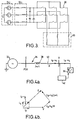
- Figure 4a shows a basic circuit diagram for an electric actuator load supplied by a controlled converter.
- the AC supply 32 is connected via a cable 34 to the input of a converter 36.
- the cable 34 is represented by a pure inductor 38 and a pure resistor 40. Although only a single cable is illustrated, it will be appreciated that the AC supply is 3-phase.
- the converter 36 is controlled so as to draw both a real current i p and a reactive current i q by varying the PWM scheme so as to introduce a phase angle between the voltage wave form at the converter and the current drawn by the converter.
- Figure 4b shows the phasor diagram for the circuit shown in Figure 4a.
- the voltages dropped across the resistor 40 and inductor 38 now have both a real and reactive element and their phases are correspondingly altered.
- the magnitude of the reactive current i q it can be seen from Figure 4b that not only is the resultant current i p + i q in phase with the AC supply at the point of regulation, i.e. the power factor at the point of regulation is substantially unity, the magnitude of the voltage V at the point of connection to the active converter 36 is substantially equal to the magnitude of the output voltage E of the AC supply.
- the voltage dropped across the reactive link 34 has been substantially reduced, thereby allowing smaller and lighter cables to be utilised for any given load.
- the reactive power compensation provided by the converter also needs to be variable. This is provided by varying the switching of the semiconductor switches 16.
- Figure 4b shows that the voltage magnitude at the load can be made substantially the same as that at the point of regulation. It could be beneficial in some applications to boost the input voltage by increasing the reactive power compensation provided by the active converter. This is particularly relevant to the matrix converter, where at present the output voltage of the converter is restricted to approximately 87% of the input voltage. The voltage "loss" with respect to the point of regulation can therefore be effectively improved.
- FIG. 5 shows a hardware schematic of an open loop control system for controlling the switching of the converter according to an embodiment of the present invention.
- An AC supply 32 is connected via a cable 34 to a converter 36.
- Measured values of the currents in each of the phases at the load end of the cable 34 are input to a current transformation block 44 within a converter controller, generally indicated as 42, that transforms the 3-phase current signals into equivalent DC signals using 3-phase to 2-phase (D&Q) mathematical transformation techniques to derive the inphase and quadrature currents.
- the phase angle and frequency of the voltage of the 3-phase signals is also measured by a phase and frequency block 46, the output of which is input to the current transformation block 44.
- the D&Q outputs relate to the real and reactive components respectively.
- the real current value i d is input to an inverting input of an adder 48.
- the output of the converter 36 is connected to a load 42, via the DC link capacitor 19.
- the DC voltage across the capacitor 19 is measured and input to an inverting input of a summation block 50, which also receives at a non-inverting input thereof a DC reference voltage (V dc order), to derive an error signal.
- This error signal is applied to a first control function, for example a proportional integral differential (PID) controller 52, to derive a real current demand i d .
- PID proportional integral differential
- the real current demand is compared with the measured real current value derived from the 3-phase to DQ transformation at the summation block 48.
- the output of the summation block 48 is therefore a real current error value and supplied to a first input of a second control function 54 to provide a real voltage value V d that is applied to a DQ to 3-phase (reverse) transformation block 56.
- the measured real current value from the 3-phase to DQ transformation block 44 is also input to an data processor 58, which also receives as an input the phase and frequency signals from the phase and frequency detection block 46.
- the data processor 58 has been given prior knowledge of the resistance and inductance of the cable 34 and uses this to perform phasor like calculations of the type shown in Figure 4b together with knowledge of the measured current value and power system frequency to calculate the required reactive current i q demand. This is compared with the measured value of reactive current supplied as a second output from the 3-phase to DQ transformation block 44 to derive an reactive current i q error signal at summation block 60. This reactive current error signal is input to a further PID controller 62 to provide a reactive voltage term V q that is also applied to the DQ to 3-phase transformation block 56.
- the output from the DQ to 3-phase transformation block provides alternating waveforms that are used by a pulsewidth modulation block to provide switching signals that are input to the active converter 36.
- the circuit shown in Figure 5 requires knowledge of the reactive and resistive properties of the cable 34 in order to establish the algorithm run by algorithm processor 58.
- the control circuit responds to alter both the real current and reactive current drawn by the active converter 36 by altering the switching angles and times of the semiconductor switches within the converter.
- FIG. 6 shows a further embodiment of the present invention in which a control system having closed loop control is provided. Where applicable, like features are given like reference numerals to Figure 5.
- the arrangement for determining the real current value is as previously described with reference to Figure 5.
- the measured real current is no longer input to a data processor implementing an open loop reactive power control algorithm.
- the AC supply voltage measured at the input to the phase and frequency block 46 is also input to a RMS detector 64, the output of which is compared with a demanded AC voltage to provide an AC error signal.
- the AC error signal is input to a further PID controller 66 to derive a reactive current demand i q that is compared with the measured reactive current at the summation block 60.
- the required reactive voltage V q is then derived in the same manner as described with respect to Figure 5.
- Figure 7 schematically illustrates voltage and current wave forms appearing at the load end of the cable having an inductance of 50 micro Henry and a resistance of 0.14 Ohms, and where the load is simulated to be 6 Ohms, the DC power supplied is 26.6 kW, the AC frequency is 400 Hz and the power factor is 0.88. Under these conditions, as shown in the portion denoted 80 of the graphs, the current and voltage are in-phase and the RMS voltage is approximately 102 volts.
- a reactive power demand is instigated by the controller and in the second portion of the graph, generally labelled 82 it can be seen that a phase shift has now occurred between the current and the voltage with the peak current increasing from 139 to approximately 176 amps, and the RMS voltage increasing from 102 to 109.6 volts. It is thus possible, by forcing the flow of an out of phase current, to reduce the apparent voltage drop seen across a cable. Thus, for a given voltage drop the cable can be thinner and lighter.
Landscapes
- Engineering & Computer Science (AREA)
- Power Engineering (AREA)
- Ac-Ac Conversion (AREA)
- Control Of Electrical Variables (AREA)
Abstract
Description
Claims (20)
- An apparatus for providing reactive power compensation, characterised by a converter (36) connected to a variable frequency AC supply (32) via a cable (34) having a reactance, and a converter controller (42) arranged to control the converter (36) so as to draw reactive current from or supply reactive current to the AC supply, whereby a power factor at the AC supply (32) and/or a voltage (E, V) at a predetermined point of the cable (34) is maintained within a predetermined range.
- An apparatus as claimed in claim 1, characterised in that the converter controller (42) is arranged to maintain the voltage (V) at a load served by the cable or at an input to the converter within a predetermined range.
- An apparatus as claimed in claim 1 or 2, characterised in that the generator is a variable frequency generator.
- An apparatus as claimed in any one of the preceding claims, characterised in that the converter controller (42) calculates the reactive current to be drawn or supplied by the converter (36) on the basis of voltage at the load or at an input to the converter and knowledge of the cable properties, and generator frequency.
- An apparatus as claimed in any one of claims 1 to 3, characterised in that the converter controller (42) causes the converter to perform closed loop control based on a difference between a measured voltage and a target voltage.
- An apparatus as claimed in any one of claims 1 to 3 characterised in that the converter controller (42) controls the converter (36) based on the difference between a measured power factor at the AC supply and a demanded power factor value.
- An apparatus as claimed in any one of the preceding claims, characterised in that the converter operates with a poly-phase AC supply.
- An apparatus as claimed in any one of the preceding claims, characterised in that the converter (36) is a rectifier, a rectifier inverter or a matrix converter.
- An apparatus as claimed in any one of the preceding claims, characterised in that the apparatus is operable to back drive the generator with current from a back driven actuator.
- An apparatus as claimed in claim 9, characterised in that the back driven current is phase shifted.
- An aircraft including an AC generator, a cable, a converter and a load, wherein the AC generator is a variable frequency generator and provides power to the load via the cable (34) and the converter (36), and wherein the cable has a reactance, and a converter controller (42) is arranged to control the converter (36) so as to draw current from or supply current to the AC supply such that a power factor at the AC supply or a voltage at the load end of the cable is maintained within a predetermined range.
- A method of providing reactive power compensation, characterised in that the method comprises providing a controllable converter (36) connected to an AC supply (32) via a cable (34) having some reactance, and controlling the converter so as to draw reactive current from or supply reactive current to the AC supply in order to control a power factor at the AC supply, a voltage (E) at the AC supply, or a voltage (V) at the converter, such that it remains within a predetermined range.
- A method as claimed in claim 12, characterised in that the AC supply (32) is a variable frequency AC generator.
- A method as claimed in claim 12 or 13 characterised in that the method further comprises determining the reactive current to be drawn or supplied by the converter based on the reactance of the cable (34) and at least one of a frequency of the AC supply (32) and a desired voltage (V) at the converter (36).
- A method as claimed in claim 12 or 13, characterised in that the method further comprises determining the reactive current to be drawn or supplied by using a closed loop control system to compare the power factor at the AC supply (32) with a desired power factor.
- A method as claimed in claim 12 or 13, characterised in that the method further comprises determining the reactive current to be drawn or supplied by using a closed loop control system to compare the voltage (V) at an input to the converter (36) with a desired voltage.
- A method as claimed in claim 16, characterised in that the comparison produces a voltage error value which is processed using a function including at least one of an integral and proportional term, to provide a signal which is indicative of a reactive current required in order to hold the voltage (V) at the converter (36) within a predetermined range.
- A method as claimed in any one of claims 12 to 17, characterised in that the AC supply (32) is a polyphase supply.
- A method as claimed in any one of claims 12 to 18 characterised in that the converter controller includes a feedback loop for holding a DC link voltage within the converter within a predetermined range.
- A converter controller for controlling a converter to draw or supply reactive current from or to a cable such that, in use, a voltage at an input to a converter controlled by the converter controller or a power factor of a generator supplying power to the converter remains within a predetermined range.
Applications Claiming Priority (2)
| Application Number | Priority Date | Filing Date | Title |
|---|---|---|---|
| GB0206368 | 2002-03-18 | ||
| GBGB0206368.3A GB0206368D0 (en) | 2002-03-18 | 2002-03-18 | Reactive power control |
Publications (2)
| Publication Number | Publication Date |
|---|---|
| EP1347552A2 true EP1347552A2 (en) | 2003-09-24 |
| EP1347552A3 EP1347552A3 (en) | 2005-04-27 |
Family
ID=9933207
Family Applications (1)
| Application Number | Title | Priority Date | Filing Date |
|---|---|---|---|
| EP03251280A Withdrawn EP1347552A3 (en) | 2002-03-18 | 2003-03-04 | Reactive power control |
Country Status (3)
| Country | Link |
|---|---|
| US (1) | US20030173938A1 (en) |
| EP (1) | EP1347552A3 (en) |
| GB (1) | GB0206368D0 (en) |
Cited By (2)
| Publication number | Priority date | Publication date | Assignee | Title |
|---|---|---|---|---|
| EP2071692A1 (en) * | 2007-12-13 | 2009-06-17 | Hamilton Sundstrand Corporation | Motor drive architecture for high frequency AC bus |
| CN102721860A (en) * | 2012-07-05 | 2012-10-10 | 南京亚派科技实业有限公司 | Reactive power detection method based on specified power factor |
Families Citing this family (6)
| Publication number | Priority date | Publication date | Assignee | Title |
|---|---|---|---|---|
| US7248946B2 (en) * | 2004-05-11 | 2007-07-24 | Advanced Energy Conversion, Llc | Inverter control methodology for distributed generation sources connected to a utility grid |
| US9365122B2 (en) * | 2011-09-20 | 2016-06-14 | GM Global Technology Operations LLC | Onboard power line conditioning system for an electric or hybrid vehicle |
| US9588557B2 (en) | 2011-11-11 | 2017-03-07 | Thomas Alexander Wilkins | Reactive following for distributed generation and loads of other reactive controller(s) |
| US10044305B2 (en) | 2016-12-22 | 2018-08-07 | Hamilton Sundstrand Corporation | Controlling aircraft VFG over voltage under fault or load-shed |
| US10541608B1 (en) * | 2018-06-29 | 2020-01-21 | Linear Technology Holding, LLC | Differential controller with regulators |
| US11664722B2 (en) * | 2019-12-05 | 2023-05-30 | Abb Power Electronics Inc. | Technologies for controlling AC-to-DC converters |
Family Cites Families (4)
| Publication number | Priority date | Publication date | Assignee | Title |
|---|---|---|---|---|
| CA2011563C (en) * | 1989-03-08 | 1994-05-10 | Kiyoshi Nakata | Power conversion system |
| US5051685A (en) * | 1990-08-22 | 1991-09-24 | Magnetek, Inc. | Waveform corrector |
| JP2760666B2 (en) * | 1991-03-15 | 1998-06-04 | 株式会社東芝 | Method and apparatus for controlling PWM converter |
| US6597179B2 (en) * | 1999-11-19 | 2003-07-22 | Gelcore, Llc | Method and device for remote monitoring of LED lamps |
-
2002
- 2002-03-18 GB GBGB0206368.3A patent/GB0206368D0/en not_active Ceased
-
2003
- 2003-03-04 EP EP03251280A patent/EP1347552A3/en not_active Withdrawn
- 2003-03-17 US US10/388,469 patent/US20030173938A1/en not_active Abandoned
Cited By (4)
| Publication number | Priority date | Publication date | Assignee | Title |
|---|---|---|---|---|
| EP2071692A1 (en) * | 2007-12-13 | 2009-06-17 | Hamilton Sundstrand Corporation | Motor drive architecture for high frequency AC bus |
| US7710058B2 (en) | 2007-12-13 | 2010-05-04 | Hamilton Sundstrand Corporation | Motor drive architecture for high frequency AC bus |
| CN102721860A (en) * | 2012-07-05 | 2012-10-10 | 南京亚派科技实业有限公司 | Reactive power detection method based on specified power factor |
| CN102721860B (en) * | 2012-07-05 | 2016-01-20 | 南京亚派科技股份有限公司 | Based on the reactive power detection method of specified power factor |
Also Published As
| Publication number | Publication date |
|---|---|
| EP1347552A3 (en) | 2005-04-27 |
| US20030173938A1 (en) | 2003-09-18 |
| GB0206368D0 (en) | 2002-05-01 |
Similar Documents
| Publication | Publication Date | Title |
|---|---|---|
| EP1953907B1 (en) | Systems and methods for improved motor drive power factor control | |
| AU2008227057B2 (en) | Motor drive using flux adjustment to control power factor | |
| US5751138A (en) | Active power conditioner for reactive and harmonic compensation having PWM and stepped-wave inverters | |
| Sul et al. | Design and performance of a high-frequency link induction motor drive operating at unity power factor | |
| EP2424102B1 (en) | Single-phase voltage type AC/DC converter, three-phase voltage type AC/DC converter, and stabilization control method | |
| US8513911B2 (en) | Power converters | |
| EP2009779A2 (en) | Cross current control for a power system with parallel converters | |
| EP2270969A1 (en) | Control methods for parallel-connected power converters | |
| KR102009512B1 (en) | Apparatus and method for generating offset voltage of 3-phase inverter | |
| US20020008982A1 (en) | Method and control system for voltage control at a converter station | |
| GB2449119A (en) | AC-AC converter | |
| US7057908B2 (en) | Method and arrangement in connection with network inverter | |
| WO2010116840A1 (en) | Induction motor control device and induction motor group control system | |
| Li et al. | Power-factor compensation for PWM CSR–CSI-fed high-power drive system using flux adjustment | |
| EP1347552A2 (en) | Reactive power control | |
| WO2017008245A1 (en) | Transformer-less static synchronous series compensator and method therefor | |
| US12244238B2 (en) | Power conversion system | |
| Qiu et al. | High performance current source inverter fed induction motor drive with minimal harmonic distortion | |
| Zargari et al. | A three-phase current-source type PWM rectifier with feed-forward compensation of input displacement factor | |
| CN102570867B (en) | There is the electric power converter of controlled current source | |
| Bouafia et al. | Regular paper A Fuzzy-Logic-Based Controller for Three-Phase PWM Rectifier With Unity Power Factor Operation | |
| Rajesh et al. | A shunt active power filter for 12 pulse converter using source current detection approach | |
| Masoud | Fully controlled 5-phase, 10-pulse, line commutated rectifier | |
| Taha | Power electronics application for more electric aircraft | |
| KR20230142736A (en) | DC power supplies and railway substations containing them |
Legal Events
| Date | Code | Title | Description |
|---|---|---|---|
| PUAI | Public reference made under article 153(3) epc to a published international application that has entered the european phase |
Free format text: ORIGINAL CODE: 0009012 |
|
| AK | Designated contracting states |
Kind code of ref document: A2 Designated state(s): AT BE BG CH CY CZ DE DK EE ES FI FR GB GR HU IE IT LI LU MC NL PT RO SE SI SK TR |
|
| AX | Request for extension of the european patent |
Extension state: AL LT LV MK |
|
| PUAL | Search report despatched |
Free format text: ORIGINAL CODE: 0009013 |
|
| AK | Designated contracting states |
Kind code of ref document: A3 Designated state(s): AT BE BG CH CY CZ DE DK EE ES FI FR GB GR HU IE IT LI LU MC NL PT RO SE SI SK TR |
|
| AX | Request for extension of the european patent |
Extension state: AL LT LV MK |
|
| 17P | Request for examination filed |
Effective date: 20051017 |
|
| AKX | Designation fees paid |
Designated state(s): DE ES FR GB IT |
|
| RAP1 | Party data changed (applicant data changed or rights of an application transferred) |
Owner name: GOODRICH CONTROL SYSTEMS LTD |
|
| RAP1 | Party data changed (applicant data changed or rights of an application transferred) |
Owner name: GOODRICH CONTROL SYSTEMS |
|
| 17Q | First examination report despatched |
Effective date: 20090713 |
|
| STAA | Information on the status of an ep patent application or granted ep patent |
Free format text: STATUS: THE APPLICATION IS DEEMED TO BE WITHDRAWN |
|
| 18D | Application deemed to be withdrawn |
Effective date: 20100126 |