TECHNICAL FIELD
This invention relates to an electronic device
suitable for being applied to remote control devices, portable
telephones, radio receiver units, and the like.
BACKGROUND ART
There have been proposed remote control devices for
television receivers in which the key buttons have been
designed to be luminescent, in order that the positions of the
key buttons for operation can be judged even in darkness.
While a luminescent design for these key buttons has
enabled the user to judge the positions of the key buttons, it
has not been possible for the user to judge the functions of
the key buttons.
DISCLOSURE OF THE INVENTION
In light of this, an object of the present invention
is to enable the user to judge the positions and functions of
key buttons for operation, even in darkness.
In electronic equipment including a plurality of
operation elements, an electronic device of this invention
comprises: operation means, in which the plurality of
operation elements are integrally formed with a base member
which emits light through the release of stored optical
energy; switching means, which puts a circuit of the
electronic equipment into a closed state or an open state
accompanied by depression of an operation element; and cover
means, comprising holes corresponding to each of the operation
elements for the purpose of depressing the operation elements,
and which transmits at least part of the light emitted by the
operation means.
According to this invention, since a plurality of
operation elements and a base member which emits light through
the release of stored optical energy are formed integrally,
the entirety of this operation means emits light, the emitted
light is transmitted through the transmissive cover means, and
the transmission of light being through this cover means,
thereby enables the user to judge the positions and functions
of the operation elements for operation, even in darkness.
BRIEF DESCRIPTION OF DRAWINGS
Fig. 1 is an exploded perspective view showing an
embodiment of a remote control device according to the
invention;
Fig. 2 is a top view of the embodiment in Fig. 1;
Fig. 3A is a partly enlarged perspective view
showing an example of the rear face of an operation structure;
Fig. 3B is a partly enlarged top view showing an
example of a connection contact;
Fig. 4 is a diagram used in explaining this
invention;
Fig. 5 is a partly enlarged perspective view, used
in explaining this invention; and,
Fig. 6 is a perspective view showing another
embodiment of this invention.
BEST MODE FOR CARRYING OUT THE INVENTION
Referring to the drawings, hereinafter, embodiments
of the electronic device according to the present invention
will be explained.
Figs. 1 through 5 are diagrams showing an embodiment
in which this invention is applied to a remote control device
of a television receiver or the like. Fig. 2 is a top plan
view seen from above the remote control device of this
embodiment; as shown in Fig. 1, the remote control device of
this embodiment comprises an upper panel 1, a semitransparent
sheet 2, an operation structure 3 comprising a plurality of
key buttons 3a, 3a, ... and a base member 3b, a switching
button 4, a circuit board 5, and a lower case 6.
As shown in Figs. 1 and 2, this lower case 6 is a
rectangular container formed of a synthetic resin, into which
the rectangular semitransparent sheet 2, operation structure 3,
and circuit substrate 5 are inserted. The upper panel 1 serves
as a lid for the lower case 6 of a rectangular box, and is
formed from, for example, transparent acrylic which transmits
light; a plurality of holes 1a, 1a, ... are formed in the
upper panel 1, and through which the plurality of key buttons
3a, 3a, ... are penetrated, so that the user can operate the
plurality of key buttons 3a, 3a.
On a rectangular printed circuit board of this
circuit board 5, circuit elements for remotely controlling a
television receiver and DVD player, for example, and a
plurality of connection contacts 5a, 5a, ..., each short-circuited
to the plurality of key buttons 3a, 3a, ..., are
mounted and further an infrared light-emitting diode 5b,
photoelectric conversion element 5c for supplying power, and
the like, are provided at predetermined positions. The
switching button 4, which switches functions between that of a
remote control device for a television receiver and that of a
remote control device for a DVD player, is provided at a
predetermined position.
The operation structure 3 comprises the plurality of
key buttons 3a, 3a, ... for inputting operations of a
television receiver or DVD player by the user, and the
connecting base member 3b formed integrally with this
plurality of key buttons 3a, 3a, ..., using silicon rubber,
for example, in a manner similar to the prior art.
In this embodiment, the silicon rubber or other
material forming this operation structure 3 is made to contain
a luminescent material, such as, for example, "Picariko"
(manufactured by Chemitech Inc.). In this case, the light
emission color differs depending on the type of "Picariko"
luminescent material; for example, the color is green for
"Picariko CP-05", blue for "Picariko CP-10", purple for
"Picariko CP-20", and yellow for "Picariko CP-30". It is
possible, for example, to use luminescent materials with
different light emission colors in the principal key buttons
3a, 3a, ... of the operation structure 3.
In this case, the key buttons 3a, 3a, ... are formed
in such a manner as to each protrude a predetermined height
from the base member 3b on the front side of the operation
structure 3, as shown in Fig. 1. As shown in Fig. 3A, carbon-impregnated
portions 7, which are corresponding to the key
buttons 3a, 3a, ..., are provided on the rear side of the base
member 3b, and by means of these carbon-impregnated portions 7,
the connection contacts 5a, 5a, ... on the circuit board 5
shown in Fig. 3B can be connected to be short-circuited as the
key buttons 3a, 3a, ..., are pressed downward.
The semitransparent sheet 2 formed with, for example,
polycarbonate sheet which transmits light emitted from the
base member 3b, is positioned between the base member 3b of
the operation structure 3 and the upper panel 1, and is
provided with holes 2a, 2a, ... through which the plurality of
key buttons 3a, 3a ... penetrate. Further, in proximity to
these holes 2a, 2a, ..., displays 2b, for example, indication
of the function related to the key buttons 3a, 3a, ... which
penetrate each hole 2a, 2a ... are printed or otherwise
displayed.
As shown in Figs. 1 and 2, the remote control device
according to this embodiment is configured such that the
circuit board 5 is positioned within the lower case 6,
together with the operation structure 3 in a predetermined
position with respect to this circuit board 5, with the
semitransparent sheet 2 above the operation structure 3 in a
way that the key buttons 3a, 3a, ... penetrate the holes 2a,
2a, ..., with the upper panel 1 fixed in place with the key
buttons 3a, 3a, ... penetrating the holes 1a, 1a, ..., acting
as a lid for the lower case 6, and with the switching button 4
installed in a predetermined position.
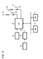
As shown in Fig. 4, in this remote control device,
control signals are supplied to a microcomputer 10 according
to the operation of the key buttons 3a, 3a, ... by the user;
in this microcomputer 10, remote control codes are read from a
ROM 11 in which remote control codes corresponding to these
control signals are stored in advance, the infrared light-emitting
diode 5b is caused to emit light according to these
remote control codes, and a television receiver, DVD player,
or similar is operated remotely.
In Fig. 4, a working RAM 12 is connected to the
microcomputer 10 via a bus line, while a predetermined program
or similar is stored in the ROM 11, which is connected to the
microcomputer 10 via the bus line. In Fig. 4, Numeral 13
denotes power supply terminals.
In this embodiment, as described above, the
operation structure 3, in which a plurality of key buttons 3a,
3a, ... and a rectangular base member 3b connecting this
plurality of key buttons 3a, 3a, ... are formed integrally,
contains a luminescent material; hence the entirety of the
operation structure 3 emits light, and this emitted light is
transmitted through the semitransparent sheet 2 and upper
panel 1, as well as the plurality of key buttons 3a, 3a, ...
emitting light. Therefore, even in darkness, the positions of
the plurality of key buttons 3a, 3a, ..., and the displays
related to the key buttons 3a, 3a, ..., that is, their
functions, can be judged.
In this embodiment, displays, for example, printed
functions or similar related to the key buttons 3a, 3a, ...,
are provided on the semitransparent sheet 2; hence the related
displays are provided without difficulty, and in addition,
when the remote control device is marketed in various
countries around the world, it is only necessary to replace
the semitransparent sheet 2 with another sheet having displays
in the language of the country of use. Also, since the related
displays are provided on the semitransparent sheet 2, the
displays are not touched during use of the remote control
device, so that the printing or similar is not peeled or
otherwise removed by rubbing or similar.
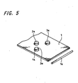
In this embodiment, in order to increase the light
stored in the operation structure 3, a light-emitting diode 14
is provided in one side of the upper panel 1 as shown in Figs.
4 and 5; whether the user is holding the remote control device
is detected by means of a sensor 15, such as, for example, an
electrostatic capacitance sensor, infrared sensor, or
mechanical switch, and the light-emitting diode 14 is then
caused to emit light for a predetermined length of time. When
the light-emitting diode 14 emits light, light is stored in
the luminescent material of the base member 3b and key buttons
3a, 3a, ... of the operation structure 3.
Specifically, as shown in Fig. 4, the output signal
of this sensor 15 is supplied to a detection circuit 16, and
when this detection circuit 16 detects that the remote control
device is being held by the user, the detected signal is
supplied to the microcomputer 10, and the microcomputer 10
causes the light-emitting diode 14 to emit light for a
predetermined length of time.
In the above-described embodiment, the case where
this invention is applied to a remote control device is
described; however as shown in Fig. 6, it is also possible to
apply this invention to a radio receiver, portable telephone,
or other electronic devices. In Fig. 6, a front panel 20
composed of an light transmission material, and an operation
structure, in which a plurality of key buttons 21a, 21a, ...
as well as a base member connecting the plurality of key
buttons 21a, 21a, ... are formed integrally, contain
luminescent material. Otherwise the configuration is similar
to that of Fig. 1.
In the embodiment according to Fig. 6, it is
understandable that an advantageous result similar to that of
the embodiment shown in Figs. 1 and 2 is also obtained.
In the above-described embodiments, the displays
related to the key buttons 3a, 3a, ... are provided on the
semitransparent sheet 2; however, the displays related to the
key buttons 3a, 3a, ... (21a, 21a, ...) may be provided on the
upper (front) panel 1 (20), on the side near the base member,
without providing the semitransparent sheet 2. Such a
configuration can also prevent the disappearance of the
displays related to the key buttons 3a, 3a, ... (21a,
21a, ...) due to rubbing or similar. Also, in this case the
upper panel may be semitransparent rather than transparent,
whereby a burr or the like originated in forming of the base
member 3b is not easily seen, and fluctuation in brightness at
different locations on the base member 3b are absorbed, so
that light is transmitted in such a way that light emission is
averaged.
The present invention is not limited to the above-described
embodiments, and of course various other
configurations may be adopted without deviating from the gist
of this invention.