EP1347291A1 - Flaw detector - Google Patents
Flaw detector Download PDFInfo
- Publication number
- EP1347291A1 EP1347291A1 EP01272862A EP01272862A EP1347291A1 EP 1347291 A1 EP1347291 A1 EP 1347291A1 EP 01272862 A EP01272862 A EP 01272862A EP 01272862 A EP01272862 A EP 01272862A EP 1347291 A1 EP1347291 A1 EP 1347291A1
- Authority
- EP
- European Patent Office
- Prior art keywords
- packaging material
- variable
- flaw detection
- flaw
- packaging
- Prior art date
- Legal status (The legal status is an assumption and is not a legal conclusion. Google has not performed a legal analysis and makes no representation as to the accuracy of the status listed.)
- Granted
Links
Images


Classifications
-
- G—PHYSICS
- G01—MEASURING; TESTING
- G01N—INVESTIGATING OR ANALYSING MATERIALS BY DETERMINING THEIR CHEMICAL OR PHYSICAL PROPERTIES
- G01N27/00—Investigating or analysing materials by the use of electric, electrochemical, or magnetic means
- G01N27/02—Investigating or analysing materials by the use of electric, electrochemical, or magnetic means by investigating impedance
- G01N27/04—Investigating or analysing materials by the use of electric, electrochemical, or magnetic means by investigating impedance by investigating resistance
- G01N27/20—Investigating the presence of flaws
-
- G—PHYSICS
- G01—MEASURING; TESTING
- G01M—TESTING STATIC OR DYNAMIC BALANCE OF MACHINES OR STRUCTURES; TESTING OF STRUCTURES OR APPARATUS, NOT OTHERWISE PROVIDED FOR
- G01M3/00—Investigating fluid-tightness of structures
- G01M3/40—Investigating fluid-tightness of structures by using electric means, e.g. by observing electric discharges
-
- G—PHYSICS
- G01—MEASURING; TESTING
- G01N—INVESTIGATING OR ANALYSING MATERIALS BY DETERMINING THEIR CHEMICAL OR PHYSICAL PROPERTIES
- G01N27/00—Investigating or analysing materials by the use of electric, electrochemical, or magnetic means
- G01N27/02—Investigating or analysing materials by the use of electric, electrochemical, or magnetic means by investigating impedance
- G01N27/04—Investigating or analysing materials by the use of electric, electrochemical, or magnetic means by investigating impedance by investigating resistance
- G01N27/20—Investigating the presence of flaws
- G01N27/205—Investigating the presence of flaws in insulating materials
-
- G—PHYSICS
- G01—MEASURING; TESTING
- G01N—INVESTIGATING OR ANALYSING MATERIALS BY DETERMINING THEIR CHEMICAL OR PHYSICAL PROPERTIES
- G01N33/00—Investigating or analysing materials by specific methods not covered by groups G01N1/00 - G01N31/00
- G01N33/0078—Testing material properties on manufactured objects
- G01N33/0081—Containers; Packages; Bottles
Definitions
- the present invention relates to a flaw detection apparatus.
- packaging containers formed from a packing material having a paper substrate.
- packaging containers include polyhedral packaging containers and brick-shaped packaging containers each having a flat top wall.
- packaging containers having a capacity which enables a purchaser to drink liquid food in a single serving are formed through a process of longitudinally sealing a web-shaped packaging material into a tuber shape, transversely sealing and cutting the tube-shaped packaging material at predetermined intervals to thereby form initial-shape containers, and processing the initial-shape containers to complete the packaging containers.
- a discharge opening is formed in the top wall of each packaging container and is covered with a pull tab from the outer side and with an inner seal from the inner side, and the pull tab and the inner seal are welded.
- a flaw detection apparatus which samples packaging containers at proper intervals; forms an opening in the top wall of each sampled packaging container; charges water into the packaging container; and immerses a portion of the water-charged packaging container into water stored in a vessel. Since an end surface of the aluminum foil layer is exposed to the outside of the packaging container, when electrodes are dipped in the water within the packaging container and the water within the vessel, respectively, electrical continuity is established between the two electrodes if a pinhole has been generated in the inner circumference of the packaging container to a depth reaching the aluminum foil layer.
- the conventional flaw detection apparatus requires the labor of charging water into each packaging container and partially immersing the packaging container in water stored in the vessel, the labor for flaw detection is cumbersome. Further, the flaw detection apparatus cannot inspect all packaging containers. In addition, since the flaw detection apparatus forms an opening in the top wall of packaging containers to be inspected, the inspected packaging containers are destroyed.
- An object of the present invention is to solve the problems involved in the above described convention flaw detection apparatus and to provide a flaw detection apparatus which can simplify labor necessary for flaw detection, which can inspect all packaging containers, and which does not destroy packaging container during inspection.
- a flaw detection apparatus comprises an electrode disposed in a region surrounded by a packaging material including a layer of an electrically-conductive material; a cutting member made of an electrically-conductive material and adapted to cut a predetermined portion of the packaging material; variable detection means, disposed between the electrode and the cutting member, for detecting an electrical variable; and flaw detection processing means for reading the variable and for detecting, on the basis of the variable, a flaw generated in the packaging material.
- Another flaw detection apparatus of the present invention further comprises a seal apparatus for sealing the packaging material; and the predetermined portion of the packaging material is a seal portion formed by the seal apparatus.
- the flaw detection processing means reads the variable at a timing when the cutting member cuts the seal portion.
- liquid food is charged into the region, and the electrode is dipped in the liquid food.
- FIG. 1 is a conceptual view of a flaw detection apparatus according to an embodiment of the present invention
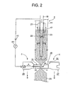
- FIG. 2 is a conceptual view used for explaining a main portion of a charging machine according to the embodiment of the present invention
- FIG. 3 is a control block diagram of the flaw detection apparatus according to the embodiment of the present invention.
- FIG. 1 is a conceptual view of a flaw detection apparatus according to an embodiment of the present invention
- FIG. 2 is a conceptual view used for explaining a main portion of a charging machine according to the embodiment of the present invention
- FIG. 3 is a control block diagram of the flaw detection apparatus according to the embodiment of the present invention.
- reference numeral 11 denotes a packaging material formed from a flexible material; e.g., a laminate that includes a first resin layer 12 made of polyethylene resin or a like resin, an aluminum foil layer 13 made of an electrically conductive material and serving as a conductive-material layer, a paper substrate 14, and a second resin layer 15 made of polyethylene resin or a like resin, which are arranged in this order from the inner side.
- the packaging material 11 assumes a web-like shape.
- the packaging material 11 is sealed longitudinally, while being transported, so as to form an unillustrated longitudinal seal portion, whereby the packaging material 11 becomes a tubular packaging material; i.e., a tube T.
- the tube T is continuously transported downward by means of an unillustrated transfer apparatus and is nipped by two seal-cut units 16 (only one seal-cut unit 16 is shown in FIG. 2) at predetermined intervals, whereby the tube T is sealed transversely and a belt-shaped lateral seal portion S is formed.
- Each of the seal-cut units 16 includes a cutting jaw 26 and a pressure jaw 27.
- a cutting bar 31 is disposed at the front end (the right-hand end in FIG. 2) of the cutting jaw 26.
- An inductor 32 serving as seal means and a seal apparatus is disposed at the front end (the left-hand end in FIG. 2) of the pressure jaw 27.
- the tube T is nipped from both sides, so that opposed portions of the packaging material 11 are pressed against each other, and opposed portions of the first resin layer 12 are welded. Thus, the tube T is sealed transversely.
- a liquid food 17 is charged into the region surrounded by the packaging material 11; i.e., within the tube T, from thereabove.
- the charge pipe 18 extends downward and has an opened lower end.
- the liquid food 17 is supplied from an unillustrated liquid food supply source to the charge pipe 18, so that the liquid food 17 is discharged from the lower end of the charge pipe 18 into the tube T along the directions of arrows shown in Fig. 2.
- the lower end of the charge pipe 18 is dipped in the liquid food 17 and is in electrical contact with the liquid food 17.
- the charge pipe 18 is formed of a metal in the present embodiment, the charge pipe 18 may be formed of an electrically conductive resin, which is an electrically conductive material.
- a float 21 In order to maintain the liquid food 17 at a constant level within the tube T, there are provided a float 21; an open/close valve 22 disposed within the charge pipe 18 in such a manner that the open/close valve 22 can assume an open position and a closed position; and a link 23 which connects the float 21 and the open/close valve 22.
- the float 21 moves upward, and the open/close valve 22 is closed by means of the link 23 so as to stop charging of the liquid food 17.
- the float 21 moves downward, and the open/close valve 22 is opened by means of the link 23 so as to charge the liquid food 17.
- the lateral seal portion S is cut in order to obtain an initial-shape container 25 containing a predetermined amount of the liquid food 17.
- a horizontally extending flat cutter 33 which serves as a cutting member, is disposed at the center of the cutting bar 31 in such a manner that the cutter 33 can advance and retract (along a direction of an arrow A).
- the cutter 33 cuts the tube T at a predetermined portion (in the present embodiment, at the center of the lateral seal portion S) of the packaging material 11.
- an air cylinder 39 serving as an actuator, is disposed at the rear end (the left-hand end in FIG. 3) of the cutter 33, and an operation medium such as compressed air is supplied from a compressed air source 38 via a changeover valve 40.
- the changeover valve 40 assumes position A or B in accordance with a changeover signal from a control section 45. At position A, the changeover valve 40 supplies compressed air from the compressed air source 38 to a chamber 39a of the air cylinder 39, and discharges compressed air from a chamber 39b of the air cylinder 39. At position B, the changeover valve 40 supplies compressed air from the compressed air source 38 to the chamber 39b of the air cylinder 39, and discharges compressed air from the chamber 39a of the air cylinder 39.
- a groove 34 is formed in the inductor 32 so as to accommodate a tip end of the cutter 33 when the cutter 33 is advanced.
- the seal-cut unit 16 is located at a seal-cut start position, at which the cutting jaw 26 and the pressure jaw 27 are advanced. Subsequently, the seal-cut unit 16 is moved downward (in the direction of arrow B) while nipping the tube T, while the cutting bar 31 and the inductor 32 are strongly pressed against the tube T, and the inductor 32 heats the aluminum foil layer 13 by means of induction heating. As a result, the opposed portions of the first resin layer 12 are welded to thereby seal the tube T transversely.
- the tube T is sealed by use of the inductor 32 through induction heating, the tube T may be sealed by use of a resistor which generates Joule heat.
- the seal-cut unit 16 is moved further downward (in the direction of arrow B), while unillustrated cutting processing means of the control section 45 causes the changeover valve 40 to assume position A in order to advance the cutter 33 to thereby cut the lateral seal portion S at the center thereof.
- a rectangular initial-shape container 25 is separated from the tube T.
- the seal-cut unit 16 then reaches a seal-cut end position.
- the cutting processing means causes the changeover valve 40 to assume position B in order to retract the cutter 33 and simultaneously retract the cutting jaw 26 and the pressure jaw 27 (move the cutting jaw 26 leftward in FIG. 2 and the pressure jaw 27 rightward in FIG. 2).
- the seal-cut unit 16 is moved upward and then moved along the direction of arrow C to the seal-cut start position.
- the initial-shape container 25, which has been formed in the above-described manner, is transported to an unillustrated forming machine, and is formed into a predetermined shape by the forming machine, whereby a packaging container is obtained.
- the cutter 33 is formed of an electrically conductive material such as a metal; and the charge pipe 18 and the cutter 33 are in electrical contact via a power source 41 and a current sensor 43, which serves as variable detection means, in order to detect any flaw formed in the packaging material 11.
- the electrically conductive material may be an electrically conductive resin.
- unillustrated flaw detection processing means of the control section 45 reads the sensor output fed from the current sensor 43, and detects any flaw generated in the packaging material 11 on the basis of the sensor output.
- the current sensor 43 is used as variable detection means in order to detect current serving as an electrical variable.
- a voltage sensor may be used as variable detection means in order to detect voltage as an electrical variable.
- the aluminum foil layer 13 is formed within the packaging material 11 and electrical continuity between the liquid food 17 and the aluminum foil layer 13 at a portion where a flaw has been generated is detected.
- a layer of an electrically conductive material such as a metal (e.g., steel) or an electrically conductive resin may be formed within the packaging material 11, in which case electrical continuity between the liquid food 17 and the electrically conductive material layer at a portion where a flaw has been generated is detected.
- the charge pipe 18 serves as an electrode.
- an electrode provided in the tube T separately from the charge pipe 18 may be dipped in the liquid food 17, in which case electrical continuity between the electrode and the cutter 33 via the power source 41 and the current sensor 43 is established in order to detect a flaw formed in the packaging material 11.
- sealing and cutting are performed simultaneously by the inductor 32 and the cutter 33, respectively.
- cutting may be performed after completion of sealing.
- the present invention can be applied to a packaging container manufacturing apparatus for manufacturing packaging containers.
Landscapes
- Chemical & Material Sciences (AREA)
- General Physics & Mathematics (AREA)
- Physics & Mathematics (AREA)
- Life Sciences & Earth Sciences (AREA)
- Health & Medical Sciences (AREA)
- General Health & Medical Sciences (AREA)
- Analytical Chemistry (AREA)
- Biochemistry (AREA)
- Immunology (AREA)
- Pathology (AREA)
- Electrochemistry (AREA)
- Chemical Kinetics & Catalysis (AREA)
- Engineering & Computer Science (AREA)
- Food Science & Technology (AREA)
- Medicinal Chemistry (AREA)
- Containers And Plastic Fillers For Packaging (AREA)
- Investigating Or Analyzing Materials By The Use Of Electric Means (AREA)
Abstract
Description
Claims (4)
- A flaw detection apparatus characterized by comprises:(a) an electrode disposed in a region surrounded by a packaging material including a layer of an electrically-conductive material;(b) a cutting member made of an electrically-conductive material and adapted to cut a predetermined portion of the packaging material;(c) variable detection means, disposed between the electrode and the cutting member, for detecting an electrical variable; and(d) flaw detection processing means for reading the variable and for detecting, on the basis of the variable, a flaw generated in the packaging material.
- A flaw detection apparatus according to claim 1, wherein(a) the flaw detection apparatus further comprises a seal apparatus for sealing the packaging material; and(b) the predetermined portion of the packaging material is a seal portion formed by the seal apparatus.
- A flaw detection apparatus according to claim 1, wherein the flaw detection processing means reads the variable at a timing when the cutting member cuts a seal portion.
- A flaw detection apparatus according to claim 1, wherein liquid food is charged into the region, and the electrode is dipped in the liquid food.
Applications Claiming Priority (3)
| Application Number | Priority Date | Filing Date | Title |
|---|---|---|---|
| JP2000399148A JP2002202277A (en) | 2000-12-27 | 2000-12-27 | Damage detection device |
| JP2000399148 | 2000-12-27 | ||
| PCT/JP2001/011432 WO2002054053A1 (en) | 2000-12-27 | 2001-12-26 | Flaw detector |
Publications (3)
| Publication Number | Publication Date |
|---|---|
| EP1347291A1 true EP1347291A1 (en) | 2003-09-24 |
| EP1347291A4 EP1347291A4 (en) | 2008-03-05 |
| EP1347291B1 EP1347291B1 (en) | 2008-10-15 |
Family
ID=18863983
Family Applications (1)
| Application Number | Title | Priority Date | Filing Date |
|---|---|---|---|
| EP01272862A Expired - Lifetime EP1347291B1 (en) | 2000-12-27 | 2001-12-26 | Flaw detector |
Country Status (9)
| Country | Link |
|---|---|
| US (1) | US7015700B2 (en) |
| EP (1) | EP1347291B1 (en) |
| JP (1) | JP2002202277A (en) |
| KR (1) | KR100535433B1 (en) |
| CN (1) | CN1210564C (en) |
| AU (1) | AU2002219537B2 (en) |
| DE (1) | DE60136219D1 (en) |
| TW (1) | TW508333B (en) |
| WO (1) | WO2002054053A1 (en) |
Cited By (1)
| Publication number | Priority date | Publication date | Assignee | Title |
|---|---|---|---|---|
| EP1965207A4 (en) * | 2005-12-20 | 2010-09-15 | Tetra Laval Holdings & Finance | APPARATUS AND METHOD FOR SEALING CONTROL |
Families Citing this family (7)
| Publication number | Priority date | Publication date | Assignee | Title |
|---|---|---|---|---|
| JP4004918B2 (en) * | 2002-10-22 | 2007-11-07 | 日本テトラパック株式会社 | Sample preparation device |
| KR101264258B1 (en) | 2005-12-21 | 2013-05-22 | 재단법인 포항산업과학연구원 | Leakage Detector in Channel Induction Furnace |
| CN101363811B (en) * | 2007-08-08 | 2011-11-30 | 骆立波 | Automatic detection and recording device for completeness integrity of coated film |
| ES2397233T3 (en) * | 2008-06-09 | 2013-03-05 | Tetra Laval Holdings & Finance Sa | Packaging and filling machine |
| BR112013015409A2 (en) * | 2010-12-29 | 2016-09-20 | Tetra Laval Holdings & Finance | method and device for defect detection in a packaging laminate |
| CN105352420B (en) * | 2015-11-09 | 2017-11-14 | 武汉大学 | A kind of TBM hob abrasion on-line real time monitoring device and monitoring method |
| JP7296512B1 (en) | 2022-10-20 | 2023-06-22 | 株式会社クボタケミックス | Drainage collecting pipe inspection method |
Family Cites Families (12)
| Publication number | Priority date | Publication date | Assignee | Title |
|---|---|---|---|---|
| DE2553854A1 (en) * | 1975-11-29 | 1977-06-02 | Bosch Gmbh Robert | METHOD AND APPARATUS FOR MANUFACTURING LIQUID-FILLED PACKAGES |
| DE2715399A1 (en) * | 1976-07-15 | 1978-01-19 | Takeda Chemical Industries Ltd | METHOD AND DEVICE FOR CHECKING CLOSED CONTAINERS FOR DEFECTS |
| DE2636799C3 (en) * | 1976-08-16 | 1979-01-25 | Hoechst Ag, 6000 Frankfurt | Plastic container and method for non-destructive testing of the tightness of the closed plastic container |
| JPS5476284A (en) * | 1977-11-30 | 1979-06-18 | Otsuka Pharma Co Ltd | Method of checking whether or not there is pinhole in enclosed package |
| US4291600A (en) * | 1978-02-07 | 1981-09-29 | Kobe Steel, Limited | Process and apparatus for cutting circumferential surface to remove rod surface flaws |
| DE3621871A1 (en) * | 1985-07-01 | 1987-03-12 | Konsum Rat Ind Veb | Method for determining the optimum degree of mincing of meat substances, and sausage meat scraper for mincers, and cutter for implementing the method |
| JPH02140652A (en) * | 1988-11-21 | 1990-05-30 | Mitsubishi Kasei Corp | How to detect pinholes |
| JP3643400B2 (en) * | 1995-03-02 | 2005-04-27 | 株式会社中埜酢店 | Pinhole defect inspection method and apparatus for food packaging sheet and food sealed container |
| JP2681764B2 (en) * | 1995-07-12 | 1997-11-26 | ジョーベン電機株式会社 | Inspection method of sealed package |
| SE504858C2 (en) * | 1995-08-18 | 1997-05-12 | Tetra Laval Holdings & Finance | Methods for quality control and prepared packaging containers and material for this |
| JPH1125774A (en) * | 1997-07-02 | 1999-01-29 | Mitsubishi Cable Ind Ltd | Testing method for breaking of cable |
| EP1057619B1 (en) * | 1999-05-14 | 2004-04-07 | Tetra Laval Holdings & Finance SA | Flaw detector for package closures |
-
2000
- 2000-12-27 JP JP2000399148A patent/JP2002202277A/en active Pending
-
2001
- 2001-12-25 TW TW090132257A patent/TW508333B/en not_active IP Right Cessation
- 2001-12-26 KR KR10-2003-7008632A patent/KR100535433B1/en not_active Expired - Fee Related
- 2001-12-26 WO PCT/JP2001/011432 patent/WO2002054053A1/en not_active Ceased
- 2001-12-26 AU AU2002219537A patent/AU2002219537B2/en not_active Ceased
- 2001-12-26 US US10/432,908 patent/US7015700B2/en not_active Expired - Fee Related
- 2001-12-26 DE DE60136219T patent/DE60136219D1/en not_active Expired - Fee Related
- 2001-12-26 EP EP01272862A patent/EP1347291B1/en not_active Expired - Lifetime
- 2001-12-26 CN CNB018214827A patent/CN1210564C/en not_active Expired - Fee Related
Cited By (3)
| Publication number | Priority date | Publication date | Assignee | Title |
|---|---|---|---|---|
| EP1965207A4 (en) * | 2005-12-20 | 2010-09-15 | Tetra Laval Holdings & Finance | APPARATUS AND METHOD FOR SEALING CONTROL |
| CN101341400B (en) * | 2005-12-20 | 2012-01-11 | 利乐拉瓦尔集团及财务有限公司 | Sealing status inspecting apparatus and sealing status inspecting method |
| US8104363B2 (en) | 2005-12-20 | 2012-01-31 | Tetra Laval Holdings & Finance S.A. | Sealing status inspecting apparatus and sealing status inspecting method |
Also Published As
| Publication number | Publication date |
|---|---|
| DE60136219D1 (en) | 2008-11-27 |
| CN1210564C (en) | 2005-07-13 |
| TW508333B (en) | 2002-11-01 |
| CN1483143A (en) | 2004-03-17 |
| EP1347291A4 (en) | 2008-03-05 |
| KR20030072580A (en) | 2003-09-15 |
| US20040027133A1 (en) | 2004-02-12 |
| WO2002054053A1 (en) | 2002-07-11 |
| AU2002219537B2 (en) | 2005-03-03 |
| JP2002202277A (en) | 2002-07-19 |
| EP1347291B1 (en) | 2008-10-15 |
| KR100535433B1 (en) | 2005-12-09 |
| US7015700B2 (en) | 2006-03-21 |
Similar Documents
| Publication | Publication Date | Title |
|---|---|---|
| EP1460406A1 (en) | Sealed condition inspecting device | |
| US3632943A (en) | Apparatus for making seals on tubular containers | |
| JP5550134B2 (en) | Inspection method for defective sealing of containers using infrared rays | |
| EP1347291B1 (en) | Flaw detector | |
| US3855531A (en) | Method of testing the seals of food containers and containers suitable therefor | |
| JP2016513250A5 (en) | ||
| EP1555524B1 (en) | Vessel inspection method and vessel inspection device | |
| JP2007170893A (en) | Seal state inspection device and seal state inspection method | |
| US5147491A (en) | Form, fill and seal process and device | |
| KR20040069203A (en) | Sealed condition inspection device | |
| JP2000352544A (en) | Control unit for checking the integrity of the tear-off closure mounted in the opening of the packaging strip | |
| SE504858C2 (en) | Methods for quality control and prepared packaging containers and material for this | |
| JP5492504B2 (en) | Sealed package inspection equipment | |
| JP2006084362A (en) | Seal condition inspection device | |
| JP2004268932A (en) | Seal device and seal management method | |
| JP2014184981A (en) | Filling and packaging machine with welding determination means of stopper | |
| JP5105505B2 (en) | Container inspection method and container inspection apparatus | |
| JP4795090B2 (en) | Packaging inspection equipment | |
| JP4444624B2 (en) | Packaging inspection equipment | |
| JP2008150104A (en) | Container inspection method and container inspection apparatus | |
| JP2007170895A (en) | Seal state inspection device and seal state inspection method | |
| JP2009085803A (en) | Quality inspection method | |
| JP2014104984A (en) | Molding inspection device, molding inspection method, package filling device, and package filling method | |
| JPH11351945A (en) | Level detecting method and liquid level detecting device | |
| JP2001174442A5 (en) |
Legal Events
| Date | Code | Title | Description |
|---|---|---|---|
| PUAI | Public reference made under article 153(3) epc to a published international application that has entered the european phase |
Free format text: ORIGINAL CODE: 0009012 |
|
| 17P | Request for examination filed |
Effective date: 20030603 |
|
| AK | Designated contracting states |
Kind code of ref document: A1 Designated state(s): AT BE CH CY DE DK ES FI FR GB GR IE IT LI LU MC NL PT SE TR |
|
| AX | Request for extension of the european patent |
Extension state: AL LT LV MK RO SI |
|
| RBV | Designated contracting states (corrected) |
Designated state(s): DE FR GB IT |
|
| A4 | Supplementary search report drawn up and despatched |
Effective date: 20080131 |
|
| RIC1 | Information provided on ipc code assigned before grant |
Ipc: G01M 3/40 20060101ALI20080125BHEP Ipc: B65B 57/00 20060101ALI20080125BHEP Ipc: G01N 27/20 20060101AFI20020712BHEP |
|
| GRAP | Despatch of communication of intention to grant a patent |
Free format text: ORIGINAL CODE: EPIDOSNIGR1 |
|
| GRAS | Grant fee paid |
Free format text: ORIGINAL CODE: EPIDOSNIGR3 |
|
| GRAA | (expected) grant |
Free format text: ORIGINAL CODE: 0009210 |
|
| AK | Designated contracting states |
Kind code of ref document: B1 Designated state(s): DE FR GB IT |
|
| REG | Reference to a national code |
Ref country code: GB Ref legal event code: FG4D |
|
| REF | Corresponds to: |
Ref document number: 60136219 Country of ref document: DE Date of ref document: 20081127 Kind code of ref document: P |
|
| PGFP | Annual fee paid to national office [announced via postgrant information from national office to epo] |
Ref country code: GB Payment date: 20090324 Year of fee payment: 8 |
|
| PLBE | No opposition filed within time limit |
Free format text: ORIGINAL CODE: 0009261 |
|
| STAA | Information on the status of an ep patent application or granted ep patent |
Free format text: STATUS: NO OPPOSITION FILED WITHIN TIME LIMIT |
|
| PGFP | Annual fee paid to national office [announced via postgrant information from national office to epo] |
Ref country code: IT Payment date: 20090429 Year of fee payment: 8 Ref country code: FR Payment date: 20090420 Year of fee payment: 8 Ref country code: DE Payment date: 20090421 Year of fee payment: 8 |
|
| 26N | No opposition filed |
Effective date: 20090716 |
|
| PG25 | Lapsed in a contracting state [announced via postgrant information from national office to epo] |
Ref country code: FR Free format text: LAPSE BECAUSE OF NON-PAYMENT OF DUE FEES Effective date: 20091231 |
|
| GBPC | Gb: european patent ceased through non-payment of renewal fee |
Effective date: 20091226 |
|
| PG25 | Lapsed in a contracting state [announced via postgrant information from national office to epo] |
Ref country code: DE Free format text: LAPSE BECAUSE OF NON-PAYMENT OF DUE FEES Effective date: 20100701 |
|
| PG25 | Lapsed in a contracting state [announced via postgrant information from national office to epo] |
Ref country code: GB Free format text: LAPSE BECAUSE OF NON-PAYMENT OF DUE FEES Effective date: 20091226 |
|
| PG25 | Lapsed in a contracting state [announced via postgrant information from national office to epo] |
Ref country code: IT Free format text: LAPSE BECAUSE OF NON-PAYMENT OF DUE FEES Effective date: 20091226 |
|
| REG | Reference to a national code |
Ref country code: FR Ref legal event code: ST Effective date: 20110826 |