EP1347239A1 - Liquid feeder and liquid fuel combustion device with the liquid feeder - Google Patents
Liquid feeder and liquid fuel combustion device with the liquid feeder Download PDFInfo
- Publication number
- EP1347239A1 EP1347239A1 EP01271851A EP01271851A EP1347239A1 EP 1347239 A1 EP1347239 A1 EP 1347239A1 EP 01271851 A EP01271851 A EP 01271851A EP 01271851 A EP01271851 A EP 01271851A EP 1347239 A1 EP1347239 A1 EP 1347239A1
- Authority
- EP
- European Patent Office
- Prior art keywords
- container part
- liquid
- top panel
- supply device
- liquid supply
- Prior art date
- Legal status (The legal status is an assumption and is not a legal conclusion. Google has not performed a legal analysis and makes no representation as to the accuracy of the status listed.)
- Granted
Links
Images




Classifications
-
- F—MECHANICAL ENGINEERING; LIGHTING; HEATING; WEAPONS; BLASTING
- F23—COMBUSTION APPARATUS; COMBUSTION PROCESSES
- F23K—FEEDING FUEL TO COMBUSTION APPARATUS
- F23K5/00—Feeding or distributing other fuel to combustion apparatus
- F23K5/02—Liquid fuel
- F23K5/14—Details thereof
-
- F—MECHANICAL ENGINEERING; LIGHTING; HEATING; WEAPONS; BLASTING
- F24—HEATING; RANGES; VENTILATING
- F24H—FLUID HEATERS, e.g. WATER OR AIR HEATERS, HAVING HEAT-GENERATING MEANS, e.g. HEAT PUMPS, IN GENERAL
- F24H1/00—Water heaters, e.g. boilers, continuous-flow heaters or water-storage heaters
- F24H1/06—Portable or mobile, e.g. collapsible
Definitions
- the present invention relates to a liquid fuel combustion apparatus such as a kerosene fan heater or a kerosene heater. Further, the present invention relates to a liquid supply device, mounted within the apparatus, including a tank or the like for storing liquid.
- kerosene fan heaters are in wide use in individual homes as heating apparatuses that utilize liquid fuel.
- a conventional kerosene fan heater will be described below with reference to Fig. 8, which shows an overall view thereof.
- a combustion part and a liquid supply device are contained in a housing 1 in such kerosene fan heater.
- the concept of a liquid supply device includes a so-called "fuel tank”, which can be utilized as an independent apparatus.
- Housing 1 is configured by mounting a box-type member, formed of a front panel 6 for covering the front of the heater, a side and rear panel 7 for covering the sides and rear of the heater and a top panel 8 for covering the top of the heater, on a base 5.
- An air outlet 2 through which heated air is blown into a room is formed in the lower portion of front panel 6.
- An operation part 3 including switches and the like for switching the operating condition is placed in the upper portion of front panel 6.
- An opening for insertion and removal of a kerosene supply tank is provided in top panel 8 and a lid 4 that covers the opening is connected to the body so as to freely openable and closeable.
- a container part 12 for storing fuel, such as kerosene, a vaporizer 15 for heating and vaporizing fuel, a combustion part 16 for mixing the gas gained by vaporization of fuel with air and, then, carrying out combustion, and the like, are contained inside of the housing.
- Container part 12 has a supply opening 24, which is the only opening in container part 12, and is connected to a kerosene reception part 500 in a form this supply opening 24 faces downward. Fuel flows into kerosene reception part 500 from container part 12 and is temporarily stored therein. Furthermore, the fuel stored in kerosene reception part 500 is drawn upward by an electromagnetic pump 14 and is led to vaporizer 15.
- a handle attached to the top of container part 12 is grasped and raised, as shown in Fig. 10, at the time when container part 12 is removed from the housing in order to refill container part 12 with fuel. Then, it is necessary to place the container part 12 upside down so that fuel can be poured into the container part through supply opening 24. This operation of turning the container part upside down is inconvenient.
- a kerosene refill cap 19 for supply opening 24 is a screw-type cap. Therefore, a problem arises in the case that the cap is not screwed on tightly enough wherein kerosene refill cap 19 may come off or wherein fuel may leak when the supply opening is again faced downward. Such a problem becomes particularly significant in a society in which a large proportion of the population is aged because the grasping force tends to be decreased in the aged.
- the second kerosene fan heater according to a prior art has been proposed that has a structure, as shown in Fig. 11, wherein fuel can be directly removed from the upper side of container part 12 via a pipe by means of electromagnetic pump 14 while eliminating supply opening 24, which faces downward.
- a supply opening 44 facing diagonally upward is provided on the upper side of the container part, as shown in Fig. 12. Accordingly, when container part 12 is refilled with fuel it is raised upwards and is carried, as shown in Fig. 12, and, then, a kerosene refill cap 39 is opened. That is to say, it is not necessary to turn the container part upside down, unlike in the case of the first kerosene fan heater according to the prior art.
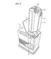
- lid 4 connected to the body in top panel 8 of housing 1, which is a lid that covers the opening as shown in Fig. 13, and to find the handle of container part 12 inside of the heater as well as to grasp the handle and lift up the container part in order to remove container part 12 from housing 1 for fuel refill.
- lid 4 it is necessary to manually close lid 4 connected to the body after container part 12 has been set inside of housing 1 in order to complete the replacement of container part 12 after container part 12 has been refilled with fuel.
- a joint part 47 for connecting a pipe for fuel transfer to the container part and a cushioned cover 120 for protecting joint part 47 at the time that the heater falls down are attached to the upper portion of container part 12. Therefore, joint part 47 and cushioned cover 120 are exposed from the top of the heater at the time when container part 12 is removed and they can easily be seen by the user, giving a negative impression to the user.
- the member above the container part may melt and hang down onto container part 12 and prevent the normal operation of the liquid supply device itself from continuing when, for example, a large amount of heat is conveyed to lid 4 connected to the body due to a problem outside of housing 1 causing the member above the container part to become melted and deformed.
- An object of a first invention is to provide a liquid supply device and a liquid fuel combustion apparatus wherein inconvenience to the user is reduced and which has a simple appearance.
- An object of a second invention is to provide a liquid supply device and a liquid fuel combustion apparatus wherein overheating of the container part does not affect the lid connected to the body of the liquid fuel combustion apparatus.
- an object of the second invention is to provide a liquid supply device and a liquid fuel combustion apparatus wherein the container part is not negatively affected even in the case where the lid connected to the body becomes thermally deformed or melts.
- a liquid supply device contained inside of the body of an apparatus having a top surface, for supplying liquid to the body of the apparatus in accordance with the operation of the body of the apparatus, includes: a container part that is freely removable/attachable from/to the predetermined attachment position inside of the body of the apparatus and that can store the liquid; and a top panel of the container part formed on the top surface of the container part, wherein the top panel of the container part covers the opening provided in the top surface of the body of the apparatus in order to contain the container part inside of the body of the apparatus when the container part is attached to the attachment position.
- the body of the apparatus that contains this liquid supply device has a form without any openings and has a simple appearance when this liquid supply device is attached at the attachment position.
- a liquid supply device contained inside of the body of an apparatus having a top surface, for supplying liquid to the body of the apparatus in accordance with the operation of the body of the apparatus, includes: a container part that is freely removable/attachable from/to the predetermined attachment position inside of the body of the apparatus and that can store the liquid; and a top panel of the container part formed on the top surface of the container part, wherein the top panel of the container part is located approximately at the same height as the top surface of the body of the apparatus when the container part is attached to the attachment position.
- the body of the apparatus that contains this liquid supply device has a form wherein the top of this liquid supply device appears unified with the top of the body of the apparatus and has a simple appearance when this liquid supply device is attached at the attachment position.
- the top panel of the container part is formed integrally with the container part.
- the container part and the upper panel of the container part are integrated and a lid connected to the body, which is separately provided in the prior art, becomes unnecessary according to this configuration in the body of the apparatus containing this liquid supply device. As a result, it becomes unnecessary for the user to open and close the lid connected to the body and, thus, labor is reduced.
- the top panel of the container part is provided with a handle to be held at the time that the container part is carried.
- the user can grasp the handle and can lift the liquid supply device, which includes the container part and, therefore, the utility is increased.
- the container part is provided with an opening for liquid through which the liquid enters the container part and the opening for liquid can be opened only under the condition that the container part is removed from the body of the apparatus.
- This liquid supply device in order to ensure safety according to the configuration.
- a liquid fuel combustion apparatus includes: a body of an apparatus having a top surface; and a liquid supply device, contained inside of the body of the apparatus having a top surface, for supplying liquid to the body of the apparatus in accordance with the operation of the body of the apparatus, wherein the liquid supply device includes: a container part that is freely removable/attachable from/to the predetermined attachment position inside of the body of the apparatus and that can store the liquid; and a top panel of the container part formed on the top surface of the container part, and the top panel of the container part covers the opening provided in the top surface of the body of the apparatus in order to contain the container part inside of the body of the apparatus when the container part is attached to the attachment position.
- the body of the apparatus that contains this liquid supply device has a form without any openings and has a simple appearance configuration when this liquid supply device is attached at the attachment position.
- a liquid fuel combustion apparatus includes: a body of an apparatus having a top surface; and a liquid supply device, contained inside of the body of the apparatus having a top surface, for supplying liquid to the body of the apparatus in accordance with the operation of the body of the apparatus, wherein the liquid supply device includes: a container part that is freely removable/attachable from/to the predetermined attachment position inside of the body of the apparatus and that can store the liquid; and a top panel of the container part formed on the top surface of the container part, and the top panel of the container part is located approximately at the same height as the top surface of the body of the apparatus when the container part is attached to the attachment position.
- the body of the apparatus that contains this liquid supply device has a form wherein the top of this liquid supply device appears unified with the top of the body of the apparatus and has a simple appearance when this liquid supply device is attached at the attachment position.
- the top panel of the container part is formed integrally with the container part.
- the container part and the upper panel of the container part are integrated and a lid connected to the body, which is separately provided in the prior art, becomes unnecessary according to this configuration in the body of the apparatus containing this liquid supply device. As a result, it becomes unnecessary for the user to open and close the lid connected to the body and, thus, labor is reduced.
- the top panel of the container part is provided with a handle to be held at the time that the container part is carried.
- the user can grasp the handle and can lift the liquid supply device, which includes the container part and, therefore, the utility is increased.
- the container part is provided with an opening for liquid through which the liquid enters the container part and the opening for liquid can be opened only under the condition that the container part is removed from the body of the apparatus.
- This liquid supply device in order to ensure safety according to the configuration.
- a liquid supply device contained inside of the body of an apparatus having a top surface, for supplying liquid to the body of the apparatus in accordance with the operation of the body of the apparatus, includes: a container part that is freely removable/attachable from/to the predetermined attachment position inside of the body of the apparatus and that can store the liquid; a top panel of the container part formed on the top surface of the container part; and a shielding body interposed between the container part and the top panel of the container part.
- the shielding body separates the container part from the entire surface of the top panel of the container part.
- the shielding body is made of heat insulating material.
- mutual transfer of heat between the container part and the top panel of the container part can be prevented and the top panel of the container part can be prevented from receiving negative effects from the container part when the container part is heated to a high temperature or the container part can be prevented from receiving negative effects from the top panel of the container part when the top panel of the container part is heated to a high temperature.
- a liquid fuel combustion apparatus includes: a body of an apparatus having a top surface; and a liquid supply device, contained inside of the body of the apparatus having a top surface, for supplying liquid to the body of the apparatus in accordance with the operation of the body of the apparatus, wherein the liquid supply device includes: a fuel container part that is freely removable/attachable from/to the predetermined attachment position inside of the body of the apparatus and that can store the liquid; a top panel of the fuel container part formed on the top surface of the fuel container part; and a shielding body interposed between the fuel container part and the top panel of the fuel container part.
- thermal interaction between the fuel container part and the top panel of the fuel container part as well as ignition of fuel inside of the fuel container part due to external heat can be prevented, and heat transfer to the top panel of the fuel container part due to excessive heat from the fuel container part can be prevented from causing the top panel of the fuel container part to melt and hang down or drop down through the selection of appropriate material for the shielding body according to this configuration.
- the shielding body separates the fuel container part from the entire surface of the top panel of the fuel container part.
- the top panel of the fuel container part can more surely be prevented from hanging down onto, or dropping down onto, the fuel container part in the case where the top panel of the fuel container part melts due to heat.
- the shielding body is made of heat insulating material.
- mutual transfer of heat between the fuel container part and the top panel of the fuel container part can be prevented, and the top panel of the fuel container part can be prevented from receiving negative effects from the fuel container part when the fuel container part is heated to a high temperature or the fuel container part can be prevented from receiving negative effects from the top panel of the fuel container part when the top panel of the fuel container part is heated to a high temperature.
- the shielding body is made of metal.
- the shielding body remains unchanged, without melting, and the melted top panel of the fuel container part can be prevented from hanging down onto, or dropping down onto, the fuel container part even in the case where the top panel of the fuel container part is made of resin and where the top panel of the fuel container part melts due to heat.
- the body of the apparatus includes a shielding wall on a side of a recess for containing the liquid supply device and the shielding body and the shielding wall contact each other so as to provide a structure that surrounds the fuel container part in a continuous manner when the liquid supply device is attached at the attachment position.
- the fuel container part of the liquid supply device is surrounded by the shielding wall on the side in addition to the shielding body on the top, wherein the shielding body and the shielding wall make contact with each other so as to surround the fuel container part in a continuous manner according to the configuration and, therefore, negative thermal effects can more surely be prevented and the top panel of the fuel container part can be prevented from hanging down onto, or dropping down onto, the fuel container part.
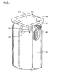
- a kerosene fan heater which is a liquid fuel combustion apparatus that uses the liquid supply device of the present invention, is described below with reference to Fig. 1 according to Embodiment 1 of the first invention.
- the same symbols are attached in the present embodiment to the same parts of the configuration as in the kerosene fan heater described in the prior art.
- a top panel 400 of the container part is secured to the top of container part 12 for integration with this liquid supply device.
- a handle 401 is provided to top panel 400 of the container part for the easy carrying of container part 12. Handle 401 folds into top panel 400 of the container part in the same plane at the time when not in utilization while handle 401 is lifted up from top panel 400 of the container part only at the time of utilization in this structure.
- top panel 400 of the container part is provided with a lid 402 above the kerosene refill opening that can be displaced so that top panel 400 of the container part is not a hindrance at the time of the refilling of fuel through supply opening 44. Lid 402 above the kerosene refill opening is also folded into top panel 400 of the container part in the same plane in the condition wherein the lid is closed in the structure.
- a joint part 47 and a cushioned cover 120 are placed in the upper portion of container part 12 in the same manner as in the prior art.
- a portion of the top surface of container part 12 is inclined and this inclined surface is provided with supply opening 44, through which liquid enters, and supply opening 44 is covered with a kerosene refill cap 39, also in the same manner as in the prior art.
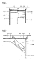
- Fig. 2 shows a cross sectional view of the condition wherein this liquid supply device is contained inside of housing 1.
- Top panel 400 of the container part is located at approximately the same height of the plane of top panel 8 of housing 1 and they form a continuous surface.
- top panel 400 of the container part has a structure so as to cover the opening in top panel 8.
- Fig. 3 shows a cross sectional view of the vicinity of supply opening 44 viewed from an angle different from that of Fig. 2.
- Supply opening 44 is provided with kerosene refill cap 39 in a structure wherein kerosene refill cap 39 cannot be opened when container part 12 is contained within housing 1 because supply opening 44 is provided in an inclined surface.
- Kerosene refill cap 39 can be opened only in the condition wherein container part 12 has been removed from housing 1.
- the liquid fuel combustion apparatus according to the present embodiment is a liquid fuel combustion apparatus provided with the above described liquid supply device and the appearance thereof is the same as that shown in Fig. 8.
- Top panel 400 of the container part is secured to container part 12 so as to be integrated with the above liquid supply device wherein top panel 400 of the container part has approximately the same height as the top surface of top panel 8 of housing 1 at the time when the liquid supply device is contained within housing 1 and, therefore, the top of this liquid supply device appears unified with the top of the fuel combustion apparatus and has a simple appearance.
- top panel 400 of the container part has a structure that covers the opening in top panel 8, wherein lid 4 connected to the body of the apparatus for the opening in top panel 8 becomes unnecessary, unlike in the prior art, and, therefore, it becomes unnecessary for the user to open and close lid 4 connected to the body of the apparatus.
- Handle 401 which becomes necessary at the time that the liquid supply device is removed from and reinserted into the apparatus, is provided so as to be folded, in the same plane, into top panel 400 of the container part and so as to be raised up from top panel 400 of the container part only at the time of utilization and, therefore, handle 401 is not a hindrance at the time when the handle is not being utilized and it can easily be raised up and grasped for the convenience of the user.
- Supply opening 44 is provided in the inclined surface of container part 12 in this structure wherein kerosene refill cap 39 cannot be opened when container part 12 is contained inside of housing 1 and, therefore, the situation wherein the refilling task is carried out while container part 12 is left inside of housing 1 due laziness or ignorance of the user can be avoided in order to ensure safety.
- joint part 47 and cushioned part 120 are hidden behind top panel 400 of the container part and, therefore, a negative impression in regard to the appearance can be avoided.
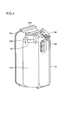
- FIG. 4 shows the condition of the structure before top panel 400 of the container part has been attached for ease of understanding.
- container part 12 is formed in approximately an approximately rectangular parallelepiped form wherein left member 12a, in approximately a plate form, of the kerosene supply tank and right member 12b, which is formed, by means of a press, into a container form having U-shaped cross section with the open end of the U shape facing to the left, of the kerosene supply tank are joined by means of an Adrian process.
- Container part 12 has an approximately rectangular form as viewed from above (in Fig. 4 above) and the right front corner, wherein joint part 47 is attached, is rounded.
- container part 12 does not match the shape of the opening in top panel 8 due to the above described corner rounding and container part 12 cannot be inserted into housing 1 in the case where the user attempts to insert container part 12 into the housing while holding container part 12 in the wrong direction. As a result of this, incorrect insertion can be prevented.
- the upper right rear portion of container part 12, in which supply opening 44 is provided has a form wherein the corner is cut off. The respective sides thereof are in R-shaped forms.
- Top panel 400 of the container part is secured with screws, or the like, to an attachment plate 403 for the top panel of the container part.
- liquid supply device is described herein with reference to an example wherein liquid fuel is supplied to a heating apparatus
- the liquid supply device according to the present invention is not limited to this application.
- the present invention is applicable in other apparatuses that hold some type of liquid.
- the invention is applicable to a humidifier, which is an apparatus that utilizes water as the liquid.
- a liquid supply device according to Embodiment 2 of the present invention is described below with reference to Fig. 5. Though the appearance of the liquid supply device is similar to that shown in Fig. 1, the bottom and the lower portions of the sides of top panel 400 of the container part are covered with a shielding plate 405a. On the other hand, the bottom and the lower portions of the sides of lid 402 above the kerosene refill opening are covered with a shielding plate 405b.
- Top panel 400 of the container part, handle 401 and lid 402 above the kerosene refill opening are all made of resin and shielding plates 405a and 405b are made of heat insulating material.
- this liquid supply device in the vicinity of top panel 400 of the container part at the time when this liquid supply device is within housing 1 is described with reference to Figs. 6 and 7.
- the inner sidewalls of the apparatus body that surrounding the space in which is placed the above described liquid supply device are covered with shielding walls 406 made of heat insulating material, as shown in Figs. 6 and 7, and shielding plates 405a and 405b and shielding walls 406 make contact with each other so as to surround container part 12 of the liquid supply device, which is contained in the apparatus body, in the condition wherein the liquid supply device is set within housing 1.
- Glass fiber, and the like, can be utilized as the heat insulating material that is formed into shielding plates 405a and 405b and shielding walls 406.
- top panel 400 of the container part and lid 402 above the kerosene refill opening are covered with shielding plates 405a and 405b and, therefore, heat that may be generated according to various reasons in container part 12 will not be transferred to top panel 400 of the container part or to lid 402 above the kerosene refill opening so that top panel 400 of the container part and lid 402 above the kerosene refill opening can be prevented from receiving thermal effects and prevented from melting or becoming thermally deformed even in the case where top panel 400 of the container part and lid 402 above the kerosene refill opening made of a resin that is susceptible to heat.
- container part 12 which is in the state of containment, is surrounded by shielding plates 405a and 405b and shielding walls 406 in the condition wherein the liquid supply device is within housing 1 and, therefore, effects from heat transfer can more surely be prevented.
- shielding plates 405a and 405b and shielding walls 406 make contact with each other so that container part 12 is surrounded in a continuous manner is preferable because this more surely prevents thermal effects.
- shielding plates 405a and 405b and shielding walls 406 are not limited to being made of heat insulating material but, rather, may be metal plates in the case where top panel 400 of the container part and lid 402 above the kerosene refill opening can be prevented from thermal deformation due to external heat and from hanging down onto, or dropping down onto, container part 12 as a result of becoming melted.
- Other fire retarding material may be used in place of metal plates.
- liquid supply device is described herein with reference to an example of a liquid supply device for supplying liquid fuel to a heating apparatus
- the liquid supply device according to the present invention is not limited to this application.
- the present invention is applicable in other apparatuses that hold some type of liquid.
- the invention is applicable to an apparatus that utilizes water as the liquid.
- a liquid supply device that stores water according to the invention is applicable to a humidifier.
- liquid supply device may be provided as a part in any apparatus that holds a liquid
- the application of the present invention to a liquid fuel combustion apparatus provided with an internal heat source wherein ignition of the internal fuel is not desired is advantageous because thermal interaction between the inside and the outside of the apparatus can be prevented.
- the top panel of the container part which also serves as a lid that is connected to the body of the apparatus according to a prior art, is secured to the container part for integration with the container part and, therefore, the container part and the top panel of the container part can be handled as a single unit, and the lid separately provided to the body of the apparatus according to the prior art becomes unnecessary. As a result, it becomes unnecessary for the user to open and close the lid connected to the body of the apparatus at the time of refill or exchange of the liquid and, thus, labor is reduced.
- the second invention provides a shielding body interposed between the container part and the top panel of the container part and, therefore, thermal interaction between the container part and the top panel of the container part can be prevented and the top panel of the container part can be prevented from melting and hanging down or dropping down through the selection of appropriate material for the shielding body.
- the ignition of fuel in the container part due to melting of the top panel of the container part caused by external heat can be prevented and the top panel of the container part can be prevented from becoming damaged due to abnormal heat emission from inside the container part.
- Both the first and second inventions are applicable to a liquid fuel combustion apparatus, such as a kerosene fan heater or a kerosene heater. Furthermore, the inventions are applicable to a liquid supply device, including a tank for storage of liquid, mounted in such an apparatus. In addition, the inventions are applicable to a liquid supply device provided in a humidifier, or the like.
Landscapes
- Engineering & Computer Science (AREA)
- Chemical & Material Sciences (AREA)
- Combustion & Propulsion (AREA)
- Mechanical Engineering (AREA)
- General Engineering & Computer Science (AREA)
- Physics & Mathematics (AREA)
- Thermal Sciences (AREA)
- Feeding And Controlling Fuel (AREA)
Abstract
Description
removable/attachable from/to the predetermined attachment position inside of the body of the apparatus and that can store the liquid; and a top panel of the container part formed on the top surface of the container part, wherein the top panel of the container part is located approximately at the same height as the top surface of the body of the apparatus when the container part is attached to the attachment position. With this configuration employed, the body of the apparatus that contains this liquid supply device has a form wherein the top of this liquid supply device appears unified with the top of the body of the apparatus and has a simple appearance when this liquid supply device is attached at the attachment position.
Claims (18)
- A liquid supply device, contained inside of the body of an apparatus having a top surface, for supplying liquid to said body of the apparatus in accordance with the operation of said body of the apparatus, said device comprising:a container part (12) that is freely removable/attachable from/to the predetermined attachment position inside of said body of the apparatus and that can store said liquid; anda top panel (400) of the container part formed on the top surface of said container part (12), whereinsaid top panel (400) of the container part covers the opening provided in the top surface of said body of the apparatus in order to contain said container part (12) inside of said body of the apparatus when said container part (12) is attached to said attachment position.
- A liquid supply device, contained inside of the body of an apparatus having a top surface, for supplying liquid to said body of the apparatus in accordance with the operation of said body of the apparatus, said device comprising:a container part (12) that is freely removable/attachable from/to the predetermined attachment position inside of said body of the apparatus and that can store said liquid; anda top panel (400) of the container part formed on the top surface of said container part (12), whereinsaid top panel (400) of the container part is located approximately at the same height as the top surface of said body of the apparatus when said container part (12) is attached to said attachment position.
- The liquid supply device according to claim 1, whereinsaid top panel (400) of the container part is formed integrally with said container part (12).
- The liquid supply device according to claim 1, whereinsaid top panel (400) of the container part is provided with a handle to be held at the time that said container part (12) is carried.
- The liquid supply device according to claim 1, whereinsaid container part (12) is provided with an opening for liquid through which said liquid enters said container part (12), and said opening for liquid can be opened only under the condition that said container part (12) is removed from said body of the apparatus.
- A liquid fuel combustion apparatus comprising:a body of an apparatus having a top surface; anda liquid supply device, contained inside of said body of the apparatus having a top surface, for supplying liquid to said body of the apparatus in accordance with the operation of said body of the apparatus, whereinsaid liquid supply device includes:a container part (12) that is freely removable/attachable from/to the predetermined attachment position inside of said body of the apparatus and that can store said liquid; anda top panel (400) of the container part formed on the top surface of said container part (12), andsaid top panel (400) of the container part covers the opening provided in the top surface of said body of the apparatus in order to contain said container part (12) inside of said body of the apparatus when said container part (12) is attached to said attachment position.
- A liquid fuel combustion apparatus comprising:a body of an apparatus having a top surface; anda liquid supply device, contained inside of said body of the apparatus having a top surface, for supplying liquid to said body of the apparatus in accordance with the operation of said body of the apparatus, whereinsaid liquid supply device includes:a container part (12) that is freely removable/attachable from/to the predetermined attachment position inside of said body of the apparatus and that can store said liquid; anda top panel (400) of the container part formed on the top surface of said container part (12), andsaid top panel (400) of the container part is located approximately at the same height as the top surface of said body of the apparatus when said container part (12) is attached to said attachment position.
- The liquid fuel combustion apparatus according to claim 6, whereinsaid top panel (400) of the container part is formed integrally with said container part (12).
- The liquid fuel combustion apparatus according to claim 6, whereinsaid top panel (400) of the container part is provided with a handle to be held at the time that said container part (12) is carried.
- The liquid fuel combustion apparatus according to claim 6, whereinsaid container part (12) is provided with an opening for liquid through which said liquid enters said container part (12) and, said opening for liquid can be opened only under the condition wherein said container part (12) is removed from said body of the apparatus.
- A liquid supply device, contained inside of the body of an apparatus having a top surface, for supplying liquid to said body of the apparatus in accordance with the operation of said body of the apparatus, said device comprising:a container part (12) that is freely removable/attachable from/to the predetermined attachment position inside of said body of the apparatus and that can store said liquid;a top panel (400) of the container part formed on the top surface of said container part (12); anda shielding body (405a, 405b) interposed between said container part (12) and said top panel (400) of the container part.
- The liquid supply device according to claim 11, whereinsaid shielding body (405a, 405b) separates said container part (12) from the entire surface of said top panel (400) of the container part.
- The liquid supply device according to claim 11, whereinsaid shielding body (405a, 405b) is made of heat insulating material.
- A liquid fuel combustion apparatus comprising:a body of an apparatus having a top surface; anda liquid supply device, contained inside of said body of the apparatus having a top surface, for supplying liquid to said body of the apparatus in accordance with the operation of said body of the apparatus, whereinsaid liquid supply device includes:a fuel container part that is freely removable/attachable from/to the predetermined attachment position inside of said body of the apparatus and that can store said liquid;a top panel of the fuel container part formed on the top surface of said fuel container part; anda shielding body (405a, 405b) interposed between said fuel container part and said top panel of the fuel container part.
- The liquid fuel combustion apparatus according to claim 14, whereinsaid shielding body (405a, 405b) separates said fuel container part from the entire surface of said top panel of the fuel container part.
- The liquid fuel combustion apparatus according to claim 14, whereinsaid shielding body (405a, 405b) is made of heat insulating material.
- The liquid fuel combustion apparatus according to claim 14, whereinsaid shielding body (405a, 405b) is made of metal.
- The liquid fuel combustion apparatus according to claim 14, whereinsaid body of the apparatus includes a shielding wall (406) on a side of a recess for containing said liquid supply device, and said shielding body (405a, 405b) and said shielding wall (406) contact each other so as to provide a structure that surrounds said fuel container part in a continuous manner when said liquid supply device is attached at said attachment position.
Applications Claiming Priority (5)
| Application Number | Priority Date | Filing Date | Title |
|---|---|---|---|
| JP2000393112A JP3866917B2 (en) | 2000-12-25 | 2000-12-25 | Liquid supply apparatus and liquid fuel combustion apparatus provided with the same |
| JP2000393112 | 2000-12-25 | ||
| JP2001141778 | 2001-05-11 | ||
| JP2001141778A JP3878819B2 (en) | 2001-05-11 | 2001-05-11 | Liquid fuel combustion equipment |
| PCT/JP2001/011220 WO2002052198A1 (en) | 2000-12-25 | 2001-12-20 | Liquid feeder and liquid fuel combustion device with the liquid feeder |
Publications (3)
| Publication Number | Publication Date |
|---|---|
| EP1347239A1 true EP1347239A1 (en) | 2003-09-24 |
| EP1347239A4 EP1347239A4 (en) | 2005-03-23 |
| EP1347239B1 EP1347239B1 (en) | 2006-11-22 |
Family
ID=26606547
Family Applications (1)
| Application Number | Title | Priority Date | Filing Date |
|---|---|---|---|
| EP01271851A Expired - Lifetime EP1347239B1 (en) | 2000-12-25 | 2001-12-20 | Liquid feeder and liquid fuel combustion device with the liquid feeder |
Country Status (4)
| Country | Link |
|---|---|
| EP (1) | EP1347239B1 (en) |
| CN (1) | CN1250904C (en) |
| ES (1) | ES2273777T3 (en) |
| WO (1) | WO2002052198A1 (en) |
Family Cites Families (5)
| Publication number | Priority date | Publication date | Assignee | Title |
|---|---|---|---|---|
| JPS55167042U (en) * | 1979-05-16 | 1980-12-01 | ||
| JPS5828221U (en) * | 1981-08-20 | 1983-02-23 | 株式会社東芝 | Heater with humidifier |
| JPS6441716A (en) * | 1987-08-05 | 1989-02-14 | Matsushita Electric Industrial Co Ltd | Liquid fuel supplying apparatus |
| JP3856570B2 (en) * | 1998-07-27 | 2006-12-13 | シャープ株式会社 | Liquid fuel combustion equipment |
| JP2000337625A (en) * | 1999-05-26 | 2000-12-08 | Matsushita Electric Ind Co Ltd | Oil burning equipment |
-
2001
- 2001-12-20 WO PCT/JP2001/011220 patent/WO2002052198A1/en not_active Ceased
- 2001-12-20 ES ES01271851T patent/ES2273777T3/en not_active Expired - Lifetime
- 2001-12-20 CN CN 01822841 patent/CN1250904C/en not_active Expired - Fee Related
- 2001-12-20 EP EP01271851A patent/EP1347239B1/en not_active Expired - Lifetime
Also Published As
| Publication number | Publication date |
|---|---|
| EP1347239A4 (en) | 2005-03-23 |
| ES2273777T3 (en) | 2007-05-16 |
| CN1492981A (en) | 2004-04-28 |
| CN1250904C (en) | 2006-04-12 |
| WO2002052198A1 (en) | 2002-07-04 |
| EP1347239B1 (en) | 2006-11-22 |
Similar Documents
| Publication | Publication Date | Title |
|---|---|---|
| US6104867A (en) | Method and apparatus for liquid vaporization | |
| US6594445B2 (en) | Heating device for the vaporization of active substances | |
| WO2020106070A1 (en) | Food receptacle using heating element | |
| KR101922975B1 (en) | Keeping warm device for gas container | |
| EP1347239A1 (en) | Liquid feeder and liquid fuel combustion device with the liquid feeder | |
| WO2010119816A1 (en) | Liquid tank and cooking device | |
| JPH03112600A (en) | Steam iron | |
| US6090036A (en) | Humidifying Mechanism for Incubator | |
| ITMI960486A1 (en) | DISTILLATION EQUIPMENT | |
| KR102431917B1 (en) | Heating type portable tumbler | |
| JP4076519B2 (en) | Electric water heater | |
| JP3878819B2 (en) | Liquid fuel combustion equipment | |
| KR20110024406A (en) | Rear cover of water purifier | |
| EP1609489B1 (en) | Electrical device for the release of active substances | |
| JP5329864B2 (en) | Battery case structure | |
| ES2226882T3 (en) | HEATING DEVICE. | |
| JP2002066199A (en) | Multipurpose steam generator | |
| JP2026003823A (en) | Beverage server | |
| JPS5820804Y2 (en) | cooking heating device | |
| JPH06253472A (en) | Uninterruptible power supply | |
| JPH0736589Y2 (en) | Kettle type liquid container | |
| JP4739513B2 (en) | Heating evaporator | |
| JP2001147011A (en) | Cartridge type refueling tank | |
| JPH10165307A (en) | Pump injection type liquid container | |
| JP5289789B2 (en) | Beverage supply equipment |
Legal Events
| Date | Code | Title | Description |
|---|---|---|---|
| PUAI | Public reference made under article 153(3) epc to a published international application that has entered the european phase |
Free format text: ORIGINAL CODE: 0009012 |
|
| 17P | Request for examination filed |
Effective date: 20030715 |
|
| AK | Designated contracting states |
Kind code of ref document: A1 Designated state(s): AT BE CH CY DE DK ES FI FR GB GR IE IT LI LU MC NL PT SE TR |
|
| RBV | Designated contracting states (corrected) |
Designated state(s): ES FR IT |
|
| REG | Reference to a national code |
Ref country code: DE Ref legal event code: 8566 |
|
| A4 | Supplementary search report drawn up and despatched |
Effective date: 20050203 |
|
| GRAP | Despatch of communication of intention to grant a patent |
Free format text: ORIGINAL CODE: EPIDOSNIGR1 |
|
| GRAS | Grant fee paid |
Free format text: ORIGINAL CODE: EPIDOSNIGR3 |
|
| GRAA | (expected) grant |
Free format text: ORIGINAL CODE: 0009210 |
|
| AK | Designated contracting states |
Kind code of ref document: B1 Designated state(s): ES FR IT |
|
| RAP1 | Party data changed (applicant data changed or rights of an application transferred) |
Owner name: SHARP KABUSHIKI KAISHA |
|
| REG | Reference to a national code |
Ref country code: ES Ref legal event code: FG2A Ref document number: 2273777 Country of ref document: ES Kind code of ref document: T3 |
|
| ET | Fr: translation filed | ||
| PLBE | No opposition filed within time limit |
Free format text: ORIGINAL CODE: 0009261 |
|
| STAA | Information on the status of an ep patent application or granted ep patent |
Free format text: STATUS: NO OPPOSITION FILED WITHIN TIME LIMIT |
|
| 26N | No opposition filed |
Effective date: 20070823 |
|
| PGFP | Annual fee paid to national office [announced via postgrant information from national office to epo] |
Ref country code: IT Payment date: 20101224 Year of fee payment: 10 |
|
| PGFP | Annual fee paid to national office [announced via postgrant information from national office to epo] |
Ref country code: ES Payment date: 20111228 Year of fee payment: 11 Ref country code: FR Payment date: 20111219 Year of fee payment: 11 |
|
| REG | Reference to a national code |
Ref country code: FR Ref legal event code: ST Effective date: 20130830 |
|
| PG25 | Lapsed in a contracting state [announced via postgrant information from national office to epo] |
Ref country code: FR Free format text: LAPSE BECAUSE OF NON-PAYMENT OF DUE FEES Effective date: 20130102 |
|
| PG25 | Lapsed in a contracting state [announced via postgrant information from national office to epo] |
Ref country code: IT Free format text: LAPSE BECAUSE OF NON-PAYMENT OF DUE FEES Effective date: 20121220 |
|
| REG | Reference to a national code |
Ref country code: ES Ref legal event code: FD2A Effective date: 20140307 |
|
| PG25 | Lapsed in a contracting state [announced via postgrant information from national office to epo] |
Ref country code: ES Free format text: LAPSE BECAUSE OF NON-PAYMENT OF DUE FEES Effective date: 20121221 |