EP1347199A1 - Method of manufacturing hydraulic shock absorber and production system for shock absorber in plant - Google Patents
Method of manufacturing hydraulic shock absorber and production system for shock absorber in plant Download PDFInfo
- Publication number
- EP1347199A1 EP1347199A1 EP01272870A EP01272870A EP1347199A1 EP 1347199 A1 EP1347199 A1 EP 1347199A1 EP 01272870 A EP01272870 A EP 01272870A EP 01272870 A EP01272870 A EP 01272870A EP 1347199 A1 EP1347199 A1 EP 1347199A1
- Authority
- EP
- European Patent Office
- Prior art keywords
- main body
- piston main
- piston
- shock absorber
- hydraulic shock
- Prior art date
- Legal status (The legal status is an assumption and is not a legal conclusion. Google has not performed a legal analysis and makes no representation as to the accuracy of the status listed.)
- Granted
Links
Images


Classifications
-
- F—MECHANICAL ENGINEERING; LIGHTING; HEATING; WEAPONS; BLASTING
- F16—ENGINEERING ELEMENTS AND UNITS; GENERAL MEASURES FOR PRODUCING AND MAINTAINING EFFECTIVE FUNCTIONING OF MACHINES OR INSTALLATIONS; THERMAL INSULATION IN GENERAL
- F16F—SPRINGS; SHOCK-ABSORBERS; MEANS FOR DAMPING VIBRATION
- F16F9/00—Springs, vibration-dampers, shock-absorbers, or similarly-constructed movement-dampers using a fluid or the equivalent as damping medium
- F16F9/32—Details
- F16F9/3207—Constructional features
- F16F9/3214—Constructional features of pistons
-
- B—PERFORMING OPERATIONS; TRANSPORTING
- B23—MACHINE TOOLS; METAL-WORKING NOT OTHERWISE PROVIDED FOR
- B23P—METAL-WORKING NOT OTHERWISE PROVIDED FOR; COMBINED OPERATIONS; UNIVERSAL MACHINE TOOLS
- B23P15/00—Making specific metal objects by operations not covered by a single other subclass or a group in this subclass
- B23P15/10—Making specific metal objects by operations not covered by a single other subclass or a group in this subclass pistons
-
- F—MECHANICAL ENGINEERING; LIGHTING; HEATING; WEAPONS; BLASTING
- F16—ENGINEERING ELEMENTS AND UNITS; GENERAL MEASURES FOR PRODUCING AND MAINTAINING EFFECTIVE FUNCTIONING OF MACHINES OR INSTALLATIONS; THERMAL INSULATION IN GENERAL
- F16F—SPRINGS; SHOCK-ABSORBERS; MEANS FOR DAMPING VIBRATION
- F16F9/00—Springs, vibration-dampers, shock-absorbers, or similarly-constructed movement-dampers using a fluid or the equivalent as damping medium
- F16F9/32—Details
- F16F9/34—Special valve constructions; Shape or construction of throttling passages
- F16F9/348—Throttling passages in the form of annular discs or other plate-like elements which may or may not have a spring action, operating in opposite directions or singly, e.g. annular discs positioned on top of the valve or piston body
- F16F9/3485—Throttling passages in the form of annular discs or other plate-like elements which may or may not have a spring action, operating in opposite directions or singly, e.g. annular discs positioned on top of the valve or piston body characterised by features of supporting elements intended to guide or limit the movement of the annular discs
-
- B—PERFORMING OPERATIONS; TRANSPORTING
- B23—MACHINE TOOLS; METAL-WORKING NOT OTHERWISE PROVIDED FOR
- B23P—METAL-WORKING NOT OTHERWISE PROVIDED FOR; COMBINED OPERATIONS; UNIVERSAL MACHINE TOOLS
- B23P2700/00—Indexing scheme relating to the articles being treated, e.g. manufactured, repaired, assembled, connected or other operations covered in the subgroups
- B23P2700/14—Suspension elements of automobile vehicles
-
- Y—GENERAL TAGGING OF NEW TECHNOLOGICAL DEVELOPMENTS; GENERAL TAGGING OF CROSS-SECTIONAL TECHNOLOGIES SPANNING OVER SEVERAL SECTIONS OF THE IPC; TECHNICAL SUBJECTS COVERED BY FORMER USPC CROSS-REFERENCE ART COLLECTIONS [XRACs] AND DIGESTS
- Y10—TECHNICAL SUBJECTS COVERED BY FORMER USPC
- Y10T—TECHNICAL SUBJECTS COVERED BY FORMER US CLASSIFICATION
- Y10T29/00—Metal working
- Y10T29/49—Method of mechanical manufacture
- Y10T29/49826—Assembling or joining
- Y10T29/49828—Progressively advancing of work assembly station or assembled portion of work
-
- Y—GENERAL TAGGING OF NEW TECHNOLOGICAL DEVELOPMENTS; GENERAL TAGGING OF CROSS-SECTIONAL TECHNOLOGIES SPANNING OVER SEVERAL SECTIONS OF THE IPC; TECHNICAL SUBJECTS COVERED BY FORMER USPC CROSS-REFERENCE ART COLLECTIONS [XRACs] AND DIGESTS
- Y10—TECHNICAL SUBJECTS COVERED BY FORMER USPC
- Y10T—TECHNICAL SUBJECTS COVERED BY FORMER US CLASSIFICATION
- Y10T29/00—Metal working
- Y10T29/49—Method of mechanical manufacture
- Y10T29/49826—Assembling or joining
- Y10T29/49828—Progressively advancing of work assembly station or assembled portion of work
- Y10T29/49829—Advancing work to successive stations [i.e., assembly line]
-
- Y—GENERAL TAGGING OF NEW TECHNOLOGICAL DEVELOPMENTS; GENERAL TAGGING OF CROSS-SECTIONAL TECHNOLOGIES SPANNING OVER SEVERAL SECTIONS OF THE IPC; TECHNICAL SUBJECTS COVERED BY FORMER USPC CROSS-REFERENCE ART COLLECTIONS [XRACs] AND DIGESTS
- Y10—TECHNICAL SUBJECTS COVERED BY FORMER USPC
- Y10T—TECHNICAL SUBJECTS COVERED BY FORMER US CLASSIFICATION
- Y10T29/00—Metal working
- Y10T29/49—Method of mechanical manufacture
- Y10T29/49826—Assembling or joining
- Y10T29/4984—Retaining clearance for motion between assembled parts
Definitions
- This invention relates to a method of manufacture for a hydraulic shock absorber and a factory production system therefor.
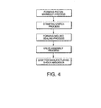
- a prior-art example of a method for manufacturing a piston assembly as shown in Fig. 4 comprises the sequence of a process of forming a piston main body by sintering, a process of stamping an orifice in the piston main body, a process of forming a molded sealing in the piston main body and a process of mounting a valve on the piston -main body.
- a piston assembly manufactured in the above manner is then transported to the hydraulic shock absorber manufacturing step.
- the piston assembly comprises a metallic piston main body provided with a rod through hole and formed by sintering, a throttle passage formed by a stamping process on the piston main body, a resinous molded sealing formed on the outer peripheral section of the piston main body and a valve mounted on the piston main body.
- the method of manufacturing comprises a piston main body manufacturing step comprising the sequence of a process of sintering the piston main body and a process of forming a molded sealing on the piston main body, a piston assembly manufacturing step comprising the sequence of a process of forming a throttle hydraulic passage in the piston main body and a process of mounting a valve on the piston main body and a hydraulic absorber manufacturing step in which a hydraulic shock absorber is manufactured using the piston assembly manufactured in the piston assembly manufacturing step.
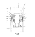
- a hydraulic shock absorber 1 comprises a rod 2 connected with respect to a vehicle body, a cylinder 3 connected with respect to a wheel shaft, a piston main body 5 connected to the rod 2 and partitioning the cylinder 3 into a lower oil chamber 17 and an upper oil chamber 16 which are filled with working oil, a valve 6 generates a damping force by an extension stroke at the extremely low speed, a main valve 8 which opens against a spring 9 during the extension stroke, a relief valve 7 which opens during a compression stroke and a plurality of orifices (throttle passages) 13 which are engraved into a seat 12 corresponding to the relief valve 7 of the piston main body 5.
- the hydraulic shock absorber 1 comprises a damping force generating mechanism for damping vibration from the vehicle wheels in the cylinder 3.
- the metallic piston main body 5 comprises a rod through hole 18 passing through the rod 2, an oil passage 19 and a seat 12. These components are formed by sintering.
- the orifice 13 is formed by a stamping process on the piston main body 5.
- a resinous molded sealing 14 is formed in the outer peripheral section of the piston main body 5.
- the piston assembly 10 When assembling the hydraulic shock absorber 1, the piston assembly 10 is formed by mounting valves 6 - 8 in the piston main body 5 having a molded sealing 14 and mounting the resulting device on the rod 2.
- the process 41 is performed by a manufacturing device forming the piston main body 5 with a sintering operation.
- the process 42 is performed by a manufacturing device forming the molded sealing 14 on the piston main body 5.
- the process 43 is performed by an orifice stamping machine.
- the process 44 is performed by a manufacturing device performing automatic assembly of the valves 6 ⁇ 8.
- manufacturing devices are provided in sequence to perform steps 21, 22, 23, 24 with the work being transported by hand between the steps 21 - 24.
- steps 21 - 24 it is also possible to connect the steps 21 - 24 using a conveyor so that the processes 41 - 44 are performed continuously.
- Fig.2 shows the movement of a work through the process 43 and the process 44.
- a plurality of piston main body units 5 having a molded sealing 14 formed thereon as shown in (a) in the figure are loaded onto a pallet 32 by inserting a pole 31 into the rod through hole 18.
- piston main body units 5 are taken from the pallet 43 on the pole 31 and loaded into an orifice stamping device.
- the piston main body units 5 are aligned and loaded onto a pallet 33 provided with a hole according to type by an automatic sorting device 34 as shown by (c) in the figure.
- valves 6 - 8 are assembled with the piston main body units 5 loaded by type onto the pallets 33 as shown by (d) in the figure in order to complete the piston assembly 10.
- the piston assemblies 10 loaded by type onto the pallets 33 are transported to a hydraulic shock absorber manufacturing step in which the hydraulic shock absorber 1 is assembled.
- the process 43 of forming the orifice 13 in the piston main body 5 is performed in sequence with the process 44 of assembling the valve 6 - 8 or the like in the piston main body 5, it is not necessary to provide for an intermediate inventory between the two processes 43, 44.
- the pallets 33 are designated with respect to the same type of piston assembly 10.
- the manufacturing process is performed efficiently due to the fact that the piston main body 5 manufactured in the process 42 are transported to the process 43 in a state of being inserted on the pole 31. This allows the pole 31 to be used to load the piston main body 5 into the orifice stamping device in the process 43.
- a method of manufacturing a hydraulic shock absorber and a factory production system therefor is useful as a factory production system and a method of manufacturing a hydraulic shock absorber used in an automobile.
- it is adapted for use as a factory production system and a method of manufacturing for mass production of a plurality of types of piston assembly
Landscapes
- Engineering & Computer Science (AREA)
- General Engineering & Computer Science (AREA)
- Mechanical Engineering (AREA)
- Fluid-Damping Devices (AREA)
Abstract
Description
- This invention relates to a method of manufacture for a hydraulic shock absorber and a factory production system therefor.
- In the prior art, the damping characteristics of a hydraulic shock absorber used in an automobile differ depending on the type of vehicle. Consequently it is necessary to manufacture a plurality of types of piston assembly from a single type of piston main body by varying the valves or the like mounted on the piston main body or by varying the shape or number of orifices stamped in the piston main body.
- A prior-art example of a method for manufacturing a piston assembly as shown in Fig. 4 comprises the sequence of a process of forming a piston main body by sintering, a process of stamping an orifice in the piston main body, a process of forming a molded sealing in the piston main body and a process of mounting a valve on the piston -main body. A piston assembly manufactured in the above manner is then transported to the hydraulic shock absorber manufacturing step.
- However in this type of prior-art hydraulic shock absorber manufacturing process, it is necessary to monitor inventory levels in the four manufacturing steps executing respective processes. Thus the problem arises that intermediate inventory availability must be increased. In particular, in the process after stamping the orifice into the piston main body, since a plurality of piston assembly types are produced as a result of the shape or the number of orifices, it is necessary to monitor a plurality of inventory levels in response to the piston assembly type. Consequently the problem arises that time is required to adapt to variations in the production level or to variations in product design.
- It is therefore an object of this invention to provide a system for a method of manufacturing a hydraulic shock absorber which is characterized by high productivity.
- It is a further object of this invention to provide a factory production system for a hydraulic shock absorber which is characterized by high productivity.
- This invention is adapted for use in a method of manufacturing a hydraulic shock absorber provided with a piston assembly. The piston assembly comprises a metallic piston main body provided with a rod through hole and formed by sintering, a throttle passage formed by a stamping process on the piston main body, a resinous molded sealing formed on the outer peripheral section of the piston main body and a valve mounted on the piston main body.
- The method of manufacturing comprises a piston main body manufacturing step comprising the sequence of a process of sintering the piston main body and a process of forming a molded sealing on the piston main body, a piston assembly manufacturing step comprising the sequence of a process of forming a throttle hydraulic passage in the piston main body and a process of mounting a valve on the piston main body and a hydraulic absorber manufacturing step in which a hydraulic shock absorber is manufactured using the piston assembly manufactured in the piston assembly manufacturing step.
- Since the process of forming the piston main body by sintering in the piston main body manufacturing step is performed in sequence with the step of forming the molded sealing in the piston main body, it is not necessary to provide for an intermediate inventory between the two steps. Furthermore inventory monitoring processes are simplified since it is not necessary to monitor inventory levels with respect to a plurality of piston assembly types with different valves or throttle hydraulic passages in the piston main body manufacturing step.
- Since the process of forming the throttle hydraulic passage in the piston main body in the piston assembly manufacturing step is performed in sequence with the step of assembling the valve or the like on the piston main body, it is not necessary to provide for an intermediate inventory between the two steps and thus it is possible to respond rapidly to variations in the production level or design variations in the product.
-
- Fig. 1 shows a process of manufacturing a preferred piston assembly according to this invention.
- Fig. 2 shows the movement of components through respective processes.
- Fig. 3 is a sectional view of a piston.
- Fig. 4 shows a production process for a piston assembly according to a prior-art example.
-
- In order to describe the invention in greater detail, the preferred embodiments will be outlined below with reference to the accompanying drawings.
- As shown in Fig. 3, a
hydraulic shock absorber 1 comprises arod 2 connected with respect to a vehicle body, acylinder 3 connected with respect to a wheel shaft, a pistonmain body 5 connected to therod 2 and partitioning thecylinder 3 into alower oil chamber 17 and an upper oil chamber 16 which are filled with working oil, avalve 6 generates a damping force by an extension stroke at the extremely low speed, amain valve 8 which opens against a spring 9 during the extension stroke, arelief valve 7 which opens during a compression stroke and a plurality of orifices (throttle passages) 13 which are engraved into a seat 12 corresponding to therelief valve 7 of the pistonmain body 5. Thus thehydraulic shock absorber 1 comprises a damping force generating mechanism for damping vibration from the vehicle wheels in thecylinder 3. - The metallic piston
main body 5 comprises a rod throughhole 18 passing through therod 2, anoil passage 19 and a seat 12. These components are formed by sintering. The orifice 13 is formed by a stamping process on the pistonmain body 5. A resinous molded sealing 14 is formed in the outer peripheral section of the pistonmain body 5. - When assembling the hydraulic shock absorber 1, the piston assembly 10 is formed by mounting valves 6 - 8 in the piston
main body 5 having a molded sealing 14 and mounting the resulting device on therod 2. - Since the damping characteristics required by the hydraulic shock absorber 1 for respective vehicles result in differences in the shape or number of orifices 13 stamped in the piston
main body 5 or difference in the valves 6 - 8 comprising the piston assembly 10, it is necessary to produce a plurality of types of piston assembly 10 based on a single type of pistonmain body 5. - Consequently as shown in Fig. 1, a factory production system according to this invention for producing piston assembly 10 comprises a
process 41 for forming the pistonmain body 5 by sintering, aprocess 42 for forming the molded sealing 14 on the sintered pistonmain body 5, aprocess 43 for stamping the orifice 13 into the pistonmain body 5 having a molded sealing 14 formed thereon and separating the works into types (component number) and aprocess 44 for automatic assembly of the valves 6 - 8 onto different types of pistonmain body 5 having an orifice 13 formed thereon. - The
process 41 is performed by a manufacturing device forming the pistonmain body 5 with a sintering operation. Theprocess 42 is performed by a manufacturing device forming the molded sealing 14 on the pistonmain body 5. Theprocess 43 is performed by an orifice stamping machine. Theprocess 44 is performed by a manufacturing device performing automatic assembly of thevalves 6―8. - In this aspect of this embodiment, manufacturing devices are provided in sequence to perform
steps - Fig.2 shows the movement of a work through the
process 43 and theprocess 44. In Fig. 2, a plurality of pistonmain body units 5 having a molded sealing 14 formed thereon as shown in (a) in the figure are loaded onto apallet 32 by inserting apole 31 into the rod throughhole 18. In theprocess 43, pistonmain body units 5 are taken from thepallet 43 on thepole 31 and loaded into an orifice stamping device. After an orifice 13 is stamped onto the pistonmain body 5 as shown by (b) in the figure, the pistonmain body units 5 are aligned and loaded onto apallet 33 provided with a hole according to type by anautomatic sorting device 34 as shown by (c) in the figure. In theprocess 44, valves 6 - 8 are assembled with the pistonmain body units 5 loaded by type onto thepallets 33 as shown by (d) in the figure in order to complete the piston assembly 10. The piston assemblies 10 loaded by type onto thepallets 33 are transported to a hydraulic shock absorber manufacturing step in which thehydraulic shock absorber 1 is assembled. - Since the
process 41 of forming the pistonmain body 5 by sintering is performed in sequence with theprocess 42 of forming the molded sealing 14 in the pistonmain body 5, it is not necessary to provide for an intermediate inventory between the twoprocesses processes - Furthermore since the
process 43 of forming the orifice 13 in the pistonmain body 5 is performed in sequence with theprocess 44 of assembling the valve 6 - 8 or the like in the pistonmain body 5, it is not necessary to provide for an intermediate inventory between the twoprocesses processes pallets 33 are designated with respect to the same type of piston assembly 10. Thus it is possible to perform efficient manufacture of a plurality of types of piston assembly 10 and to respond rapidly to variations in the production level or design variations in the product. - In addition, the manufacturing process is performed efficiently due to the fact that the piston
main body 5 manufactured in theprocess 42 are transported to theprocess 43 in a state of being inserted on thepole 31. This allows thepole 31 to be used to load the pistonmain body 5 into the orifice stamping device in theprocess 43. - Furthermore since the piston assembly 10 which are loaded by type onto the
pallets 33 are transported to the hydraulic shock absorber manufacturing step which assembles thehydraulic shock absorber 1, it is possible to perform efficient assembly of thehydraulic shock absorber 1 usingpallets 33 designated for different types in the hydraulic shock absorber manufacturing step. - Although the invention has been described above by reference to certain embodiments of the invention, the invention is not limited to the embodiments described above. Modifications and variations of the embodiments described above will occur to those skilled in the art, in the light of the above teachings.
- As shown above, a method of manufacturing a hydraulic shock absorber and a factory production system therefor according to this invention is useful as a factory production system and a method of manufacturing a hydraulic shock absorber used in an automobile. In particular, it is adapted for use as a factory production system and a method of manufacturing for mass production of a plurality of types of piston assembly
Claims (3)
- A method of manufacturing a hydraulic shock absorber, the hydraulic shock absorber provided with a piston assembly comprising a metallic piston main body having a rod through hole and formed by sintering; a throttle oil passage formed by stamping the piston main body, a resinous molded sealing formed on the outer periphery of the piston main body; and a valve mounted on the piston main body; the manufacturing method comprising:a piston main body manufacturing step in which the process of sintering of the piston main body and the process of forming of the molded sealing on the piston main body are performed in sequence;a piston assembly manufacturing step in which the process of forming of the throttle oil passage on the piston main body and the process of assembling of valves onto the piston main body are performed in sequence; anda hydraulic shock absorber manufacturing step for manufacturing a hydraulic shock absorber using the piston assembly manufactured in the piston assembly manufacturing step.
- The method of manufacturing a hydraulic shock absorber as defined in Claim 1, wherein a piston assembly is manufactured by a factory production system, the system comprising:a process of forming the piston main body by sintering;a process of forming the molded sealing on the sintered piston main body;a process of forming a throttle passage on the piston main body having a molded sealing formed thereon and sorting the piston main body units by type; anda process of assembling the valves by type with respect to piston main body units having a throttle oil passage formed thereon.
- The method of manufacturing a hydraulic shock absorber as defined by Claim 1, wherein a plurality of piston main body units manufactured in the piston main body manufacturing step are inserted onto a pole and transported to the piston assembly manufacturing step.
Applications Claiming Priority (5)
| Application Number | Priority Date | Filing Date | Title |
|---|---|---|---|
| JP2000398006A JP2002195333A (en) | 2000-12-27 | 2000-12-27 | Manufacturing method of hydraulic shock absorber |
| JP2000398006 | 2000-12-27 | ||
| JP2001009997 | 2001-01-18 | ||
| JP2001009997A JP2002213513A (en) | 2001-01-18 | 2001-01-18 | Factory production system of hydraulic shock absorber |
| PCT/JP2001/011455 WO2002053934A1 (en) | 2000-12-27 | 2001-12-26 | Method of manufacturing hydraulic shock absorber and production system for shock absorber in plant |
Publications (3)
| Publication Number | Publication Date |
|---|---|
| EP1347199A1 true EP1347199A1 (en) | 2003-09-24 |
| EP1347199A4 EP1347199A4 (en) | 2006-12-06 |
| EP1347199B1 EP1347199B1 (en) | 2007-11-28 |
Family
ID=26606858
Family Applications (1)
| Application Number | Title | Priority Date | Filing Date |
|---|---|---|---|
| EP01272870A Expired - Lifetime EP1347199B1 (en) | 2000-12-27 | 2001-12-26 | Method of manufacturing hydraulic shock absorber and production system for shock absorber in plant |
Country Status (5)
| Country | Link |
|---|---|
| US (1) | US7065852B2 (en) |
| EP (1) | EP1347199B1 (en) |
| DE (1) | DE60131679T2 (en) |
| ES (1) | ES2296707T3 (en) |
| WO (1) | WO2002053934A1 (en) |
Families Citing this family (3)
| Publication number | Priority date | Publication date | Assignee | Title |
|---|---|---|---|---|
| DE102008001472A1 (en) | 2008-04-30 | 2009-11-05 | Zf Friedrichshafen Ag | Metallic component such as valve/piston of shock absorber for motor vehicle, comprises a sintered material, and a base body with a through-hole, which is produced by stamping process and is introduced into a sintered blank of the base body |
| JP5850688B2 (en) * | 2011-09-28 | 2016-02-03 | 日立オートモティブシステムズ株式会社 | Cylinder device manufacturing method |
| DE102018112458B4 (en) * | 2018-05-24 | 2025-01-02 | Stabilus Gmbh | Method for producing a piston and piston |
Family Cites Families (7)
| Publication number | Priority date | Publication date | Assignee | Title |
|---|---|---|---|---|
| DE4110023A1 (en) * | 1991-03-27 | 1992-10-01 | Ringsdorff Werke Gmbh | SHOCK ABSORBER PISTON FROM UNEQUAL, JOINTED PARTS |
| EP0119197B1 (en) * | 1982-09-20 | 1988-11-02 | Ford Motor Company Limited | A rebound stop member for a telescopic hydraulic shock absorber |
| US4838394A (en) * | 1988-09-06 | 1989-06-13 | Lemme Charles D | Adjustable shock absorber and system |
| JPH07332423A (en) | 1994-06-03 | 1995-12-22 | Nippon Funmatsu Gokin Kk | Shock absorber piston |
| JPH07286639A (en) | 1994-10-31 | 1995-10-31 | Unisia Jecs Corp | Valve structure of hydraulic shock absorber |
| JPH1059473A (en) | 1996-08-26 | 1998-03-03 | Sony Corp | Logistics apparatus and method of using the same |
| JP2000257659A (en) | 1999-03-10 | 2000-09-19 | Showa Corp | Hydraulic shock absorber piston and piston oil passage forming method |
-
2001
- 2001-12-26 WO PCT/JP2001/011455 patent/WO2002053934A1/en not_active Ceased
- 2001-12-26 ES ES01272870T patent/ES2296707T3/en not_active Expired - Lifetime
- 2001-12-26 EP EP01272870A patent/EP1347199B1/en not_active Expired - Lifetime
- 2001-12-26 DE DE60131679T patent/DE60131679T2/en not_active Expired - Lifetime
- 2001-12-26 US US10/450,908 patent/US7065852B2/en not_active Expired - Lifetime
Non-Patent Citations (2)
| Title |
|---|
| No further relevant documents disclosed * |
| See also references of WO02053934A1 * |
Also Published As
| Publication number | Publication date |
|---|---|
| EP1347199B1 (en) | 2007-11-28 |
| EP1347199A4 (en) | 2006-12-06 |
| DE60131679T2 (en) | 2008-04-10 |
| WO2002053934A1 (en) | 2002-07-11 |
| US7065852B2 (en) | 2006-06-27 |
| US20040088850A1 (en) | 2004-05-13 |
| ES2296707T3 (en) | 2008-05-01 |
| DE60131679D1 (en) | 2008-01-10 |
Similar Documents
| Publication | Publication Date | Title |
|---|---|---|
| CN100453256C (en) | Method of manufacturing spring assembly | |
| KR101872982B1 (en) | Cylinder device | |
| US6659243B2 (en) | Shaft seat part structure of hydraulic shock absorber and assembling method thereof | |
| US7065852B2 (en) | Method of manufacturing hydraulic shock absorber and production system for shock absorber in plant | |
| US4371154A (en) | Spring assembly and method for manufacture thereof | |
| JP2004060634A (en) | Method for manufacturing crankshaft of hermetic reciprocating compressor | |
| US20120141304A1 (en) | Pump Housing for a Hydraulic Unit in a Motor Vehicle | |
| KR20190126813A (en) | Method for manufacturing pendulum damping device, and device obtained by this method | |
| US10309480B2 (en) | Hydraulic damper for a mount assembly | |
| EP3466558B1 (en) | Device for lightening the weight of crankshafts | |
| CN109154357A (en) | For connecting the connection component of multiple vibration damping block elements of damping block | |
| JP2002213513A (en) | Factory production system of hydraulic shock absorber | |
| JP2003083381A (en) | Hydraulic shock absorber tube structure and tube manufacturing method | |
| US9889715B2 (en) | Suspension member for a motor vehicle and method of forming the same | |
| JP2005188648A (en) | Hydraulic shock absorber knuckle bracket structure | |
| US20060015204A1 (en) | Method of manufacturing a modular damper | |
| JP2002195333A (en) | Manufacturing method of hydraulic shock absorber | |
| US20050204541A1 (en) | Method for manufacturing clutch housing | |
| CN212775447U (en) | Rubber shock absorber of engine | |
| KR20220046760A (en) | Apparatus and method for making flow path of piston valve for a shock absorber | |
| JPH0666343A (en) | Manufacture of fitting bracket for cylinder device | |
| JPH0191930A (en) | Production of piston base stock | |
| US20050238509A1 (en) | Clutch suction disk for air compressor of vehicle air conditioner | |
| JP4048083B2 (en) | Bump stopper | |
| JP2005180463A (en) | Valve guide pin for hydraulic shock absorber |
Legal Events
| Date | Code | Title | Description |
|---|---|---|---|
| PUAI | Public reference made under article 153(3) epc to a published international application that has entered the european phase |
Free format text: ORIGINAL CODE: 0009012 |
|
| 17P | Request for examination filed |
Effective date: 20030711 |
|
| AK | Designated contracting states |
Kind code of ref document: A1 Designated state(s): AT BE CH CY DE DK ES FI FR GB GR IE IT LI LU MC NL PT SE TR |
|
| RBV | Designated contracting states (corrected) |
Designated state(s): DE ES FR |
|
| A4 | Supplementary search report drawn up and despatched |
Effective date: 20061107 |
|
| GRAP | Despatch of communication of intention to grant a patent |
Free format text: ORIGINAL CODE: EPIDOSNIGR1 |
|
| RIN1 | Information on inventor provided before grant (corrected) |
Inventor name: SUDO, KIMIOC/O KAYABA INDUSTRY CO., LTD. Inventor name: UDA, RYUJIC/O KAYABA INDUSTRY CO., LTD. |
|
| GRAS | Grant fee paid |
Free format text: ORIGINAL CODE: EPIDOSNIGR3 |
|
| GRAA | (expected) grant |
Free format text: ORIGINAL CODE: 0009210 |
|
| AK | Designated contracting states |
Kind code of ref document: B1 Designated state(s): DE ES FR |
|
| REF | Corresponds to: |
Ref document number: 60131679 Country of ref document: DE Date of ref document: 20080110 Kind code of ref document: P |
|
| REG | Reference to a national code |
Ref country code: ES Ref legal event code: FG2A Ref document number: 2296707 Country of ref document: ES Kind code of ref document: T3 |
|
| ET | Fr: translation filed | ||
| PLBE | No opposition filed within time limit |
Free format text: ORIGINAL CODE: 0009261 |
|
| STAA | Information on the status of an ep patent application or granted ep patent |
Free format text: STATUS: NO OPPOSITION FILED WITHIN TIME LIMIT |
|
| 26N | No opposition filed |
Effective date: 20080829 |
|
| PGFP | Annual fee paid to national office [announced via postgrant information from national office to epo] |
Ref country code: ES Payment date: 20141111 Year of fee payment: 14 |
|
| PGFP | Annual fee paid to national office [announced via postgrant information from national office to epo] |
Ref country code: FR Payment date: 20141208 Year of fee payment: 14 |
|
| PGFP | Annual fee paid to national office [announced via postgrant information from national office to epo] |
Ref country code: DE Payment date: 20141223 Year of fee payment: 14 |
|
| REG | Reference to a national code |
Ref country code: DE Ref legal event code: R082 Ref document number: 60131679 Country of ref document: DE Representative=s name: GRUENECKER PATENT- UND RECHTSANWAELTE PARTG MB, DE Ref country code: DE Ref legal event code: R081 Ref document number: 60131679 Country of ref document: DE Owner name: KYB CORPORATION, JP Free format text: FORMER OWNER: KAYABA INDUSTRY CO., LTD., TOKYO, JP |
|
| REG | Reference to a national code |
Ref country code: FR Ref legal event code: CA Effective date: 20160321 Ref country code: FR Ref legal event code: CD Owner name: KYB CORPORATION, JP Effective date: 20160321 |
|
| REG | Reference to a national code |
Ref country code: DE Ref legal event code: R119 Ref document number: 60131679 Country of ref document: DE |
|
| REG | Reference to a national code |
Ref country code: FR Ref legal event code: ST Effective date: 20160831 |
|
| PG25 | Lapsed in a contracting state [announced via postgrant information from national office to epo] |
Ref country code: DE Free format text: LAPSE BECAUSE OF NON-PAYMENT OF DUE FEES Effective date: 20160701 |
|
| PG25 | Lapsed in a contracting state [announced via postgrant information from national office to epo] |
Ref country code: FR Free format text: LAPSE BECAUSE OF NON-PAYMENT OF DUE FEES Effective date: 20151231 |
|
| REG | Reference to a national code |
Ref country code: ES Ref legal event code: FD2A Effective date: 20170126 |
|
| PG25 | Lapsed in a contracting state [announced via postgrant information from national office to epo] |
Ref country code: ES Free format text: LAPSE BECAUSE OF NON-PAYMENT OF DUE FEES Effective date: 20151227 |