EP1347174B1 - Closed compressor - Google Patents
Closed compressor Download PDFInfo
- Publication number
- EP1347174B1 EP1347174B1 EP01271849A EP01271849A EP1347174B1 EP 1347174 B1 EP1347174 B1 EP 1347174B1 EP 01271849 A EP01271849 A EP 01271849A EP 01271849 A EP01271849 A EP 01271849A EP 1347174 B1 EP1347174 B1 EP 1347174B1
- Authority
- EP
- European Patent Office
- Prior art keywords
- leaf spring
- cylinder
- cylinder head
- intake muffler
- intake
- Prior art date
- Legal status (The legal status is an assumption and is not a legal conclusion. Google has not performed a legal analysis and makes no representation as to the accuracy of the status listed.)
- Expired - Lifetime
Links
Images


Classifications
-
- F—MECHANICAL ENGINEERING; LIGHTING; HEATING; WEAPONS; BLASTING
- F04—POSITIVE - DISPLACEMENT MACHINES FOR LIQUIDS; PUMPS FOR LIQUIDS OR ELASTIC FLUIDS
- F04B—POSITIVE-DISPLACEMENT MACHINES FOR LIQUIDS; PUMPS
- F04B39/00—Component parts, details, or accessories, of pumps or pumping systems specially adapted for elastic fluids, not otherwise provided for in, or of interest apart from, groups F04B25/00 - F04B37/00
-
- F—MECHANICAL ENGINEERING; LIGHTING; HEATING; WEAPONS; BLASTING
- F04—POSITIVE - DISPLACEMENT MACHINES FOR LIQUIDS; PUMPS FOR LIQUIDS OR ELASTIC FLUIDS
- F04B—POSITIVE-DISPLACEMENT MACHINES FOR LIQUIDS; PUMPS
- F04B39/00—Component parts, details, or accessories, of pumps or pumping systems specially adapted for elastic fluids, not otherwise provided for in, or of interest apart from, groups F04B25/00 - F04B37/00
- F04B39/0027—Pulsation and noise damping means
- F04B39/0055—Pulsation and noise damping means with a special shape of fluid passage, e.g. bends, throttles, diameter changes, pipes
- F04B39/0072—Pulsation and noise damping means with a special shape of fluid passage, e.g. bends, throttles, diameter changes, pipes characterised by assembly or mounting
-
- Y—GENERAL TAGGING OF NEW TECHNOLOGICAL DEVELOPMENTS; GENERAL TAGGING OF CROSS-SECTIONAL TECHNOLOGIES SPANNING OVER SEVERAL SECTIONS OF THE IPC; TECHNICAL SUBJECTS COVERED BY FORMER USPC CROSS-REFERENCE ART COLLECTIONS [XRACs] AND DIGESTS
- Y10—TECHNICAL SUBJECTS COVERED BY FORMER USPC
- Y10S—TECHNICAL SUBJECTS COVERED BY FORMER USPC CROSS-REFERENCE ART COLLECTIONS [XRACs] AND DIGESTS
- Y10S181/00—Acoustics
- Y10S181/403—Refrigerator compresssor muffler
Definitions
- This invention relates to a hermetic compressor used on a refrigerant cycle such as a refrigerator.
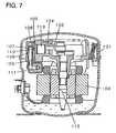
- Fig. 7 is a longitudinal cross-sectional view, illustrating the conventional compressor.
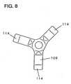
- Fig. 8 is a plan view, illustrating an elastic member for use on the compressor.
- a hermetic vessel 101 hermetically contains therein a compression element 102 and an electrically operated element 103.
- the compression element 102 includes a cylinder block 105 that forms a cylinder 104, a valve plate 106 for sealing the cylinder 104, an intake muffler 111, and a piston 113 reciprocated in the cylinder 104 by rotation of a shaft 112 that is secured to the electrically operated element 103.
- the intake muffler 111 is formed of resin, and has an end 107 positioned toward the cylinder and pressed against a gasket 110 through an irregularly deformed spring 109 around an intake orifice of the valve plate 106 by means of a thrust force of a cylinder head 108.
- the gasket 110 is disposed on a surface of the valve plate 106.
- the spring 109 has spring distal ends 114 positioned in respective concaves (not shown) of the intake muffler 111.
- the concaves (not shown) are provided in the intake muffler 111 at the end 107 thereof toward the cylinder.
- the cylinder head 108 contains the end 107 of the intake muffler 111, with the spring distal ends 114 being engaged with the intake muffler 111.
- a refrigerant gas returned to the compressor from a refrigerant cycle is released into the hermetic vessel 101.
- the refrigerant gas is then guided into the cylinder 104 after passing through the intake muffler 111 and the valve plate 106 that forms the compression element 102.
- the piston 113 that is driven by the electrically operated element 103 through the shaft 112 compresses the refrigerant gas.
- the compressed refrigerant gas is again fed through the valve plate 106, and is then discharged into the refrigerant cycle without being released into the hermetic vessel 101.
- the leaf spring Since the above-described conventional structure uses an irregularly deformed leaf spring as anelastic means the leaf spring must be positioned in a proper direction during compressor assembly. In addition, the irregularly deformed leaf spring must be positioned within fine limits because the respective ends of the leaf spring must be received in the concaves of the intake muffler at the end thereof toward the cylinder. This causes a disadvantage of a reduction in productivity due to difficulties in positioning the leaf spring in the process of the compressor assembly. Another drawback to the above conventional structure is that the shape of the irregularly deformed leaf spring is too complicated to provide an inexpensive compressor
- an object of the present invention is to provide an inexpensive, silently running hermetic compressor including a simply shaped leaf spring, which compressor is designed to provide smooth assembly without fine positioning of the leaf spring, and further to reliably press an orifice end of an intake muffler toward a cylinder against an intake port of a valve plate.
- the present invention comprises: a compression element placed in a hermetic vessel; a cylinder block including a cylinder that forms the compression element; a valve plate including an intake port, the valve plate being disposed on the cylinder at an opening end thereof; a cylinder head rigidly secured to the valve plate opposite to the cylinder; an intake muffler having an outlet positioned in a concave of the cylinder headf, and further having an orifice of the outlet provided at a distal end of the intake muffler and opened to the intake port; and a substantially disk-like elastic member disposed between the outlet and the cylinder head, wherein the outlet orifice of the intake muffler constantly remains pressed against the intake port.
- Such a nearly disk-like shape of the elastic member provides an operation in which the elastic member can be readily attached without being positioned within fine limits irrespective of where the elastic member is oriented when the intake muffler is assembled onto the compressor.
- the semi-disk shape of the elastic member provides another operation that a simply shaped elastic member is available at an inexpensive price.
- the elastic member includes a substantially donut-like leaf spring loosely engaged with a protrusion that is provided on either a rear surface of the intake muffler at the outlet orifice of the intake muffler or an inner surface of the cylinder head at the concave of the cylinder head.
- the elastic member can readily be attached between the rear surface of the intake muffler at the outlet orifice thereof and the inner surface of the cylinder head at the concave thereof.
- This construction provides an operation in which the protrusion serves as a guide to provide efficient assembly without fine positioning of the elastic member.
- the leaf spring has a curvilinear surface.
- This configuration causes both a bending center of the leaf spring and ends of the leaf spring to always remain pressed against either the rear surface of the intake muffler at the orifice end of the intake muffler toward the cylinder or the inner surface of the cylinder head at the concave of the cylinder head.
- This construction provides an operation in which assembly can be completed without fine positioning of the elastic means irrespective of where the elastic means is directed during compressor assembly.
- the leaf spring has peripheral portions bent toward the cylinder head, and ends of the leaf spring are held in linear contact with the cylinder head. This construction provides an operation in which the cylinder head is isolated from scoring and wear.
- the substantially disk-like elastic means is a waved elastic member bent in a direction of the circumference thereof, and an area of contact between the cylinder head and the intake muffler can be increased while a sufficient elastic force is retained. As a result, the cylinder head and the intake muffler are free from scoring and wear.
- Fig. 1 is a cross-sectional view, illustrating an essential portion of a hermetic compressor according to embodiment 1.
- Fig. 2 is an enlarged view, illustrating respective essential portions of an intake muffler and a substantially disk-like leaf spring, which are used on the hermetic compressor.
- a hermetic vessel 1 contains therein a compression element 2 and an electrically actuated element 3 in a gas tight manner.
- the compression element 2 includes a shaft 7 rigidly secured to the electrically actuated element 3, a piston 5 reciprocated in a cylinder 4 by rotation of the shaft 7 through a connecting rod 8, a valve plate 9 for sealing the cylinder 4, and an intake muffler 6 elastically fixed to the valve plate 9 by means of an inner wall of the cylinder head 11 through a substantially disk-like leaf spring 10.
- the intake muffler 6 is preferably a synthetic resin material having a high adiabatic effect, such as PBT (Polybutylene Terephtalate) or PPS (Polyphenylene Sulfide), in view of a situation in which the intake muffler 6 is subjected to elevated temperature in a refrigerator oil atmosphere as well as a refrigerant gas.
- the leaf spring 10 is primarily made of either steel material for use as a spring or a cold-rolled steel band for use as a spring.
- a refrigerant gas returned from a refrigerant cycle is released into the hermetic vessel 1.
- the refrigerant gas (not shown) is then guided into the cylinder 4 after passing through the intake muffler 6 and the valve plate 9 that forms the compression element 2.
- the piston 5 that is driven by the electrically operated element 3 through the shaft 7 compresses the refrigerant gas.
- the compressed refrigerant gas is again fed through the valve plate 9, and is then discharged into the refrigerant cycle without being released into the hermetic vessel 1.
- the leaf spring 10 forms a substantially disk shape that ignores directionality of the leaf spring 10 during assembly of the cylinder head 11. This feature eliminates laborious operations that involve a great deal of effort, such as fine positioning of the leaf spring 10 and an operation to have the leaf spring 10 oriented in a proper direction. As a result, improved productivity is achievable.
- Fig. 3 is an exploded perspective view of an intake muffler 6 and a substantially disk-like leaf spring which are used in a hermetic compressor according to embodiment 2.
- reference numeral 13 denotes a protrusion provided on the intake muffler 6 at the end 12 toward the cylinder.
- the protrusion 13 is loosely engaged with a lightening hole 14 of the leaf spring 10.
- the cylinder head 11 presses the end 12 of the muffler 6 against the gasket 15 through the leaf spring 10, thereby elastically fixing the end 12 to the gasket 15.
- the protrusion 13 is disposed on the muffler 6 at the end 12 toward the cylinder, but may alternatively be provided on an internal surface of the cylinder head 11.
- the leaf spring 10 elastically fixes the intake muffler 6 to the cylinder head 11, and thus eliminates rattles of the intake muffler 6 which otherwise would occur when reciprocating motion of the piston 5 vibrates the compression element 2. As a result, problems such as the occurrence of wear and that of noise due to the rattles can be avoided.
- the leaf spring 10 has a nearly disk shape that neglects directionality of the leaf spring 10 during assembly of the cylinder head 11. This feature eliminates laborious operations such as fine positioning of the leaf spring 10 and an operation to have the leaf spring 10 directed in a proper direction, and thus provides improved productivity.
- Fig. 4 is an enlarged perspective view of another leaf spring according to embodiment 2.
- reference numeral 16 denotes a leaf spring having a curvilinear surface. Such a leaf spring shape allows for compressor assembly regardless of where the leaf spring is oriented.
- Fig. 5 is an enlarged perspective view of a further leaf spring according to embodiment 2.
- reference numeral 17 denotes a leaf spring having peripheral portions 17a bent toward the cylinder head. As a result, ends of the leaf spring 17 are held in linear contact with the cylinder, thereby isolating the cylinder head from scoring and wear.
- Fig. 6 is an enlarged perspective view of a yet further leaf spring according to embodiment 2.
- reference numeral 18 denotes a serrated leaf spring circumferentially bent in a sinusoidal manner. This configuration is possible to sufficiently ensure an area of contact between the cylinder head and the intake muffler. As a result, the cylinder head and intake muffler are isolated from scoring and wear.
- the present invention comprises: a compression element placed in a hermetic vessel; a cylinder block including a cylinder that forms the compression element; a valve plate including an intake port, the valve plate being disposed on the cylinder at an opening end thereof; a cylinder head rigidly secured to the valve plate opposite to the cylinder; an intake muffler having an outlet positioned in the cylinder head at a concave thereof, and further having an orifice of the outlet provided at a distal end of the intake muffler and opened to the intake port; and a substantially disk-like elastic member disposed between the outlet and the cylinder head, wherein the outlet orifice of the intake muffler always remains pressed against the intake port.
- the intake muffler can elastically be fixed without being rattled. This feature makes it feasible to provide a low noise, low cost compressor with improved productivity.
- the elastic member includes a substantially donut-like leaf spring loosely engaged with a protrusion that is provided on either a rear surface of the intake muffler at the outlet orifice of the intake muffler or an inner surface of the cylinder head at the concave of the cylinder head.
- the leaf spring is provided with a curvilinear surface.
- This configuration causes both a bending center of the leaf spring and ends of the leaf spring to always remain pressed against either the rear surface of the intake muffler at the orifice end of the intake muffler toward the cylinder or the inner surface of the cylinder head at the concave of the cylinder head. Consequently, required spring characteristics are achievable in a stable manner, even with a small leaf spring.
- the leaf spring is usable on a small-sized compressor such as a refrigerator-dedicated compressor that is designed for use in a highly limited accommodation space.
- the leaf spring has peripheral portions bent toward the cylinder head, and ends of the leaf spring are held in linear contact with the cylinder head.
- the substantially disk-like elastic means is a serrated leaf spring circumferentially bent in a sinusoidal fashion.
Landscapes
- Engineering & Computer Science (AREA)
- Mechanical Engineering (AREA)
- General Engineering & Computer Science (AREA)
- Compressor (AREA)
- Compressors, Vaccum Pumps And Other Relevant Systems (AREA)
Description
- This invention relates to a hermetic compressor used on a refrigerant cycle such as a refrigerator.
- In recent years, a hermetic compressor designed to run silently has highly been required.
- In conventional hermetic compressors, an irregularly deformed elastic means has been employed, which must be positioned within fine limits when an intake muffler is fixed to the compressor. One such example of a conventional hermetic compressor is disclosed in published Japanese Patent Application Laid-Open No. 62-271974.
- The conventional hermetic compressor as discussed above will now be described with reference to the drawings. Fig. 7 is a longitudinal cross-sectional view, illustrating the conventional compressor. Fig. 8 is a plan view, illustrating an elastic member for use on the compressor. In Figs. 7 and 8, a
hermetic vessel 101 hermetically contains therein acompression element 102 and an electrically operatedelement 103. Thecompression element 102 includes acylinder block 105 that forms acylinder 104, avalve plate 106 for sealing thecylinder 104, anintake muffler 111, and apiston 113 reciprocated in thecylinder 104 by rotation of a shaft 112 that is secured to the electrically operatedelement 103. Theintake muffler 111 is formed of resin, and has anend 107 positioned toward the cylinder and pressed against agasket 110 through an irregularly deformedspring 109 around an intake orifice of thevalve plate 106 by means of a thrust force of acylinder head 108. Thegasket 110 is disposed on a surface of thevalve plate 106. Thespring 109 has springdistal ends 114 positioned in respective concaves (not shown) of theintake muffler 111. The concaves (not shown) are provided in theintake muffler 111 at theend 107 thereof toward the cylinder. Thecylinder head 108 contains theend 107 of theintake muffler 111, with the springdistal ends 114 being engaged with theintake muffler 111. - A description will now be made as to how the hermetic compressor as structured above (hereinafter called a compressor) operates.
- A refrigerant gas returned to the compressor from a refrigerant cycle is released into the
hermetic vessel 101. The refrigerant gas is then guided into thecylinder 104 after passing through theintake muffler 111 and thevalve plate 106 that forms thecompression element 102. In thecylinder 104, thepiston 113 that is driven by the electrically operatedelement 103 through the shaft 112 compresses the refrigerant gas. The compressed refrigerant gas is again fed through thevalve plate 106, and is then discharged into the refrigerant cycle without being released into thehermetic vessel 101. - At that time, pressure pulsing that results from intermittent compression caused by reciprocating motion of the
piston 113 partially flows back to theintake muffler 111. However, theinlake muffler 111 attenuates the pressure pulsing before the attenuated pressure pulsing is released into thehermetic vessel 101 because thegasket 110 impermeably seals theintake muffler 111 at theend 107 thereof toward the cylinder. As a result, noise can be reduced. The irregularly deformedspring 109 elastically fixes theintake muffler 111 to thecylinder head 108, thereby eliminating rattles of theintake muffler 111 which otherwise would occur when the reciprocating motion of thepiston 113 vibrates thecompression element 102. As a result, a highly reliable, low noise compressor is achievable. - Since the above-described conventional structure uses an irregularly deformed leaf spring as anelastic means the leaf spring must be positioned in a proper direction during compressor assembly. In addition, the irregularly deformed leaf spring must be positioned within fine limits because the respective ends of the leaf spring must be received in the concaves of the intake muffler at the end thereof toward the cylinder. This causes a disadvantage of a reduction in productivity due to difficulties in positioning the leaf spring in the process of the compressor assembly. Another drawback to the above conventional structure is that the shape of the irregularly deformed leaf spring is too complicated to provide an inexpensive compressor
- Reference can also be made to document WO 98/22712 which discloses a refrigerant compressor having an elastic member made for example of a bent metal leaf.
- In order to solve problems heretofore encountered, an object of the present invention is to provide an inexpensive, silently running hermetic compressor including a simply shaped leaf spring, which compressor is designed to provide smooth assembly without fine positioning of the leaf spring, and further to reliably press an orifice end of an intake muffler toward a cylinder against an intake port of a valve plate.
- The present invention comprises: a compression element placed in a hermetic vessel; a cylinder block including a cylinder that forms the compression element; a valve plate including an intake port, the valve plate being disposed on the cylinder at an opening end thereof; a cylinder head rigidly secured to the valve plate opposite to the cylinder; an intake muffler having an outlet positioned in a concave of the cylinder headf, and further having an orifice of the outlet provided at a distal end of the intake muffler and opened to the intake port; and a substantially disk-like elastic member disposed between the outlet and the cylinder head, wherein the outlet orifice of the intake muffler constantly remains pressed against the intake port. Such a nearly disk-like shape of the elastic member provides an operation in which the elastic member can be readily attached without being positioned within fine limits irrespective of where the elastic member is oriented when the intake muffler is assembled onto the compressor. The semi-disk shape of the elastic member provides another operation that a simply shaped elastic member is available at an inexpensive price.
- According to the present invention, the elastic member includes a substantially donut-like leaf spring loosely engaged with a protrusion that is provided on either a rear surface of the intake muffler at the outlet orifice of the intake muffler or an inner surface of the cylinder head at the concave of the cylinder head. As a result, the elastic member can readily be attached between the rear surface of the intake muffler at the outlet orifice thereof and the inner surface of the cylinder head at the concave thereof. This construction provides an operation in which the protrusion serves as a guide to provide efficient assembly without fine positioning of the elastic member.
- According to the present invention, the leaf spring has a curvilinear surface. This configuration causes both a bending center of the leaf spring and ends of the leaf spring to always remain pressed against either the rear surface of the intake muffler at the orifice end of the intake muffler toward the cylinder or the inner surface of the cylinder head at the concave of the cylinder head. This construction provides an operation in which assembly can be completed without fine positioning of the elastic means irrespective of where the elastic means is directed during compressor assembly.
- According to the present invention, the leaf spring has peripheral portions bent toward the cylinder head, and ends of the leaf spring are held in linear contact with the cylinder head. This construction provides an operation in which the cylinder head is isolated from scoring and wear.
- According to the present invention, the substantially disk-like elastic means is a waved elastic member bent in a direction of the circumference thereof, and an area of contact between the cylinder head and the intake muffler can be increased while a sufficient elastic force is retained. As a result, the cylinder head and the intake muffler are free from scoring and wear.
- The above objects and features of the present invention will become apparent in the following description of embodiments and the accompanying drawings in which:
- Fig. 1 is a longitudinal cross-sectional view, showing a hermetic compressor according to
embodiment 1 of the present invention; - Fig. 2 is an enlarged, cross-sectional view, illustrating an essential portion of the compressor;
- Fig. 3 is an exploded perspective view, illustrating an intake muffler and a substantially disk-like leaf spring according to
embodiment 2; - Fig. 4 is an enlarged perspective view, illustrating a leaf spring according to
embodiment 2; - Fig. 5 is an enlarged perspective view, illustrating another leaf spring according to
embodiment 2; - Fig. 6 is an enlarged perspective view, illustrating a further leaf spring according to
embodiment 2; - Fig. 7 is a longitudinal cross-sectional view, illustrating a prior art hermetic compressor; and
- Fig. 8 is a plan view, showing an elastic member used on the prior art compressor.
- Embodiments of a hermetic compressor according to the present invention will now be described with reference to the drawings. The same component elements as those in the related art are identified by the same reference characters, and detailed descriptions thereof will herein be omitted.
- Fig. 1 is a cross-sectional view, illustrating an essential portion of a hermetic compressor according to
embodiment 1. Fig. 2 is an enlarged view, illustrating respective essential portions of an intake muffler and a substantially disk-like leaf spring, which are used on the hermetic compressor. - In Figs. 1 and 2, a
hermetic vessel 1 contains therein acompression element 2 and an electrically actuatedelement 3 in a gas tight manner. Thecompression element 2 includes ashaft 7 rigidly secured to the electrically actuatedelement 3, apiston 5 reciprocated in a cylinder 4 by rotation of theshaft 7 through a connecting rod 8, avalve plate 9 for sealing the cylinder 4, and anintake muffler 6 elastically fixed to thevalve plate 9 by means of an inner wall of thecylinder head 11 through a substantially disk-like leaf spring 10. Theintake muffler 6 is preferably a synthetic resin material having a high adiabatic effect, such as PBT (Polybutylene Terephtalate) or PPS (Polyphenylene Sulfide), in view of a situation in which theintake muffler 6 is subjected to elevated temperature in a refrigerator oil atmosphere as well as a refrigerant gas. In view of a required shape, spring characteristics and cost, theleaf spring 10 is primarily made of either steel material for use as a spring or a cold-rolled steel band for use as a spring. - A description will now be made as to how the compressor as constructed above operates.
- A refrigerant gas returned from a refrigerant cycle is released into the
hermetic vessel 1. The refrigerant gas (not shown) is then guided into the cylinder 4 after passing through theintake muffler 6 and thevalve plate 9 that forms thecompression element 2. In the cylinder 4, thepiston 5 that is driven by the electrically operatedelement 3 through theshaft 7 compresses the refrigerant gas. The compressed refrigerant gas is again fed through thevalve plate 9, and is then discharged into the refrigerant cycle without being released into thehermetic vessel 1. - At this time, pressure pulsing that results from intermittent compression caused by reciprocating motion of the
piston 5 partially flows back to theintake muffler 6. However, theintake muffler 6 attenuates the pressure pulsing before the attenuated pressure pulsing is released into thehermetic vessel 1 because agasket 15 impermeably seals anend 12 of theintake muffler 6 toward the cylinder. As a result, reduced noise is attainable. In addition, the substantially disk-like spring 10 elastically fixes themuffler 6 to thecylinder head 11, thereby eliminating rattles of theintake muffler 6, which otherwise would occur when the reciprocating motion of thepiston 5 vibrates thecompression element 2. As a result, problems such as the occurrence of wear and that of noise due to the rattles can be obviated. - Furthermore, the
leaf spring 10 forms a substantially disk shape that ignores directionality of theleaf spring 10 during assembly of thecylinder head 11. This feature eliminates laborious operations that involve a great deal of effort, such as fine positioning of theleaf spring 10 and an operation to have theleaf spring 10 oriented in a proper direction. As a result, improved productivity is achievable. - Fig. 3 is an exploded perspective view of an
intake muffler 6 and a substantially disk-like leaf spring which are used in a hermetic compressor according toembodiment 2. In Fig. 3,reference numeral 13 denotes a protrusion provided on theintake muffler 6 at theend 12 toward the cylinder. Theprotrusion 13 is loosely engaged with a lighteninghole 14 of theleaf spring 10. Thecylinder head 11 presses theend 12 of themuffler 6 against thegasket 15 through theleaf spring 10, thereby elastically fixing theend 12 to thegasket 15. In Fig. 3, theprotrusion 13 is disposed on themuffler 6 at theend 12 toward the cylinder, but may alternatively be provided on an internal surface of thecylinder head 11. - The
leaf spring 10 elastically fixes theintake muffler 6 to thecylinder head 11, and thus eliminates rattles of theintake muffler 6 which otherwise would occur when reciprocating motion of thepiston 5 vibrates thecompression element 2. As a result, problems such as the occurrence of wear and that of noise due to the rattles can be avoided. - In addition, the
leaf spring 10 has a nearly disk shape that neglects directionality of theleaf spring 10 during assembly of thecylinder head 11. This feature eliminates laborious operations such as fine positioning of theleaf spring 10 and an operation to have theleaf spring 10 directed in a proper direction, and thus provides improved productivity. - Although the elastic member according to
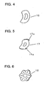
embodiment 2 is used as a nearly donut-like leaf spring, different elastic members shaped as illustrated in Figs. 4, 5, and 6 provide similar effects. - Fig. 4 is an enlarged perspective view of another leaf spring according to
embodiment 2. In Fig. 4,reference numeral 16 denotes a leaf spring having a curvilinear surface. Such a leaf spring shape allows for compressor assembly regardless of where the leaf spring is oriented. - Fig. 5 is an enlarged perspective view of a further leaf spring according to
embodiment 2. In Fig. 5,reference numeral 17 denotes a leaf spring having peripheral portions 17a bent toward the cylinder head. As a result, ends of theleaf spring 17 are held in linear contact with the cylinder, thereby isolating the cylinder head from scoring and wear. - Fig. 6 is an enlarged perspective view of a yet further leaf spring according to
embodiment 2. In Fig. 6,reference numeral 18 denotes a serrated leaf spring circumferentially bent in a sinusoidal manner. This configuration is possible to sufficiently ensure an area of contact between the cylinder head and the intake muffler. As a result, the cylinder head and intake muffler are isolated from scoring and wear. - As discussed above, the present invention comprises: a compression element placed in a hermetic vessel; a cylinder block including a cylinder that forms the compression element; a valve plate including an intake port, the valve plate being disposed on the cylinder at an opening end thereof; a cylinder head rigidly secured to the valve plate opposite to the cylinder; an intake muffler having an outlet positioned in the cylinder head at a concave thereof, and further having an orifice of the outlet provided at a distal end of the intake muffler and opened to the intake port; and a substantially disk-like elastic member disposed between the outlet and the cylinder head, wherein the outlet orifice of the intake muffler always remains pressed against the intake port. As a result, the intake muffler can elastically be fixed without being rattled. This feature makes it feasible to provide a low noise, low cost compressor with improved productivity.
- According to the present invention, the elastic member includes a substantially donut-like leaf spring loosely engaged with a protrusion that is provided on either a rear surface of the intake muffler at the outlet orifice of the intake muffler or an inner surface of the cylinder head at the concave of the cylinder head. This configuration makes it possible to provide further improved productivity, and thus provides a low cost compressor.
- According to the present invention, the leaf spring is provided with a curvilinear surface. This configuration causes both a bending center of the leaf spring and ends of the leaf spring to always remain pressed against either the rear surface of the intake muffler at the orifice end of the intake muffler toward the cylinder or the inner surface of the cylinder head at the concave of the cylinder head. Consequently, required spring characteristics are achievable in a stable manner, even with a small leaf spring. As a result, the leaf spring is usable on a small-sized compressor such as a refrigerator-dedicated compressor that is designed for use in a highly limited accommodation space.
- According to the present invention, the leaf spring has peripheral portions bent toward the cylinder head, and ends of the leaf spring are held in linear contact with the cylinder head. As a result, a longer life compressor having wear-resistant contact portions is available at low cost.
- According to the present invention, the substantially disk-like elastic means is a serrated leaf spring circumferentially bent in a sinusoidal fashion. As a result, a longer life compressor having wear-resistant contact portions is available, in which an area of contact between the cylinder head and the intake muffler can be increased while a sufficient elastic force is retained.
Claims (4)
- A hermetic compressor comprising:a hermetic vessel (1),a compression element placed in the hermetic vessel;a cylinder block including a cylinder (4) that forms the compression element;a valve plate (9) including an intake port, the valve plate being disposed on an opening end of the cylinder;a cylinder head (11) rigidly secured to the valve plate opposite to the cylinder;an intake muffler (6) having an outlet positioned in a concave of the cylinder head, and further having an orifice of the outlet provided at a distal end of the intake muffler and opened to the intake port; and an elastic member (10) disposed between the outlet and the cylinder head, said orifice of the outlet of the intake muffler constantly remaining pressed against the intake port, characterized in that the elastic member (10) is substantially disk-like and includes a substantially donut-like leaf spring loosely engaged with a protrusion that is provided on either one of a rear surface of the intake muffler at the outlet orifice thereof and an inner surface of the cylinder head at the concave thereof.
- A hermetic compressor as defined in claim 1, wherein the leaf spring has a curvilinear surface.
- A hermetic compressor as defined in claim 2, wherein the leaf spring has peripheral portions bent toward the cylinder head.
- A hermetic compressor as defined in claims 1 or 2, wherein the leaf spring is a waved leaf spring which is bent in a direction of the circumference thereof.
Applications Claiming Priority (3)
| Application Number | Priority Date | Filing Date | Title |
|---|---|---|---|
| JP2000391958 | 2000-12-25 | ||
| JP2000391958A JP3633865B2 (en) | 2000-12-25 | 2000-12-25 | Hermetic compressor |
| PCT/JP2001/011197 WO2002052152A1 (en) | 2000-12-25 | 2001-12-20 | Closed compressor |
Publications (3)
| Publication Number | Publication Date |
|---|---|
| EP1347174A1 EP1347174A1 (en) | 2003-09-24 |
| EP1347174A4 EP1347174A4 (en) | 2004-08-11 |
| EP1347174B1 true EP1347174B1 (en) | 2007-02-14 |
Family
ID=18858025
Family Applications (1)
| Application Number | Title | Priority Date | Filing Date |
|---|---|---|---|
| EP01271849A Expired - Lifetime EP1347174B1 (en) | 2000-12-25 | 2001-12-20 | Closed compressor |
Country Status (7)
| Country | Link |
|---|---|
| US (1) | US6957951B2 (en) |
| EP (1) | EP1347174B1 (en) |
| JP (1) | JP3633865B2 (en) |
| KR (1) | KR100553063B1 (en) |
| CN (1) | CN100549415C (en) |
| DE (1) | DE60126660T2 (en) |
| WO (1) | WO2002052152A1 (en) |
Families Citing this family (6)
| Publication number | Priority date | Publication date | Assignee | Title |
|---|---|---|---|---|
| KR100871130B1 (en) * | 2002-10-31 | 2008-12-03 | 엘지전자 주식회사 | Suction Muffler in Hermetic Compressor |
| JP6028211B2 (en) | 2011-10-12 | 2016-11-16 | パナソニックIpマネジメント株式会社 | Hermetic compressor and refrigeration apparatus provided with the same |
| WO2017061967A1 (en) | 2015-10-08 | 2017-04-13 | Arcelik Anonim Sirketi | A compressor with a suction muffler |
| TR201601561A2 (en) | 2016-02-05 | 2017-08-21 | Arcelik As | A COMPRESSOR WITH SUCTION SILENCER |
| WO2017153272A1 (en) | 2016-03-07 | 2017-09-14 | Arcelik Anonim Sirketi | A compressor with suction muffler |
| CN113357777A (en) * | 2021-05-31 | 2021-09-07 | 青岛海尔空调器有限总公司 | Method and device for identifying air conditioner state, air conditioner and air conditioning system |
Family Cites Families (11)
| Publication number | Priority date | Publication date | Assignee | Title |
|---|---|---|---|---|
| FR1430466A (en) | 1965-02-23 | 1966-03-04 | Licentia Gmbh | Cylinder head for refrigeration compressors |
| IT1184167B (en) * | 1985-03-21 | 1987-10-22 | Eurodomestici Ind Riunite | IMPROVEMENT IN SEALED MOTOR-COMPRESSORS FOR REFRIGERANT CIRCUITS |
| BR8602173A (en) | 1986-05-02 | 1987-12-22 | Brasil Compressores Sa | IMPROVEMENT IN A HERMETIC COOLING COMPRESSOR SUCTION SYSTEM |
| US5207564A (en) * | 1992-04-21 | 1993-05-04 | White Consolidated Industries, Inc. | Compressor head and suction muffler for hermetic compressor |
| IT1278603B1 (en) * | 1994-11-03 | 1997-11-24 | Necchi Compressori | HERMETIC MOTOR-COMPRESSOR |
| CN1247897C (en) * | 1995-04-20 | 2006-03-29 | Lg电子株式会社 | Sealed compressor |
| KR0156720B1 (en) * | 1995-07-27 | 1999-03-20 | 김광호 | Reciprocating compressor |
| KR0136621Y1 (en) * | 1995-10-31 | 1999-03-20 | 구자홍 | Suction muffler locking device of a hermetic electric compressor |
| IT241575Y1 (en) | 1996-11-19 | 2001-05-09 | Zanussi Elettromecc | REFRIGERATED COMPRESSOR WITH HEAD AND SILENCER PERFECTED |
| JP2000291547A (en) * | 1999-04-06 | 2000-10-17 | Matsushita Refrig Co Ltd | Hermetic electric compressor |
| DE19915918C2 (en) * | 1999-04-09 | 2001-05-31 | Danfoss Compressors Gmbh | Refrigerant compressor and method for its assembly |
-
2000
- 2000-12-25 JP JP2000391958A patent/JP3633865B2/en not_active Expired - Fee Related
-
2001
- 2001-12-20 KR KR1020037008219A patent/KR100553063B1/en not_active Expired - Fee Related
- 2001-12-20 WO PCT/JP2001/011197 patent/WO2002052152A1/en not_active Ceased
- 2001-12-20 US US10/433,670 patent/US6957951B2/en not_active Expired - Lifetime
- 2001-12-20 CN CNB018213189A patent/CN100549415C/en not_active Expired - Fee Related
- 2001-12-20 DE DE60126660T patent/DE60126660T2/en not_active Expired - Lifetime
- 2001-12-20 EP EP01271849A patent/EP1347174B1/en not_active Expired - Lifetime
Also Published As
| Publication number | Publication date |
|---|---|
| DE60126660T2 (en) | 2007-10-31 |
| EP1347174A4 (en) | 2004-08-11 |
| CN1483110A (en) | 2004-03-17 |
| US20040037712A1 (en) | 2004-02-26 |
| WO2002052152A1 (en) | 2002-07-04 |
| KR100553063B1 (en) | 2006-02-15 |
| DE60126660D1 (en) | 2007-03-29 |
| US6957951B2 (en) | 2005-10-25 |
| JP2002195158A (en) | 2002-07-10 |
| CN100549415C (en) | 2009-10-14 |
| EP1347174A1 (en) | 2003-09-24 |
| JP3633865B2 (en) | 2005-03-30 |
| KR20030063438A (en) | 2003-07-28 |
Similar Documents
| Publication | Publication Date | Title |
|---|---|---|
| US8230968B2 (en) | Suction muffler for hermetic compressor | |
| KR100422363B1 (en) | Valve assembly for compressor | |
| KR880000987B1 (en) | Compressor discharge valve | |
| US6957951B2 (en) | Closed compressor | |
| CN101321952A (en) | Closed compressor | |
| KR100714577B1 (en) | Discharge Valve Assembly of Linear Compressor | |
| JP2894995B2 (en) | Reciprocating compressor cylinder device | |
| KR100421965B1 (en) | Cylinder assembly of hermetic compressor | |
| US6932115B2 (en) | Valve apparatus for hermetic compressor | |
| KR100258420B1 (en) | Reciprocating compressor | |
| KR100273739B1 (en) | Valve device of hermetic compressor | |
| KR20020057628A (en) | Valve assembly for a reciprocating compressor | |
| JPH11311337A (en) | Oil seal | |
| JP2003097445A (en) | Linear compressor for co2 refrigerant | |
| KR100621045B1 (en) | Connecting rod of hermetic compressor | |
| KR200200259Y1 (en) | Valve device of hermetic compressor | |
| KR100548286B1 (en) | Reciprocating compressor | |
| KR100366456B1 (en) | A silencer for hermetic compressor | |
| KR100451219B1 (en) | Discharge valve structure for reciprocating compressor | |
| KR100241430B1 (en) | Cylinder head mounting structure of hermetic compressor | |
| KR100199969B1 (en) | Reciprocating compressors with valve leads | |
| KR20050117396A (en) | Discharge valve assembly for compressor | |
| KR20010084548A (en) | A valve device of compressor | |
| KR20040012217A (en) | Valve stopper for compressor | |
| KR20040105162A (en) | Discharge valve assembly |
Legal Events
| Date | Code | Title | Description |
|---|---|---|---|
| PUAI | Public reference made under article 153(3) epc to a published international application that has entered the european phase |
Free format text: ORIGINAL CODE: 0009012 |
|
| 17P | Request for examination filed |
Effective date: 20030617 |
|
| AK | Designated contracting states |
Kind code of ref document: A1 Designated state(s): DE ES FR GB IT |
|
| RIN1 | Information on inventor provided before grant (corrected) |
Inventor name: MOTEGI, MANABU Inventor name: OSAKA, MASAHIKO; Inventor name: OTA, TOSHIHIKO Inventor name: NOGUCHI, KAZUHITO Inventor name: KUBOTA, AKIHIKO Inventor name: KOJIMA, TAKESHI Inventor name: NISHIHARA, HIDETOSHI |
|
| RBV | Designated contracting states (corrected) |
Designated state(s): DE FR GB IT |
|
| A4 | Supplementary search report drawn up and despatched |
Effective date: 20040629 |
|
| GRAP | Despatch of communication of intention to grant a patent |
Free format text: ORIGINAL CODE: EPIDOSNIGR1 |
|
| GRAS | Grant fee paid |
Free format text: ORIGINAL CODE: EPIDOSNIGR3 |
|
| GRAA | (expected) grant |
Free format text: ORIGINAL CODE: 0009210 |
|
| AK | Designated contracting states |
Kind code of ref document: B1 Designated state(s): DE FR GB IT |
|
| REG | Reference to a national code |
Ref country code: GB Ref legal event code: FG4D |
|
| REF | Corresponds to: |
Ref document number: 60126660 Country of ref document: DE Date of ref document: 20070329 Kind code of ref document: P |
|
| EN | Fr: translation not filed | ||
| PLBE | No opposition filed within time limit |
Free format text: ORIGINAL CODE: 0009261 |
|
| STAA | Information on the status of an ep patent application or granted ep patent |
Free format text: STATUS: NO OPPOSITION FILED WITHIN TIME LIMIT |
|
| 26N | No opposition filed |
Effective date: 20071115 |
|
| PG25 | Lapsed in a contracting state [announced via postgrant information from national office to epo] |
Ref country code: FR Free format text: LAPSE BECAUSE OF FAILURE TO SUBMIT A TRANSLATION OF THE DESCRIPTION OR TO PAY THE FEE WITHIN THE PRESCRIBED TIME-LIMIT Effective date: 20071005 |
|
| GBPC | Gb: european patent ceased through non-payment of renewal fee |
Effective date: 20071220 |
|
| PG25 | Lapsed in a contracting state [announced via postgrant information from national office to epo] |
Ref country code: FR Free format text: LAPSE BECAUSE OF FAILURE TO SUBMIT A TRANSLATION OF THE DESCRIPTION OR TO PAY THE FEE WITHIN THE PRESCRIBED TIME-LIMIT Effective date: 20070214 |
|
| PG25 | Lapsed in a contracting state [announced via postgrant information from national office to epo] |
Ref country code: GB Free format text: LAPSE BECAUSE OF NON-PAYMENT OF DUE FEES Effective date: 20071220 |
|
| PGFP | Annual fee paid to national office [announced via postgrant information from national office to epo] |
Ref country code: IT Payment date: 20131211 Year of fee payment: 13 |
|
| PG25 | Lapsed in a contracting state [announced via postgrant information from national office to epo] |
Ref country code: IT Free format text: LAPSE BECAUSE OF NON-PAYMENT OF DUE FEES Effective date: 20141220 |
|
| PGFP | Annual fee paid to national office [announced via postgrant information from national office to epo] |
Ref country code: DE Payment date: 20171211 Year of fee payment: 17 |
|
| REG | Reference to a national code |
Ref country code: DE Ref legal event code: R081 Ref document number: 60126660 Country of ref document: DE Owner name: PANASONIC APPLIANCES REFRIGERATION DEVICES SIN, SG Free format text: FORMER OWNER: PANASONIC CORPORATION, KADOMA-SHI, OSAKA, JP |
|
| REG | Reference to a national code |
Ref country code: DE Ref legal event code: R119 Ref document number: 60126660 Country of ref document: DE |
|
| PG25 | Lapsed in a contracting state [announced via postgrant information from national office to epo] |
Ref country code: DE Free format text: LAPSE BECAUSE OF NON-PAYMENT OF DUE FEES Effective date: 20190702 |