EP1346961A1 - Recoating method and recoating apparatus for optical fiber - Google Patents
Recoating method and recoating apparatus for optical fiber Download PDFInfo
- Publication number
- EP1346961A1 EP1346961A1 EP03005716A EP03005716A EP1346961A1 EP 1346961 A1 EP1346961 A1 EP 1346961A1 EP 03005716 A EP03005716 A EP 03005716A EP 03005716 A EP03005716 A EP 03005716A EP 1346961 A1 EP1346961 A1 EP 1346961A1
- Authority
- EP
- European Patent Office
- Prior art keywords
- recoating
- resin
- optical fiber
- mold
- mold forms
- Prior art date
- Legal status (The legal status is an assumption and is not a legal conclusion. Google has not performed a legal analysis and makes no representation as to the accuracy of the status listed.)
- Withdrawn
Links
- 239000013307 optical fiber Substances 0.000 title claims abstract description 49
- 238000000034 method Methods 0.000 title claims abstract description 31
- 239000011347 resin Substances 0.000 claims abstract description 140
- 229920005989 resin Polymers 0.000 claims abstract description 140
- 238000002347 injection Methods 0.000 claims abstract description 74
- 239000007924 injection Substances 0.000 claims abstract description 74
- 239000000835 fiber Substances 0.000 claims abstract description 26
- VYPSYNLAJGMNEJ-UHFFFAOYSA-N Silicium dioxide Chemical compound O=[Si]=O VYPSYNLAJGMNEJ-UHFFFAOYSA-N 0.000 claims description 5
- 230000001678 irradiating effect Effects 0.000 claims description 5
- 238000010348 incorporation Methods 0.000 abstract description 8
- 238000001723 curing Methods 0.000 description 19
- 230000000284 resting effect Effects 0.000 description 6
- 230000000052 comparative effect Effects 0.000 description 5
- 230000036961 partial effect Effects 0.000 description 5
- 239000011248 coating agent Substances 0.000 description 3
- 238000000576 coating method Methods 0.000 description 3
- 230000006866 deterioration Effects 0.000 description 2
- 238000007526 fusion splicing Methods 0.000 description 2
- 239000011521 glass Substances 0.000 description 2
- 238000003780 insertion Methods 0.000 description 2
- 230000037431 insertion Effects 0.000 description 2
- 230000000670 limiting effect Effects 0.000 description 2
- 230000014759 maintenance of location Effects 0.000 description 2
- 230000003287 optical effect Effects 0.000 description 2
- 230000002829 reductive effect Effects 0.000 description 2
- 230000000717 retained effect Effects 0.000 description 2
- AFCARXCZXQIEQB-UHFFFAOYSA-N N-[3-oxo-3-(2,4,6,7-tetrahydrotriazolo[4,5-c]pyridin-5-yl)propyl]-2-[[3-(trifluoromethoxy)phenyl]methylamino]pyrimidine-5-carboxamide Chemical compound O=C(CCNC(=O)C=1C=NC(=NC=1)NCC1=CC(=CC=C1)OC(F)(F)F)N1CC2=C(CC1)NN=N2 AFCARXCZXQIEQB-UHFFFAOYSA-N 0.000 description 1
- 238000003848 UV Light-Curing Methods 0.000 description 1
- JAWMENYCRQKKJY-UHFFFAOYSA-N [3-(2,4,6,7-tetrahydrotriazolo[4,5-c]pyridin-5-ylmethyl)-1-oxa-2,8-diazaspiro[4.5]dec-2-en-8-yl]-[2-[[3-(trifluoromethoxy)phenyl]methylamino]pyrimidin-5-yl]methanone Chemical compound N1N=NC=2CN(CCC=21)CC1=NOC2(C1)CCN(CC2)C(=O)C=1C=NC(=NC=1)NCC1=CC(=CC=C1)OC(F)(F)F JAWMENYCRQKKJY-UHFFFAOYSA-N 0.000 description 1
- 230000005540 biological transmission Effects 0.000 description 1
- 230000000694 effects Effects 0.000 description 1
- 238000011835 investigation Methods 0.000 description 1
- 239000000463 material Substances 0.000 description 1
- 230000001105 regulatory effect Effects 0.000 description 1
Images




Classifications
-
- G—PHYSICS
- G02—OPTICS
- G02B—OPTICAL ELEMENTS, SYSTEMS OR APPARATUS
- G02B6/00—Light guides; Structural details of arrangements comprising light guides and other optical elements, e.g. couplings
- G02B6/24—Coupling light guides
- G02B6/255—Splicing of light guides, e.g. by fusion or bonding
- G02B6/2558—Reinforcement of splice joint
-
- B—PERFORMING OPERATIONS; TRANSPORTING
- B29—WORKING OF PLASTICS; WORKING OF SUBSTANCES IN A PLASTIC STATE IN GENERAL
- B29C—SHAPING OR JOINING OF PLASTICS; SHAPING OF MATERIAL IN A PLASTIC STATE, NOT OTHERWISE PROVIDED FOR; AFTER-TREATMENT OF THE SHAPED PRODUCTS, e.g. REPAIRING
- B29C45/00—Injection moulding, i.e. forcing the required volume of moulding material through a nozzle into a closed mould; Apparatus therefor
- B29C45/0053—Injection moulding, i.e. forcing the required volume of moulding material through a nozzle into a closed mould; Apparatus therefor combined with a final operation, e.g. shaping
-
- B—PERFORMING OPERATIONS; TRANSPORTING
- B29—WORKING OF PLASTICS; WORKING OF SUBSTANCES IN A PLASTIC STATE IN GENERAL
- B29C—SHAPING OR JOINING OF PLASTICS; SHAPING OF MATERIAL IN A PLASTIC STATE, NOT OTHERWISE PROVIDED FOR; AFTER-TREATMENT OF THE SHAPED PRODUCTS, e.g. REPAIRING
- B29C45/00—Injection moulding, i.e. forcing the required volume of moulding material through a nozzle into a closed mould; Apparatus therefor
- B29C45/14—Injection moulding, i.e. forcing the required volume of moulding material through a nozzle into a closed mould; Apparatus therefor incorporating preformed parts or layers, e.g. injection moulding around inserts or for coating articles
- B29C45/14336—Coating a portion of the article, e.g. the edge of the article
- B29C45/14434—Coating brittle material, e.g. glass
-
- B—PERFORMING OPERATIONS; TRANSPORTING
- B29—WORKING OF PLASTICS; WORKING OF SUBSTANCES IN A PLASTIC STATE IN GENERAL
- B29C—SHAPING OR JOINING OF PLASTICS; SHAPING OF MATERIAL IN A PLASTIC STATE, NOT OTHERWISE PROVIDED FOR; AFTER-TREATMENT OF THE SHAPED PRODUCTS, e.g. REPAIRING
- B29C45/00—Injection moulding, i.e. forcing the required volume of moulding material through a nozzle into a closed mould; Apparatus therefor
- B29C45/14—Injection moulding, i.e. forcing the required volume of moulding material through a nozzle into a closed mould; Apparatus therefor incorporating preformed parts or layers, e.g. injection moulding around inserts or for coating articles
- B29C45/14549—Coating rod-like, wire-like or belt-like articles
-
- B—PERFORMING OPERATIONS; TRANSPORTING
- B29—WORKING OF PLASTICS; WORKING OF SUBSTANCES IN A PLASTIC STATE IN GENERAL
- B29D—PRODUCING PARTICULAR ARTICLES FROM PLASTICS OR FROM SUBSTANCES IN A PLASTIC STATE
- B29D11/00—Producing optical elements, e.g. lenses or prisms
- B29D11/00663—Production of light guides
-
- B—PERFORMING OPERATIONS; TRANSPORTING
- B29—WORKING OF PLASTICS; WORKING OF SUBSTANCES IN A PLASTIC STATE IN GENERAL
- B29D—PRODUCING PARTICULAR ARTICLES FROM PLASTICS OR FROM SUBSTANCES IN A PLASTIC STATE
- B29D11/00—Producing optical elements, e.g. lenses or prisms
- B29D11/00865—Applying coatings; tinting; colouring
- B29D11/00875—Applying coatings; tinting; colouring on light guides
-
- C—CHEMISTRY; METALLURGY
- C03—GLASS; MINERAL OR SLAG WOOL
- C03C—CHEMICAL COMPOSITION OF GLASSES, GLAZES OR VITREOUS ENAMELS; SURFACE TREATMENT OF GLASS; SURFACE TREATMENT OF FIBRES OR FILAMENTS MADE FROM GLASS, MINERALS OR SLAGS; JOINING GLASS TO GLASS OR OTHER MATERIALS
- C03C25/00—Surface treatment of fibres or filaments made from glass, minerals or slags
- C03C25/10—Coating
- C03C25/12—General methods of coating; Devices therefor
-
- C—CHEMISTRY; METALLURGY
- C03—GLASS; MINERAL OR SLAG WOOL
- C03C—CHEMICAL COMPOSITION OF GLASSES, GLAZES OR VITREOUS ENAMELS; SURFACE TREATMENT OF GLASS; SURFACE TREATMENT OF FIBRES OR FILAMENTS MADE FROM GLASS, MINERALS OR SLAGS; JOINING GLASS TO GLASS OR OTHER MATERIALS
- C03C25/00—Surface treatment of fibres or filaments made from glass, minerals or slags
- C03C25/10—Coating
- C03C25/12—General methods of coating; Devices therefor
- C03C25/18—Extrusion
-
- G—PHYSICS
- G02—OPTICS
- G02B—OPTICAL ELEMENTS, SYSTEMS OR APPARATUS
- G02B6/00—Light guides; Structural details of arrangements comprising light guides and other optical elements, e.g. couplings
- G02B6/24—Coupling light guides
- G02B6/255—Splicing of light guides, e.g. by fusion or bonding
- G02B6/2551—Splicing of light guides, e.g. by fusion or bonding using thermal methods, e.g. fusion welding by arc discharge, laser beam, plasma torch
-
- B—PERFORMING OPERATIONS; TRANSPORTING
- B29—WORKING OF PLASTICS; WORKING OF SUBSTANCES IN A PLASTIC STATE IN GENERAL
- B29C—SHAPING OR JOINING OF PLASTICS; SHAPING OF MATERIAL IN A PLASTIC STATE, NOT OTHERWISE PROVIDED FOR; AFTER-TREATMENT OF THE SHAPED PRODUCTS, e.g. REPAIRING
- B29C33/00—Moulds or cores; Details thereof or accessories therefor
- B29C2033/0005—Moulds or cores; Details thereof or accessories therefor with transparent parts, e.g. permitting visual inspection of the interior of the cavity
-
- B—PERFORMING OPERATIONS; TRANSPORTING
- B29—WORKING OF PLASTICS; WORKING OF SUBSTANCES IN A PLASTIC STATE IN GENERAL
- B29C—SHAPING OR JOINING OF PLASTICS; SHAPING OF MATERIAL IN A PLASTIC STATE, NOT OTHERWISE PROVIDED FOR; AFTER-TREATMENT OF THE SHAPED PRODUCTS, e.g. REPAIRING
- B29C45/00—Injection moulding, i.e. forcing the required volume of moulding material through a nozzle into a closed mould; Apparatus therefor
- B29C45/0053—Injection moulding, i.e. forcing the required volume of moulding material through a nozzle into a closed mould; Apparatus therefor combined with a final operation, e.g. shaping
- B29C2045/0075—Injection moulding, i.e. forcing the required volume of moulding material through a nozzle into a closed mould; Apparatus therefor combined with a final operation, e.g. shaping curing or polymerising by irradiation
-
- B—PERFORMING OPERATIONS; TRANSPORTING
- B29—WORKING OF PLASTICS; WORKING OF SUBSTANCES IN A PLASTIC STATE IN GENERAL
- B29C—SHAPING OR JOINING OF PLASTICS; SHAPING OF MATERIAL IN A PLASTIC STATE, NOT OTHERWISE PROVIDED FOR; AFTER-TREATMENT OF THE SHAPED PRODUCTS, e.g. REPAIRING
- B29C45/00—Injection moulding, i.e. forcing the required volume of moulding material through a nozzle into a closed mould; Apparatus therefor
- B29C45/03—Injection moulding apparatus
- B29C45/04—Injection moulding apparatus using movable moulds or mould halves
- B29C45/0408—Injection moulding apparatus using movable moulds or mould halves involving at least a linear movement
- B29C45/0416—Injection moulding apparatus using movable moulds or mould halves involving at least a linear movement co-operating with fixed mould halves
- B29C2045/0425—Book moulds, i.e. a mould half can be opened and closed like a book with regard to the other mould half, the mould halves being connected by a hinge
-
- B—PERFORMING OPERATIONS; TRANSPORTING
- B29—WORKING OF PLASTICS; WORKING OF SUBSTANCES IN A PLASTIC STATE IN GENERAL
- B29C—SHAPING OR JOINING OF PLASTICS; SHAPING OF MATERIAL IN A PLASTIC STATE, NOT OTHERWISE PROVIDED FOR; AFTER-TREATMENT OF THE SHAPED PRODUCTS, e.g. REPAIRING
- B29C45/00—Injection moulding, i.e. forcing the required volume of moulding material through a nozzle into a closed mould; Apparatus therefor
- B29C45/17—Component parts, details or accessories; Auxiliary operations
- B29C45/76—Measuring, controlling or regulating
- B29C45/77—Measuring, controlling or regulating of velocity or pressure of moulding material
-
- B—PERFORMING OPERATIONS; TRANSPORTING
- B29—WORKING OF PLASTICS; WORKING OF SUBSTANCES IN A PLASTIC STATE IN GENERAL
- B29L—INDEXING SCHEME ASSOCIATED WITH SUBCLASS B29C, RELATING TO PARTICULAR ARTICLES
- B29L2011/00—Optical elements, e.g. lenses, prisms
- B29L2011/0075—Light guides, optical cables
Definitions
- the present invention relates to a recoating method for optical fiber wherein a resin sheath is recoated onto a part where the sheath of the optical fibber has been removed, and a recoating apparatus for the same, and in particular, relates to limiting the immixture of bubbles into a recoating resin and limiting the deterioration of the outward appearance and shape of the recoated part.
- a portion of the fiber in which the coating was removed (a bare fiber portion) must be coated with resin again for the sake of protection. That is, it must be recoated.
- FIG. 2 and FIG. 3 is a method using a recoating apparatus.
- recoating of the fiber is carried out by injecting a recoating resin into a glass mold (the mold method).
- This recoating apparatus 10 comprises a pair of plate shaped mold forms (the forms which are made of a glass material such as silica glass which is normally transparent and has superior light transparency) 11A, 11B which are divided into an upper part and a lower part. These mold forms 11A, 11B are disposed between a base stand 12 and a lid 13 which is installed in the base stand 12 so that it can be opened and closed.
- the recoating resin normally a UV cured resin
- U groove semicircular mold grooves
- the length of each of the mold grooves 17 is set, for example, so as to be longer than the portion of a bare fiber portion 1a of the optical fiber that was spliced by heat fusion splicing.
- a resin curing device 18 such as a UV lamp
- the curing of the resin is promoted by irradiating the UV light, and thus a quick mold becomes possible.
- the present inventors carried out investigations of the conditions such as immixture of the bubbles and deformation of the shape, and obtained the following conclusions.
- the injection speed exceeds 6 mm/second, it is discovered that the generation of bubbles a 1 is conspicuous.
- an object of the present invention is to provide a recoating method for optical fiber wherein the incorporation of bubbles into the resin and the deterioration of external shape of the resin can be maximally suppressed principally by regulating the injection speed of the recoating resin and the irradiation timing of the curing light on the resin, and a recoating apparatus that can implement this method.
- a first aspect of the present invention is a recoating method for optical fiber in which recoating of a bare fiber portion of an optical fiber is carried out by guiding a recoating resin into two molds forms, wherein the injection speed of the recoating resin injected into mold grooves in the mold forms is set as a speed at which bubbles are not trapped due to the resin injection.
- the above injection speed is equal to or less than 6 mm/second.
- a second aspect of the present invention is a recoating method for optical fiber in which recoating of a bare fiber portion of an optical fiber is carried out by guiding a recoating resin into two molds forms, wherein the injection speed of the recoating resin that is injected into the mold grooves of the mold forms is reduced to equal to or less than 6 mm/second while the recoating resin is injected in proximity to a position corresponding to a tip of a recoated sheath which is made of the recoating resin.
- a third aspect of the present invention is a recoating method for optical fiber in which recoating of a bare fiber portion of an optical fiber is carried out by guiding a recoating resin into two mold forms, wherein curing light is irradiated from a resin curing device after passage of an appropriate time interval following completion of the injection of the recoating resin into the mold grooves of the mold forms.
- the above time interval is equal to or greater than 2 seconds.
- a fourth aspect of the present invention is a recoating apparatus that implements the recoating method described above.
- the recoating apparatus comprises a plate-shaped optically transparent mold divided into upper and lower mold forms. Semicircular mold grooves are provided on the abutment face side of the upper and lower mold forms, and a slit-shaped resin guide path that leads to the mold grooves is provided on the abutment face side of one of the mold forms. Furthermore, a resin injection path comprising a small hole that communicates with the slit shaped resin guide path is provided on one of the mold forms, and a resin curing device that irradiates UV light is provided on a side of one of the mold forms.
- a recoating of an optical fiber is performed by the following steps; installing the optical fiber having a bare fiber portion whose length is shorter that that of the mold grooves between the semicircular mold grooves, injecting a recoating resin around the bare fiber portion through the resin injection path and the resin guide path, and irradiating a UV light by the resin curing device.
- the recoating apparatus is characterized by implementing the recoating method which is described in the above first, second, or third aspects.
- the plate-shaped optically transparent mold is made of silica glass.
- the upper and lower mold forms are disposed between a base stand and a lid installed thereon and can be opened and closed, and a resin injection path comprising a small hole which communicates with the resin injection path of the mold forms is provided on either the base stand or the lid.
- the recoating method for optical fiber according to the present invention is not particularly limited. However, for example, can be implemented by the recoating apparatus 10 as shown in the above described FIGS. 2 and 3.
- step S1 the object optical fiber 1 is set in the mold grooves 17 of the mold forms 11A, 11B of the recoating apparatus 10. Thereby, a substantially closed cylindrical mold space is formed around the bare fiber portion 1 a of the optical fiber 1 by the mold grooves 17.
- step S2 a recoating resin is injected into the mold space between the mold grooves 17 through the resin injection paths 14, 15 of the base stand 12 and the lower mold form 11A, and the resin guide path 16 of the upper mold form 11B.
- the injection speed of the recoating resin is equal to or less than 6 mm/second. This speed is maintained until a set injection amount of the recoating resin is attained depending on the volume of the mold space.
- the injection speed of the resin is usually carried out at about 8 to 10 mm/second.
- the injection speed in proximity to the discharge opening of the resin guide path 16 is equal to or less than 6 mm/second, the injection speed in proximity to the end of the recoating sheath 2 which is positioned relatively apart from the discharge opening is smaller than the injection speed in proximity to the discharge opening, and thus no impediment is caused by the difference of the injection speed in the mold forms 11A, 11B.
- step S3 an optical fiber 1 having a predetermined recoating sheath 2 over the bare fiber portion 1 a is obtained.
- the above time interval (resting time) is equal to or greater than 2. That is, if UV light is irradiated following the passage of 2 seconds or more after the resin injection is stopped, at nearly all parts of the injection recoating resin, for example, the part (in proximity to the resin guide path 16) shown in FIG. 7, the flow of the resin is almost completely stopped, and thus the curing of the resin can be carried out evenly, and a well shaped recoating sheath 2 is obtained that has any deformations of the shape of the external appearance effectively suppressed.
- the reason that the time interval is 2 seconds or greater is that when the time interval is approximately 2 seconds, the flow of the recoating resin is stopped in almost all parts.
- a recoating sheath for an optical fiber is formed with an injection speed for the recoating resin that satisfies the conditions of the present invention or with an injection speed for the recoating resin that fails to satisfy the conditions of the present invention.
- the state of incorporation of the bubbles a 1 in the resin guide path 16 of the mold form 11B shown in FIG. 5 and the bubbles a 2 in proximity to the end of the recoating sheath 2 shown in FIG. 6 are shown in Table 1.
- the inner diameter of the resin injection path 15 of the lower mold form 11 A was about 1 mm
- the width of the resin guide path 16 in the mold form 11B was about 4 mm
- the height thereof was 0.05 mm
- the recoating resin that was used was a UV cured resin
- the injection temperature was 20° C.
- Injection speed (mm/second) Presence or absence of bubbles (a 1 ) Presence or absence of bubbles (a 2 )
- a recoating sheath for an optical fiber was formed by irradiating UV light after passage of a resting time that satisfied the conditions of the present invention or a resting time that failed to satisfy the conditions of the present invention.
- the external appearance and shape of the deformation of the recoating sheath is shown in Table 2.
- the inner diameter of the resin injection path 15 of the lower mold form 11A was about 1 mm
- the width of the resin guide path 16 in the mold form 11B was about 4 mm
- the height thereof was 0.05 mm
- the recoating resin that was used was a UV curing resin
- the injection temperature was 20° C.
- a recoating apparatus having the following structures can be used for the present invention.
- This recoating apparatus comprises transparent plate-shaped mold divided into upper and lower mold forms 11A, 11B, and provides the semicircular mold grooves 17 on the abutting faces of the upper and lower mold forms 11A, 11B and provides a slit-shaped resin guide path 16 that connects to the mold grooves 17 on one of the abutting faces of the mold forms 11A and 11B.
- a resin injection path 15 comprising a small hole which communicates with the slit-shaped resin guide path 16 is provided on either one of the mold forms 11A, 11B, and a resin curing device 18 that irradiates UV light is provided on a side of either one of the mold forms 11A, 11B.
- an optical fiber 1 having a bare fiber portion 1a whose length is shorter than that of the mold grooves 17 is inserted between the semicircular mold grooves 17.
- the recoating resin is injected around the bare fiber portion 1 a of the optical fiber through the resin injection path 15 and the resin guide path 16, and irradiated by the resin curing device 18.
- a recoating sheath 2 that is, a molded part, is formed because a substantially closed semicircular mold space is formed around the bare fiber portion 1a due to the injection of the recoating resin.
- the injection speed of the recoating resin is such that bubbles to not become trapped due to the resin injection, that is, a speed equal to or less than 6 mm/second, and the injection speed in proximity to the end of the recoating sheath of the recoating resin injected into the mold grooves 17 is equal to or less than 6 mm/second.
- the transparent plate-shaped mold is made of silica glass, the insertion state of the optical fiber 1 and the bare fiber portion 1a can be visually inspected from the outside.
- the recoating operation can be carried out easily and quickly by opening and closing the lid 13.
- an observation window 13a for viewing the mold form 11B is provided on the lid 13, even when the lid is not transparent, it is possible to visually inspect the optical fiber 1 on the mold forms 11A, 11B side from the outside using the observation window 13a.
- the recoating apparatus that injects recoating resin into a mold groove can be broadly implemented by other apparatuses.
- the setting position of the resin curing device 18 such as a UV lamp is not limited to the recoating apparatus 10 described above.
Landscapes
- Engineering & Computer Science (AREA)
- Physics & Mathematics (AREA)
- Manufacturing & Machinery (AREA)
- Mechanical Engineering (AREA)
- Chemical & Material Sciences (AREA)
- Life Sciences & Earth Sciences (AREA)
- Plasma & Fusion (AREA)
- Organic Chemistry (AREA)
- Chemical Kinetics & Catalysis (AREA)
- General Chemical & Material Sciences (AREA)
- Geochemistry & Mineralogy (AREA)
- Materials Engineering (AREA)
- General Life Sciences & Earth Sciences (AREA)
- General Physics & Mathematics (AREA)
- Optics & Photonics (AREA)
- Ophthalmology & Optometry (AREA)
- Health & Medical Sciences (AREA)
- Mechanical Coupling Of Light Guides (AREA)
- Optical Fibers, Optical Fiber Cores, And Optical Fiber Bundles (AREA)
Abstract
The invention relates to a recoating method for optical fiber, and in particular to
prevent incorporation of bubbles into the recoating resin. In a recoating method for
optical fiber, a bare fiber portion of an optical fiber is recoated by guiding recoating
resin into mold forms (11A, 11B), and the injection speed of the recoating resin injected
into the mold forms is such that bubbles are not trapped due to the resin injection. This
injection speed is preferably equal to or less than 6 mm/second.
Description
- The present invention relates to a recoating method for optical fiber wherein a resin sheath is recoated onto a part where the sheath of the optical fibber has been removed, and a recoating apparatus for the same, and in particular, relates to limiting the immixture of bubbles into a recoating resin and limiting the deterioration of the outward appearance and shape of the recoated part.
- After connecting optical fibers by fusion splicing or after removing a coating from a portion that needs to have it removed, a portion of the fiber in which the coating was removed (a bare fiber portion) must be coated with resin again for the sake of protection. That is, it must be recoated.
- Several methods have already been proposed as recoating methods. The example shown in FIG. 2 and FIG. 3 is a method using a recoating apparatus. In this method, recoating of the fiber is carried out by injecting a recoating resin into a glass mold (the mold method).
- This recoating
apparatus 10 comprises a pair of plate shaped mold forms (the forms which are made of a glass material such as silica glass which is normally transparent and has superior light transparency) 11A, 11B which are divided into an upper part and a lower part. These mold forms 11A, 11B are disposed between abase stand 12 and alid 13 which is installed in thebase stand 12 so that it can be opened and closed. In addition, the recoating resin (normally a UV cured resin) is injected into semicircular mold grooves (U groove) 17 in themold forms resin injection paths base stand 12 and thelower mold form 11A, and a shallow slit-shapedresin guide path 16 is formed in theupper mold form 11B. - As shown in FIG. 4, the length of each of the
mold grooves 17 is set, for example, so as to be longer than the portion of abare fiber portion 1a of the optical fiber that was spliced by heat fusion splicing. - Therefore, when this
optical fiber 1 is set in each of themold grooves 17 of the mold forms 11A, 11B, a substantially closed cylindrical space (mold space) is formed around thebare fiber portion 1 a. Then, a recoatingsheath 2, that is, a molded part, is formed by injecting the above described recoating into the mold space. - Here, when a
resin curing device 18 such as a UV lamp is disposed on thebase stand 12 side, for example, the curing of the resin is promoted by irradiating the UV light, and thus a quick mold becomes possible. - However, in this recoating method using such recoating
apparatus 10, during the injection of the recoating resin, there is the case that bubbles are trapped into the resin or the resin is hardened by the irradiation of UV light while it is flowing, depending on the injection speed; and as a result, the problem that the shape of the resin of the recoated portion is deteriorated may occur. Of course, when bubbles are trapped or the shape is deformed, the optical transmission properties of theoptical fiber 1 become inferior. - The present inventors carried out investigations of the conditions such as immixture of the bubbles and deformation of the shape, and obtained the following conclusions. First, when the injection speed of the recoating resin is too fast, as shown in FIG. 5, it was discovered that a turbulent flow of the resin occurs in proximity to the
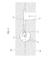
resin guide path 16 which forms a narrow path portion of themold form 11B, and in particular, in proximity to the discharge opening to themold grooves 17, and that bubbles a1 are easily trapped in the resin. In particular, when the injection speed exceeds 6 mm/second, it is discovered that the generation of bubbles a1 is conspicuous. - In addition, as shown in FIG. 6, when the injection speed of the recoating resin flowing into the mold space in the
mold grooves 17 is too fast, it was discovered that the discharge of residual air in the mold space is not carried out smoothly when the resin arrives at the tip portion of the recoatedsheath 2, and the bubbles a2 would be easily retained at the end face offiber coating parts 1b of theoptical fiber 1, that is, in proximity to the tip portion of the recoatedsheath 2. In this case, when the injection speed exceeded 6 mm/second, it is understood that the retention of bubbles a2 is conspicuous as well as the case described above. - Furthermore, conventionally, the curing of the resin is immediately carried out after completion of the recoating resin injection by irradiating UV light. However, in this case, the outward shape of the recoated resin is deteriorated. After researching the cause of this phenomenon, it was discovered that even if the injection was stopped, the flow did not immediately stop, but rather a part of the resin continued to flow slightly. This phenomenon could be frequently observed in proximity to the discharge opening of the
resin guide path 16 which forms a narrow path as shown in FIG. 7, for example. - Thus, when the recoating resin in a portion still flowing is irradiated with UV light, the curing of the resin in this flowing portion occurs with difficulty, and appears as a distortion in the shape. After researching this point in more detail, it was discovered that when UV light is irradiated after the passage of a certain time interval after the completion of the injection of the recoating resin, more preferably after the passage of 2 seconds, the deformation of the shape can be effectively prevented.
- In consideration of the above, an object of the present invention is to provide a recoating method for optical fiber wherein the incorporation of bubbles into the resin and the deterioration of external shape of the resin can be maximally suppressed principally by regulating the injection speed of the recoating resin and the irradiation timing of the curing light on the resin, and a recoating apparatus that can implement this method.
- A first aspect of the present invention is a recoating method for optical fiber in which recoating of a bare fiber portion of an optical fiber is carried out by guiding a recoating resin into two molds forms, wherein the injection speed of the recoating resin injected into mold grooves in the mold forms is set as a speed at which bubbles are not trapped due to the resin injection.
- In this recoating method for optical fiber, it is preferable that the above injection speed is equal to or less than 6 mm/second.
- A second aspect of the present invention is a recoating method for optical fiber in which recoating of a bare fiber portion of an optical fiber is carried out by guiding a recoating resin into two molds forms, wherein the injection speed of the recoating resin that is injected into the mold grooves of the mold forms is reduced to equal to or less than 6 mm/second while the recoating resin is injected in proximity to a position corresponding to a tip of a recoated sheath which is made of the recoating resin.
- A third aspect of the present invention is a recoating method for optical fiber in which recoating of a bare fiber portion of an optical fiber is carried out by guiding a recoating resin into two mold forms, wherein curing light is irradiated from a resin curing device after passage of an appropriate time interval following completion of the injection of the recoating resin into the mold grooves of the mold forms.
- In this recoating method for optical fiber, it is preferable that the above time interval is equal to or greater than 2 seconds.
- A fourth aspect of the present invention is a recoating apparatus that implements the recoating method described above. The recoating apparatus comprises a plate-shaped optically transparent mold divided into upper and lower mold forms. Semicircular mold grooves are provided on the abutment face side of the upper and lower mold forms, and a slit-shaped resin guide path that leads to the mold grooves is provided on the abutment face side of one of the mold forms. Furthermore, a resin injection path comprising a small hole that communicates with the slit shaped resin guide path is provided on one of the mold forms, and a resin curing device that irradiates UV light is provided on a side of one of the mold forms. In this apparatus, a recoating of an optical fiber is performed by the following steps; installing the optical fiber having a bare fiber portion whose length is shorter that that of the mold grooves between the semicircular mold grooves, injecting a recoating resin around the bare fiber portion through the resin injection path and the resin guide path, and irradiating a UV light by the resin curing device. Furthermore, the recoating apparatus is characterized by implementing the recoating method which is described in the above first, second, or third aspects.
- In this recoating apparatus, it is preferable that the plate-shaped optically transparent mold is made of silica glass.
- Furthermore, in the recoating apparatus as described above, it is preferable that the upper and lower mold forms are disposed between a base stand and a lid installed thereon and can be opened and closed, and a resin injection path comprising a small hole which communicates with the resin injection path of the mold forms is provided on either the base stand or the lid.
-
- FIG. 1 is a flow chart which showing an example of the recoating method for optical fiber according to the present invention.
- FIG. 2 is a partial cross-sectional view of the recoating apparatus for optical fiber.
- FIG. 3 is a partial cross-sectional view of the state wherein the lid in the recoating apparatus of FIG. 2 is open.
- FIG. 4 is an exploded perspective drawing which showing the relationship between the mold forms and the bare fiber portion of the optical fiber in the recoating apparatus of FIG. 2.
- FIG. 5 is a partial enlarged drawing of the recoating apparatus of FIG. 2 which showing the injection condition of a recoating resin in proximity to a resin guide path of mold forms.
- FIG. 6 is a partial enlarged drawing of the recoating apparatus of FIG. 2 which showing the injection condition of the recoating resin in a position corresponding to a tip of a recoated sheath which is made of the recoating resin.
- FIG. 7 is a partial enlarged drawing of the recoating apparatus of FIG. 2 which showing the injection condition of the recoating resin in proximity to the resin guide path of the mold forms.
-
- The recoating method for optical fiber according to the present invention is not particularly limited. However, for example, can be implemented by the recoating
apparatus 10 as shown in the above described FIGS. 2 and 3. - The procedure will be described with FIG. 1. First, in the present invention, in step S1, the object
optical fiber 1 is set in themold grooves 17 of the mold forms 11A, 11B of the recoatingapparatus 10. Thereby, a substantially closed cylindrical mold space is formed around thebare fiber portion 1 a of theoptical fiber 1 by themold grooves 17. - Next, in step S2, a recoating resin is injected into the mold space between the
mold grooves 17 through theresin injection paths base stand 12 and thelower mold form 11A, and theresin guide path 16 of theupper mold form 11B. - At this time, the injection speed of the recoating resin is equal to or less than 6 mm/second. This speed is maintained until a set injection amount of the recoating resin is attained depending on the volume of the mold space.
- Meanwhile, in the conventional recoating method, the injection speed of the resin is usually carried out at about 8 to 10 mm/second.
- By carrying out the injection as such a slow injection speed, in the portion shown in FIGS. 5 and 6 (the portion at the proximity of the discharge opening of the
resin guide path 16 in themold form 11B and the end face edge of thefiber covering parts 1b of theoptical fiber 1, that is, in proximity to the tip portion of the recoated sheath 2), the incorporation of bubbles a1 and a2 are efficiently limited. The reason is thought to be that; first, because the injection sped is slow, the generation of significant turbulence in proximity to the discharge opening of theresin guide path 16 is suppressed, and thus little air is trapped, and the retention of bubbles a1 can be suppressed. In addition, in proximity to the end of the recoatingsheath 2, it is thought that a clearance is created in which the air retained as bubbles a2 can escape from between the abutting faces of the mold forms 11A, 11B and from the gap between themold grooves 17 and thefiber covering part 1b of theoptical fiber 1 because the injection sped is slow. Moreover, in the case that the injection speed in proximity to the discharge opening of theresin guide path 16 is equal to or less than 6 mm/second, the injection speed in proximity to the end of the recoatingsheath 2 which is positioned relatively apart from the discharge opening is smaller than the injection speed in proximity to the discharge opening, and thus no impediment is caused by the difference of the injection speed in the mold forms 11A, 11B. - Subsequently, when the recoating resin attains the set injection amount, the resin injection is stopped, and at the same time, in step S3, it is rested for a predetermined time interval, and next, in step S4, it is irradiated with UV light by a
resin curing device 18 such as a UV lamp. Thereby, the recoating resin is cured. As a result, in step S5 anoptical fiber 1 having apredetermined recoating sheath 2 over thebare fiber portion 1 a is obtained. - The above time interval (resting time) is equal to or greater than 2. That is, if UV light is irradiated following the passage of 2 seconds or more after the resin injection is stopped, at nearly all parts of the injection recoating resin, for example, the part (in proximity to the resin guide path 16) shown in FIG. 7, the flow of the resin is almost completely stopped, and thus the curing of the resin can be carried out evenly, and a well shaped recoating
sheath 2 is obtained that has any deformations of the shape of the external appearance effectively suppressed. - Here, the reason that the time interval is 2 seconds or greater is that when the time interval is approximately 2 seconds, the flow of the recoating resin is stopped in almost all parts.
- Using the recoating apparatus shown in FIGS. 2 and 3, a recoating sheath for an optical fiber is formed with an injection speed for the recoating resin that satisfies the conditions of the present invention or with an injection speed for the recoating resin that fails to satisfy the conditions of the present invention. The state of incorporation of the bubbles a1 in the
resin guide path 16 of themold form 11B shown in FIG. 5 and the bubbles a2 in proximity to the end of the recoatingsheath 2 shown in FIG. 6 are shown in Table 1. - Moreover, the inner diameter of the
resin injection path 15 of thelower mold form 11 A was about 1 mm, the width of theresin guide path 16 in themold form 11B was about 4 mm, the height thereof was 0.05 mm, and the recoating resin that was used was a UV cured resin, and the injection temperature was 20° C.Injection speed (mm/second) Presence or absence of bubbles (a1) Presence or absence of bubbles (a2) Example 1 2 Absent Absent Example 2 4 Absent Absent Example 3 6 Absent Absent Comparative example 1 8 Present Present Comparative example 2 10 Present Present - From Table 1, it can be understood that when the injection speed of the recoating resin was equal to or less than 6 mm/sec (examples 1 to 3), the incorporation of bubbles a1 and a2 could not be observed. In contrast, when the injection speed became large, exceeding 6 mm/sec, the incorporation of bubbles a1 and a2 became significant.
- Using the recoating apparatus shown in FIGS. 2 and 3, a recoating sheath for an optical fiber was formed by irradiating UV light after passage of a resting time that satisfied the conditions of the present invention or a resting time that failed to satisfy the conditions of the present invention. The external appearance and shape of the deformation of the recoating sheath is shown in Table 2.
- Moreover, the inner diameter of the
resin injection path 15 of thelower mold form 11A was about 1 mm, the width of theresin guide path 16 in themold form 11B was about 4 mm, the height thereof was 0.05 mm, and the recoating resin that was used was a UV curing resin, and the injection temperature was 20° C.Resting time (seconds) Presence or absence of deformation of external appearance Example 1 2.0 Absent Example 2 4.0 Absent Comparative Example 1 0.5 Present Comparative Example 2 1.0 Present - From Table 2, it can be understood that when the resting time was equal to or greater than 2 seconds (examples 1 and 2), deformation in the shape of the external appearance was not observed. In contrast, when the resting time was less than 2 seconds (comparative examples 1 and 2), deformation in the shape of the external appearance was significant.
- Moreover, the above examples were implemented using the recoating
apparatus 10 shown in FIGS. 2 and 3 as a preferred embodiment, however, the present invention is not limited thereby. - For example, a recoating apparatus having the following structures can be used for the present invention. This recoating apparatus comprises transparent plate-shaped mold divided into upper and
lower mold forms semicircular mold grooves 17 on the abutting faces of the upper andlower mold forms resin guide path 16 that connects to themold grooves 17 on one of the abutting faces of the mold forms 11A and 11B. Furthermore, aresin injection path 15 comprising a small hole which communicates with the slit-shapedresin guide path 16 is provided on either one of the mold forms 11A, 11B, and aresin curing device 18 that irradiates UV light is provided on a side of either one of the mold forms 11A, 11B. During recoating, anoptical fiber 1 having abare fiber portion 1a whose length is shorter than that of themold grooves 17 is inserted between thesemicircular mold grooves 17. Then the recoating resin is injected around thebare fiber portion 1 a of the optical fiber through theresin injection path 15 and theresin guide path 16, and irradiated by theresin curing device 18. Using this structure as well, a recoatingsheath 2, that is, a molded part, is formed because a substantially closed semicircular mold space is formed around thebare fiber portion 1a due to the injection of the recoating resin. - Here, the injection speed of the recoating resin is such that bubbles to not become trapped due to the resin injection, that is, a speed equal to or less than 6 mm/second, and the injection speed in proximity to the end of the recoating sheath of the recoating resin injected into the
mold grooves 17 is equal to or less than 6 mm/second. After completion of the injection of the recoating resin into themold grooves 17, following passage of an appropriate time interval, for example, 2 seconds, the curing light is irradiated from theresin curing device 18. Thereby, the recoating method of the present invention can be easily implemented. - Furthermore, in this recoating apparatus, if the transparent plate-shaped mold is made of silica glass, the insertion state of the
optical fiber 1 and thebare fiber portion 1a can be visually inspected from the outside. - In addition, if the upper and
lower mold forms base stand 12 and thelid 13 which is installed in the base stand 12 so that it can be opened and closed, and theresin injection path 14 that comprises a small hole which communicated with theresin injection path 15 of themold form 11A is provided in either the base stand 12 or thelid 13, the recoating operation can be carried out easily and quickly by opening and closing thelid 13. - Furthermore, if an
observation window 13a for viewing themold form 11B is provided on thelid 13, even when the lid is not transparent, it is possible to visually inspect theoptical fiber 1 on the mold forms 11A, 11B side from the outside using theobservation window 13a. - Furthermore, in the case of the example described above, the recoating apparatus that injects recoating resin into a mold groove can be broadly implemented by other apparatuses. In addition, the setting position of the
resin curing device 18 such as a UV lamp is not limited to the recoatingapparatus 10 described above. - As is clear from the above explanation, the following superior effects are obtained by the recoating method for optical fiber of the present invention and the recoating apparatus for implementing the same.
- 1. Since the injection speed of the recoating resin is set at a speed at which bubbles to not get trapped due to the resin injection, that is, preferably 6 mm/sec, the incorporation of bubbles during resin injection can be effectively suppressed.
- 2. Since the injection speed in proximity to the end of the recoating sheath of the recoating resin is reduced to 6 mm/sec or less, the incorporation of bubbles by the recoating resin that reaches the end of the recoating sheath can be effectively suppressed.
- 3. In addition, since curing light is irradiated from the resin curing device after completion of the injection of the recoating resin, following the passage of an appropriate time interval, preferably equal to or greater then 2 seconds, substantially uniform curing is carried out in each part of the resin, and a recoating sheath having a clean external appearance can be obtained.
- 4. In addition, since the transparent plate-shaped mold is made of silica glass, the state of insertion of the optical fiber and the like can be visually inspected from the outside.
- 5. In addition, since the upper and lower mold forms are disposed between a base stand and a lid and the recoating resin is injected, by opening and closing the lid, the recoating operation can be carried out simply and quickly.
-
Claims (8)
- A recoating method for optical fiber in which a recoating of a bare fiber portion (1a) of an optical fiber (1) is carried out by guiding a recoating resin into mold forms (11A, 11B), comprising a step of:setting injection speed of said recoating resin that is injected into said mold forms to a speed at which bubbles are not trapped due to this resin injection.
- A recoating method for optical fiber according to claim 1 wherein said injection speed is equal to or less than 6 mm/second.
- A recoating method for optical fiber in which the recoating of a bare fiber portion (1a) of an optical fiber (1) is carried out by guiding a recoating resin into mold forms (11A, 11B), comprising a step of:reducing the injection speed of said recoating resin that is injected into said mold forms to equal to or less than 6 mm/sec while said recoating resin is injected in proximity to a position corresponding to a tip of a recoated sheath (2) which is made of said recoating resin.
- A recoating method for optical fiber in which a recoating of a bare fiber portion (1a) of an optical fiber (1) is carried out by guiding a recoating resin into mold forms (11A, 11B), comprising steps of:irradiating curing light from a resin curing device (18) after passage of an appropriate time interval following completion of an injection of said recoating resin into said mold forms.
- A recoating method for optical fiber according to claim 4 wherein said time interval being equal to or greater than 2 seconds.
- A recoating apparatus that implements the recoating method according to one of claims 1, through 4; the recoating apparatus comprises:a plate-shaped optically transparent mold divided into upper and lower mold forms (11A, 11B);semicircular mold grooves (17) which are provided on abutment face sides of said upper and lower mold forms;a slit-shaped resin guide path (16) which is provided in one of the abutment faces of said mold forms and leads to said mold grooves;a resin injection path (15) that communicates with the slit shaped resin guide path and is composed of a small hole which is provided on either one of said mold forms; anda resin curing device (18) that irradiates UV light is provided on a side of either one of said mold forms;and wherein; during a recoating of an optical fiber, the optical fiber (1) having a bare fiber portion (1a) whose length is shorter than that of said mold grooves is inserted between said semicircular mold grooves, a recoating resin is injected around the bare fiber portion of said optical fiber through said resin injection path and said resin guide path, and a UV light is irradiated by said resin curing device.
- A recoating apparatus according to claim 6 wherein said plate-shaped optically transparent mold forms is composed of silica glass.
- A recoating apparatus according to claim 6 or 7 wherein said upper and lower mold forms are disposed between a base stand (12) and a lid (13) which is installed in the base stand so that it can be opened and closed, and a resin injection path (14) comprising a small hole which communicates with the resin injection path of the mold forms is provided on either the base stand or the lid.
Applications Claiming Priority (4)
| Application Number | Priority Date | Filing Date | Title |
|---|---|---|---|
| JP2002071370 | 2002-03-15 | ||
| JP2002071370 | 2002-03-15 | ||
| JP2002253444A JP2003337265A (en) | 2002-03-15 | 2002-08-30 | Optical fiber recoating method and recoating apparatus |
| JP2002253444 | 2002-08-30 |
Publications (1)
| Publication Number | Publication Date |
|---|---|
| EP1346961A1 true EP1346961A1 (en) | 2003-09-24 |
Family
ID=27791021
Family Applications (1)
| Application Number | Title | Priority Date | Filing Date |
|---|---|---|---|
| EP03005716A Withdrawn EP1346961A1 (en) | 2002-03-15 | 2003-03-13 | Recoating method and recoating apparatus for optical fiber |
Country Status (3)
| Country | Link |
|---|---|
| US (1) | US20040037528A1 (en) |
| EP (1) | EP1346961A1 (en) |
| JP (1) | JP2003337265A (en) |
Cited By (2)
| Publication number | Priority date | Publication date | Assignee | Title |
|---|---|---|---|---|
| WO2007065766A1 (en) * | 2005-12-06 | 2007-06-14 | Degussa Novara Technology S.P.A. | Sol-gel process for the manufacture of moulds for photocatalytic processes |
| CN112208464A (en) * | 2019-07-09 | 2021-01-12 | 矢崎总业株式会社 | Wire harness, wire harness manufacturing method, and wire harness manufacturing device |
Families Citing this family (5)
| Publication number | Priority date | Publication date | Assignee | Title |
|---|---|---|---|---|
| WO2016051589A1 (en) | 2014-09-30 | 2016-04-07 | 株式会社フジクラ | Optical fiber recoating device |
| JP6890872B2 (en) | 2017-07-10 | 2021-06-18 | エルジー・ケム・リミテッド | Battery module case and battery module including it |
| US10534151B2 (en) * | 2017-11-03 | 2020-01-14 | Ofs Fitel, Llc | Systems and techniques for splicing together optical fiber ribbon cables having different core-to-core spacings |
| CN113617594B (en) * | 2021-09-02 | 2022-09-13 | 武汉锐科光纤激光技术股份有限公司 | Automatic optical fiber coating device and system |
| US12691614B2 (en) | 2023-11-30 | 2026-07-28 | Pratt & Whitney Canada Corp. | Resin molding process |
Citations (12)
| Publication number | Priority date | Publication date | Assignee | Title |
|---|---|---|---|---|
| EP0088942A2 (en) * | 1982-03-15 | 1983-09-21 | Alcatel N.V. | Method of enveloping a splice |
| US4410561A (en) * | 1981-07-31 | 1983-10-18 | Bell Telephone Laboratories, Incorporated | Method of forming coated optical fiber |
| EP0137720A2 (en) * | 1983-09-06 | 1985-04-17 | Olin Corporation | Technique for repairing and joining small diameter optical fiber cables |
| DE3409920A1 (en) * | 1984-03-17 | 1985-09-26 | Standard Elektrik Lorenz Ag, 7000 Stuttgart | Connection of two optical fibres |
| EP0206545A1 (en) * | 1985-05-31 | 1986-12-30 | Corning Glass Works | Method and apparatus for recoating optical waveguide fibers |
| JPH02187707A (en) * | 1989-01-14 | 1990-07-23 | Sumitomo Electric Ind Ltd | Method of molding and reinforcing fusion spliced part of optical fiber |
| US5093048A (en) * | 1989-08-07 | 1992-03-03 | Grumman Aerospace Corporation | Rejacketing a spliced fiber optic cable |
| US5277730A (en) * | 1987-12-16 | 1994-01-11 | At&T Bell Laboratories | Methods of recoating spliced lengths of optical fibers |
| WO2001046080A2 (en) * | 1999-12-22 | 2001-06-28 | Optical Technologies Italia S.P.A. | Method and device for coating an optical fibre component |
| CN1330049A (en) * | 2000-06-22 | 2002-01-09 | 古河电气工业株式会社 | Method and device for forming coating of optical fibre |
| JP2002072000A (en) * | 2000-08-23 | 2002-03-12 | Furukawa Electric Co Ltd:The | Optical fiber coating equipment |
| WO2003001259A1 (en) * | 2001-06-22 | 2003-01-03 | The Furukawa Electric Co., Ltd. | Molding die for covering optical fiber and optical fiber cover forming device |
Family Cites Families (5)
| Publication number | Priority date | Publication date | Assignee | Title |
|---|---|---|---|---|
| US4325896A (en) * | 1975-10-08 | 1982-04-20 | Solid Controls, Inc. | Electro-hydraulic ram control apparatus |
| US4627942A (en) * | 1985-02-27 | 1986-12-09 | At&T Bell Laboratories | Method and apparatus for recoating spliced end portions of optical fibers |
| US5102587A (en) * | 1989-07-26 | 1992-04-07 | Canon Kabushiki Kaisha | Injection mold using screw thrust control |
| JPH0649314B2 (en) * | 1990-08-04 | 1994-06-29 | 日精樹脂工業株式会社 | Data processing method of injection molding machine |
| US6877974B2 (en) * | 2000-12-22 | 2005-04-12 | Acushnet Company | Split vent pin for injection molding |
-
2002
- 2002-08-30 JP JP2002253444A patent/JP2003337265A/en active Pending
-
2003
- 2003-03-13 EP EP03005716A patent/EP1346961A1/en not_active Withdrawn
- 2003-03-13 US US10/388,262 patent/US20040037528A1/en not_active Abandoned
Patent Citations (13)
| Publication number | Priority date | Publication date | Assignee | Title |
|---|---|---|---|---|
| US4410561A (en) * | 1981-07-31 | 1983-10-18 | Bell Telephone Laboratories, Incorporated | Method of forming coated optical fiber |
| EP0088942A2 (en) * | 1982-03-15 | 1983-09-21 | Alcatel N.V. | Method of enveloping a splice |
| EP0137720A2 (en) * | 1983-09-06 | 1985-04-17 | Olin Corporation | Technique for repairing and joining small diameter optical fiber cables |
| DE3409920A1 (en) * | 1984-03-17 | 1985-09-26 | Standard Elektrik Lorenz Ag, 7000 Stuttgart | Connection of two optical fibres |
| EP0206545A1 (en) * | 1985-05-31 | 1986-12-30 | Corning Glass Works | Method and apparatus for recoating optical waveguide fibers |
| US5277730A (en) * | 1987-12-16 | 1994-01-11 | At&T Bell Laboratories | Methods of recoating spliced lengths of optical fibers |
| JPH02187707A (en) * | 1989-01-14 | 1990-07-23 | Sumitomo Electric Ind Ltd | Method of molding and reinforcing fusion spliced part of optical fiber |
| US5093048A (en) * | 1989-08-07 | 1992-03-03 | Grumman Aerospace Corporation | Rejacketing a spliced fiber optic cable |
| WO2001046080A2 (en) * | 1999-12-22 | 2001-06-28 | Optical Technologies Italia S.P.A. | Method and device for coating an optical fibre component |
| CN1330049A (en) * | 2000-06-22 | 2002-01-09 | 古河电气工业株式会社 | Method and device for forming coating of optical fibre |
| US20020033546A1 (en) * | 2000-06-22 | 2002-03-21 | Hidekazu Kojima | Method and apparatus for forming a coating on optical fiber |
| JP2002072000A (en) * | 2000-08-23 | 2002-03-12 | Furukawa Electric Co Ltd:The | Optical fiber coating equipment |
| WO2003001259A1 (en) * | 2001-06-22 | 2003-01-03 | The Furukawa Electric Co., Ltd. | Molding die for covering optical fiber and optical fiber cover forming device |
Non-Patent Citations (3)
| Title |
|---|
| DATABASE WPI Section Ch Week 200268, Derwent World Patents Index; Class A32, AN 2002-628590, XP002245696 * |
| PATENT ABSTRACTS OF JAPAN vol. 014, no. 468 (P - 1115) 12 October 1990 (1990-10-12) * |
| PATENT ABSTRACTS OF JAPAN vol. 2002, no. 07 3 July 2002 (2002-07-03) * |
Cited By (5)
| Publication number | Priority date | Publication date | Assignee | Title |
|---|---|---|---|---|
| WO2007065766A1 (en) * | 2005-12-06 | 2007-06-14 | Degussa Novara Technology S.P.A. | Sol-gel process for the manufacture of moulds for photocatalytic processes |
| CN112208464A (en) * | 2019-07-09 | 2021-01-12 | 矢崎总业株式会社 | Wire harness, wire harness manufacturing method, and wire harness manufacturing device |
| EP3763575A1 (en) * | 2019-07-09 | 2021-01-13 | Yazaki Corporation | Wire harness, wire harness manufacturing method and wire harness manufacturing device |
| US11164685B2 (en) | 2019-07-09 | 2021-11-02 | Yazaki Corporation | Wire harness, wire harness manufacturing method and wire harness manufacturing device |
| CN112208464B (en) * | 2019-07-09 | 2023-11-10 | 矢崎总业株式会社 | Wire harness, wire harness manufacturing method, and wire harness manufacturing device |
Also Published As
| Publication number | Publication date |
|---|---|
| US20040037528A1 (en) | 2004-02-26 |
| JP2003337265A (en) | 2003-11-28 |
Similar Documents
| Publication | Publication Date | Title |
|---|---|---|
| CA1183666A (en) | Method of forming coated optical fiber | |
| US4662307A (en) | Method and apparatus for recoating optical waveguide fibers | |
| US7927522B2 (en) | Polarized lens and method of making polarized lens | |
| AU2014268936B2 (en) | Fiber optic connector with vented ferrule holder | |
| US9791637B2 (en) | Methods of terminating one or more optical fibers | |
| US20040037528A1 (en) | Recoating method and recoating apparatus for optical fiber | |
| DE102015012980A1 (en) | Method and device for producing microstructures on optical fibers | |
| US10451814B2 (en) | Fiber optic connector sub-assemblies including a bonding agent, along with related methods | |
| JP2702816B2 (en) | Coated optical fiber | |
| US6663376B2 (en) | Optical attenuator molding system | |
| CA1248312A (en) | Methods of and apparatus for recoating spliced end portions of optical fibers | |
| JP5416721B2 (en) | Optical fiber end processing method and optical fiber end processing apparatus | |
| US20030230817A1 (en) | Mold for UV curable adhesive and method of use therefor | |
| KR20230141020A (en) | Process for producing plastic lens | |
| JP4100966B2 (en) | Fusion splicing method of optical fiber | |
| JP2000210614A (en) | Optical element and coating film forming method | |
| KR102368162B1 (en) | Injection mold in which resin is pressed and spreaded and method for forming thin product using the same | |
| EP2512766B1 (en) | Process and apparatus for dispensing a flowable material into a mold | |
| JP2000202355A (en) | Coating method | |
| JP2004341387A (en) | Optical fiber recoating equipment | |
| US6372047B1 (en) | Process and apparatus for dip recoating of optical fibers | |
| JP2006248108A (en) | Optical component mold and molding method | |
| JP2010134038A (en) | Recoating method of optical fiber | |
| JP4710482B2 (en) | Injection needle, injection needle manufacturing method, and synthetic resin molding manufacturing method | |
| JP2003300235A (en) | Plastic optical element and method of manufacturing the same |
Legal Events
| Date | Code | Title | Description |
|---|---|---|---|
| PUAI | Public reference made under article 153(3) epc to a published international application that has entered the european phase |
Free format text: ORIGINAL CODE: 0009012 |
|
| AK | Designated contracting states |
Kind code of ref document: A1 Designated state(s): AT BE BG CH CY CZ DE DK EE ES FI FR GB GR HU IE IT LI LU MC NL PT SE SI SK TR |
|
| AX | Request for extension of the european patent |
Extension state: AL LT LV MK RO |
|
| STAA | Information on the status of an ep patent application or granted ep patent |
Free format text: STATUS: THE APPLICATION HAS BEEN WITHDRAWN |
|
| 18W | Application withdrawn |
Effective date: 20040110 |