EP1346915A2 - Propellant supply device - Google Patents
Propellant supply device Download PDFInfo
- Publication number
- EP1346915A2 EP1346915A2 EP03251676A EP03251676A EP1346915A2 EP 1346915 A2 EP1346915 A2 EP 1346915A2 EP 03251676 A EP03251676 A EP 03251676A EP 03251676 A EP03251676 A EP 03251676A EP 1346915 A2 EP1346915 A2 EP 1346915A2
- Authority
- EP
- European Patent Office
- Prior art keywords
- supply device
- fluid
- propellant supply
- set forth
- chambers
- Prior art date
- Legal status (The legal status is an assumption and is not a legal conclusion. Google has not performed a legal analysis and makes no representation as to the accuracy of the status listed.)
- Withdrawn
Links
Images

Classifications
-
- B—PERFORMING OPERATIONS; TRANSPORTING
- B64—AIRCRAFT; AVIATION; COSMONAUTICS
- B64G—COSMONAUTICS; VEHICLES OR EQUIPMENT THEREFOR
- B64G1/00—Cosmonautic vehicles
- B64G1/22—Parts of, or equipment specially adapted for fitting in or to, cosmonautic vehicles
- B64G1/24—Guiding or controlling apparatus, e.g. for attitude control
- B64G1/26—Guiding or controlling apparatus, e.g. for attitude control using jets
-
- B—PERFORMING OPERATIONS; TRANSPORTING
- B64—AIRCRAFT; AVIATION; COSMONAUTICS
- B64G—COSMONAUTICS; VEHICLES OR EQUIPMENT THEREFOR
- B64G1/00—Cosmonautic vehicles
- B64G1/22—Parts of, or equipment specially adapted for fitting in or to, cosmonautic vehicles
- B64G1/40—Arrangements or adaptations of propulsion systems
- B64G1/402—Propellant tanks; Feeding propellants
- B64G1/4021—Tank construction; Details thereof
-
- F—MECHANICAL ENGINEERING; LIGHTING; HEATING; WEAPONS; BLASTING
- F02—COMBUSTION ENGINES; HOT-GAS OR COMBUSTION-PRODUCT ENGINE PLANTS
- F02K—JET-PROPULSION PLANTS
- F02K9/00—Rocket-engine plants, i.e. plants carrying both fuel and oxidant therefor; Control thereof
- F02K9/42—Rocket-engine plants, i.e. plants carrying both fuel and oxidant therefor; Control thereof using liquid or gaseous propellants
- F02K9/44—Feeding propellants
- F02K9/50—Feeding propellants using pressurised fluid to pressurise the propellants
-
- F—MECHANICAL ENGINEERING; LIGHTING; HEATING; WEAPONS; BLASTING
- F02—COMBUSTION ENGINES; HOT-GAS OR COMBUSTION-PRODUCT ENGINE PLANTS
- F02K—JET-PROPULSION PLANTS
- F02K9/00—Rocket-engine plants, i.e. plants carrying both fuel and oxidant therefor; Control thereof
- F02K9/42—Rocket-engine plants, i.e. plants carrying both fuel and oxidant therefor; Control thereof using liquid or gaseous propellants
- F02K9/60—Constructional parts; Details not otherwise provided for
- F02K9/605—Reservoirs
Definitions
- the present invention relates generally to aerospace vehicles and the like, and, more particularly, to an improved propellant supply device for an aerospace vehicle having a main propulsion motor and having an attitude control system, including a plurality of thrusters.
- Satellites typically have an orbit-raising (“OR”) propulsion system, and an attitude control system (“ACS").
- a main rocket motor using liquid bipropellants i.e ., a fuel and an oxidizer
- a main rocket motor using liquid bipropellants is commonly used to provide major position and velocity changes, such as the raising of a satellite into a desired orbit.
- a stored gas propellant through the thrusters to alter the in-flight attitude of the vehicle.
- a volatile liquid e.g ., ammonia
- the present invention provides a propellant supply device (10) for a vehicle (11), such as a spacecraft, having a main propulsion motor (12) and having an attitude control system (13) including a plurality of thrusters (14A, 14B, ..., 14F).
- the propellant supply device broadly comprises: a pressure vessel (15); first and second movable walls (20, 21) operatively arranged within the pressure vessel and dividing the interior space therewithin into three distinct and separated chambers (22, 23, 24), from each of which fluid may be dispensed; a first fluid (e.g ., one bipropellant, a monopropellant, etc.) in one of the chambers; a second fluid (e.g ., another bipropellant, a monopropellant, etc.) in a second of the chambers; and a third fluid (e.g ., ammonia) in a third of the chambers, the third fluid being a volatile liquid having a liquid phase and a gaseous phase, and wherein all three chambers are pressurized to the vapor pressure of the third fluid.
- a first fluid e.g ., one bipropellant, a monopropellant, etc.
- a second fluid e.g ., another bipropellant, a
- the third chamber is arranged between the movable walls, and the first and second fluids are bipropellants that are supplied to the main propulsion motor in a constant volumetric flow rate ratio.
- the gaseous phase of the third fluid may be supplied to the thrusters for controlled discharge therethrough as jets.
- the movable walls preferably have the same effective spring rate and the same effective area. Each movable wall may be a bellows.
- the movable walls are preferably so configured and arranged that the first and second fluid are pressurized equally by the third fluid.
- the first and second fluids may be the same, such as a monopropellant, and, in this case, the propellant supply device is so configured and arranged that its center of gravity remains substantially fixed as the first and second fluids are dispensed at equal flow rates.
- the general object of the invention is to provide an improved propellant supply device for a vehicle having a main propulsion motor and having an attitude control system, including a plurality of thrusters.
- Another object is to provide an improved propellant supply device in which two propellant fluids (e.g ., bipropellants, a monopropellant, etc.) are pressurized equally.
- two propellant fluids e.g ., bipropellants, a monopropellant, etc.
- Another object is to provide an improved propellant supply device in which the center of gravity of the device remains substantially constant as propellant fluids are discharged therefrom.
- Another object is to employ a third fluid that serves both as (a) a volatile pressurant to expel the other two fluids, and (b) a gaseous propellant supply for the array of thrusters.
- Still another object is to provide an improved propellant supply device in which the ratio of two bipropellant flows is maintained substantially constant as such fluids are discharged.
- the terms “horizontal”, “vertical”, “left”, “right”, “up” and “down”, as well as adjectival and adverbial derivatives thereof simply refer to the orientation of the illustrated structure as the particular drawing figure faces the reader.
- the terms “inwardly” and “outwardly” generally refer to the orientation of a surface relative to its axis of elongation, or axis of rotation, as appropriate.
- the present invention broadly provides a propellant supply device, generally indicated at 10, for a satellite, spacecraft, missile or the like, a portion of which is fragmentarily indicated at 11.
- the vehicle has an axial main propulsion motor 12, and has an attitude control system 13 that includes a plurality of attitude-changing thrusters, severally indicated at 14 and individually identified by the suffixes A, B, C, ..., F.
- the system thus requires a source of pressurized gas to be supplied to the attitude-control thrusters, and sources of pressurized liquid fuel and oxidizer to be supplied to the main propulsion motor.
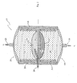
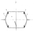
- the invention is provided in an improved pressure vessel, embodiments of which are shown in Figs. 2 and 3.
- the improved pressure vessel is uniquely designed to provide all three pressurized fluids.
- pressure vessel 15 has a vertical axis of elongation x 1 -x 1 , and is shown as having a coaxial cylindrical sidewall structure 16.
- Vehicle axis x-x and pressure vessel axis x 1 -x 1 may be coincident, if desired.
- the upper and lower ends of this sidewall are suitably closed by domed or rounded end heads 18, 19, respectively, that are suitably secured, as by welding or the like, to the adjacent margins of the sidewall.
- Two bellows-like movable wall devices are operatively mounted within the pressure vessel and subdivide the interior space of the pressure vessel into three separate and distinct sealed chambers, indicated at 22, 23 and 24, respectively.
- Upper chamber 22 is arranged to supply its propellant via conduit 25 to engine 12.
- Lower chamber 24 is arranged to supply its propellant via conduit 26 to engine 12.
- the third chamber contains a volatile liquid having a liquid phase and a gaseous phase. Gas from the third chamber is adapted to be provided via a tube, generally indicated at 29.
- the volatile fluid may, for example, be ammonia.
- the third chamber 23 is divided by a screen 28 separating it into upper and lower portions.
- a screen in a propellant tank is often called a propellant management device ("PMA"). It is usually a woven wire cloth that may have individual openings of about 10 micrometers, which is small enough to ensure that the presence of any liquid coming in contact with the screen will not overcome the surface tension force.
- PMA propellant management device
- the third chamber 23 is filled initially under normal gravity so that its volatile liquid level is somewhat below the level of screen 28. Although liquid may come in contact with the screen when the spacecraft is in orbit and experiencing "zero gravity", the surface tension force of the screen prevents any passage of liquid. Since the inlet of tube 23 is located on the upper gas-side of the screen, the thrusters are suppled with gas, not liquid.
- the third fluid is operatively arranged within third chamber 23 and acts through movable walls 20, 21 to pressurize chambers 22 and 24, respectively.
- these chambers are metal bellows that have the same surface area and the same effective spring rate. In fact, they are, for all intents and purposes, identical to one another.
- the common third fluid will pressurize the fluids in the first and second chambers equally. This is important so as to maintain constant the ratio of such fluids as are delivered to the rocket engine 12. As fluid from the first and second chambers are withdrawn in equal amounts, the volume of the third chamber expands symmetrically.
- Fig. 3 shows third chamber 23 as being fully expanded, and chambers 22 and 24 as being compressed to a minimum volume, with all the liquid propellant expelled.
- the convolutions of the metal bellows 30, 31 are nested to a minimum axial length.
- the first and second chambers need not necessarily contain reactive bipropellants. Rather, these chambers could contain a suitable liquid monopropellant.
- the volume of the third chamber expands symmetrically, thus keeping the center of gravity of the propellant supply device substantially fixed relative to the spacecraft.
- the present invention contemplates that many changes and modifications may be made.
- an expanding accordion-like metal bellows as the movable walls
- other types of walls, bladders and diaphragms might possibly to used in lieu thereof.
- the pressurizing third fluid may separate the first and second fluids.
- two balloon-like bladders or containers for the first and second fluids may be provided within the enclosure, with suitable conduits leading to the respective thrust-producing devices.
- the interior volume of the pressure vessel may itself be charged with the volatile liquid to pressurize the first and second balloon-like containers.
- preamble language in a claim that is not referred to in the body of that particular claim is to be construed as a statement of intended use, and not as a limitation. Conversely, where the body of a particular claim does refer to language in the preamble of that particular claim, or a claim to which it refers, such preamble language should be regarded as a limitation on the scope of the claim.
Landscapes
- Engineering & Computer Science (AREA)
- Chemical & Material Sciences (AREA)
- Combustion & Propulsion (AREA)
- Remote Sensing (AREA)
- Aviation & Aerospace Engineering (AREA)
- Mechanical Engineering (AREA)
- General Engineering & Computer Science (AREA)
- Radar, Positioning & Navigation (AREA)
- Filling Or Discharging Of Gas Storage Vessels (AREA)
- Control Of Position, Course, Altitude, Or Attitude Of Moving Bodies (AREA)
Abstract
Description
Claims (13)
- A propellant supply device for a vehicle having a main propulsion motor and having an attitude control system including a plurality of thrusters, comprising:a pressure vessel;first and second movable walls operatively arranged within said pressure vessel and dividing the interior space therewithin into three separate chambers from each of which fluid may be supplied;a first fluid in one of said chambers;a second fluid in a second of said chambers; anda third fluid in a third of said chambers, said third fluid being a volatile liquid having a liquid phase and a gaseous phase, and wherein all three chambers are pressurized to the vapor pressure of said third fluid.
- A propellant supply device as set forth in claim 1 wherein said third chamber is between said movable walls.
- A propellant supply device as set forth in claim 1 wherein said first and second fluids are bipropellants that are adapted to be supplied to said main propulsion motor.
- A propellant supply device as set forth in claim 3 wherein the ratio of fluids discharged from said first and second chambers is substantially constant.
- A propellant supply device as set forth in claim 1 wherein said third fluid is ammonia.
- A propellant supply device as set forth in claim 1 wherein said third fluid is arranged to communicate with said thrusters.
- A propellant supply device as set forth in claim 1 wherein said movable walls have the same effective spring rate.
- A propellant supply device as set forth in claim 1 wherein said movable walls have the same effective area.
- A propellant supply device as set forth in claim 1 wherein each movable wall is a bellows.
- A propellant supply device as set forth in claim 1 wherein said movable walls are so configured and arranged that said first and second fluid are pressurized equally by said third fluid.
- A propellant supply device as set forth in claim 1 wherein said propellant supply device is so configured and arranged that its center of gravity remains substantially fixed independently of the volumes of said fluids.
- A propellant supply device as set forth in claim 1 wherein said first and second fluids are the same.
- A propellant supply device as set forth in claim 12 wherein said first and second fluids are a monopropellant.
Applications Claiming Priority (2)
| Application Number | Priority Date | Filing Date | Title |
|---|---|---|---|
| US10/100,780 US6973773B2 (en) | 2002-03-19 | 2002-03-19 | Propellant supply device |
| US100780 | 2002-03-19 |
Publications (2)
| Publication Number | Publication Date |
|---|---|
| EP1346915A2 true EP1346915A2 (en) | 2003-09-24 |
| EP1346915A3 EP1346915A3 (en) | 2005-11-23 |
Family
ID=27788340
Family Applications (1)
| Application Number | Title | Priority Date | Filing Date |
|---|---|---|---|
| EP03251676A Withdrawn EP1346915A3 (en) | 2002-03-19 | 2003-03-18 | Propellant supply device |
Country Status (3)
| Country | Link |
|---|---|
| US (1) | US6973773B2 (en) |
| EP (1) | EP1346915A3 (en) |
| JP (1) | JP2003312599A (en) |
Cited By (1)
| Publication number | Priority date | Publication date | Assignee | Title |
|---|---|---|---|---|
| CN103293557A (en) * | 2013-04-08 | 2013-09-11 | 北京控制工程研究所 | Method for verifying performance microgravity test of hydraulic accumulator in plate-type propellant management device |
Families Citing this family (8)
| Publication number | Priority date | Publication date | Assignee | Title |
|---|---|---|---|---|
| GB2382847A (en) * | 2001-12-06 | 2003-06-11 | Alstom | Gas turbine wet compression |
| NL1030882C2 (en) * | 2006-01-10 | 2007-07-11 | Erik Jeroen Eenkhoorn | Inflatable element for use and / or use in the interior of a container of a transport or storage device; method for inflating them. |
| JP5352821B2 (en) * | 2008-03-10 | 2013-11-27 | 独立行政法人 宇宙航空研究開発機構 | Liquid fuel storage container and vapor injection system using the container |
| CN109204887A (en) * | 2018-09-06 | 2019-01-15 | 宁波天擎航天科技有限公司 | A kind of aerospace propellant tank |
| CN110332060B (en) * | 2019-03-22 | 2020-10-16 | 蓝箭航天空间科技股份有限公司 | Liquid oxygen methane rocket and liquid oxygen methane rocket tank drop pressure pressurization design method |
| CN112978664B (en) * | 2021-04-28 | 2021-12-07 | 中国科学院空间应用工程与技术中心 | Reusable filling device, system and method applied to spacecraft |
| CN114320664B (en) * | 2022-02-08 | 2024-08-23 | 北京星际荣耀科技有限责任公司 | Anti-freezing and overcooling device and rocket |
| JP2026015829A (en) * | 2024-07-22 | 2026-02-03 | 東洋エンジニアリング株式会社 | Compressed gas storage system and compressed gas storage method |
Family Cites Families (10)
| Publication number | Priority date | Publication date | Assignee | Title |
|---|---|---|---|---|
| US3104526A (en) * | 1959-03-02 | 1963-09-24 | North American Aviation Inc | Positive expulsion tank |
| US3275418A (en) * | 1960-10-13 | 1966-09-27 | Avien Inc | Apparatus for containing a non-rigid or fluid material |
| US3127743A (en) * | 1961-12-28 | 1964-04-07 | Gen Motors Corp | Fluid tank pressurizing system |
| US3222498A (en) * | 1962-05-11 | 1965-12-07 | American Radiator & Standard | Vapor generator |
| US3208358A (en) * | 1962-06-15 | 1965-09-28 | Honeywell Inc | Control apparatus |
| US3170290A (en) * | 1962-07-20 | 1965-02-23 | James E Webb | Liquid rocket system |
| US3614026A (en) | 1969-04-29 | 1971-10-19 | Us Air Force | Self-sustained attitude control system |
| DE4216954C2 (en) * | 1992-05-22 | 1994-08-25 | Manfred Steenborg | Containers, in particular fuel tanks |
| US5471833A (en) | 1993-10-06 | 1995-12-05 | Olin Corporation | Rocket propellant pressurization system using high vapor pressure liquids |
| US5823478A (en) | 1995-07-17 | 1998-10-20 | The University Of British Columbia | Pressure feed for liquid propellant |
-
2002
- 2002-03-19 US US10/100,780 patent/US6973773B2/en not_active Expired - Fee Related
-
2003
- 2003-03-18 JP JP2003117634A patent/JP2003312599A/en active Pending
- 2003-03-18 EP EP03251676A patent/EP1346915A3/en not_active Withdrawn
Cited By (2)
| Publication number | Priority date | Publication date | Assignee | Title |
|---|---|---|---|---|
| CN103293557A (en) * | 2013-04-08 | 2013-09-11 | 北京控制工程研究所 | Method for verifying performance microgravity test of hydraulic accumulator in plate-type propellant management device |
| CN103293557B (en) * | 2013-04-08 | 2015-10-21 | 北京控制工程研究所 | Performance microgravity test of hydraulic accumulator verification method in a kind of plate-type propellant management apparatus |
Also Published As
| Publication number | Publication date |
|---|---|
| US6973773B2 (en) | 2005-12-13 |
| EP1346915A3 (en) | 2005-11-23 |
| US20030177757A1 (en) | 2003-09-25 |
| JP2003312599A (en) | 2003-11-06 |
Similar Documents
| Publication | Publication Date | Title |
|---|---|---|
| US5961074A (en) | Method and apparatus for pressurized feeding of liquid propellants to a rocket engine | |
| US4880185A (en) | Low pressure reaction control propulsion system for a spacecraft | |
| CA1323352C (en) | Low pressure reaction control propulsion system for a spacecraft | |
| US6135393A (en) | Spacecraft attitude and velocity control thruster system | |
| US4723736A (en) | Rocket staging system | |
| US5901557A (en) | Passive low gravity cryogenic storage vessel | |
| US4743278A (en) | Passive propellant management system | |
| US5531067A (en) | Optimized system for feeding a reignitable rocket engine | |
| US4715399A (en) | Liquid-propellant management system for rockets and space vehicles | |
| CN101596939B (en) | Containers for storage of cryogenic liquids and storable power fuels | |
| US6973773B2 (en) | Propellant supply device | |
| US5640844A (en) | Pressurization and control devices using high vapor pressure liquids | |
| US6131858A (en) | Compact single-propellant unitary propulsion system for a small satellite | |
| US4595398A (en) | Propellant acquisition device | |
| Hartwig | A detailed historical review of propellant management devices for low gravity propellant acquisition | |
| US3234728A (en) | Zero-gravity propellant feed system | |
| US11346306B1 (en) | Chemical and cold gas propellant systems and methods | |
| RU2043956C1 (en) | Self-contained rocket pod | |
| US12515821B2 (en) | Reservoir assembly for a spacecraft | |
| US4919367A (en) | Satellite attitude control | |
| US4467985A (en) | Vortex inhibiting closed spherical outlet structure | |
| EP0062678B1 (en) | Vortex inhibiting tank outlet structure | |
| Fester et al. | Space shuttle reaction control subsystem propellant acquisition technology | |
| Biddy et al. | Monopropellant Micropropulsion System for CubeSats | |
| HOOPER, III et al. | Space Shuttle aft propulsion system enhancements |
Legal Events
| Date | Code | Title | Description |
|---|---|---|---|
| PUAI | Public reference made under article 153(3) epc to a published international application that has entered the european phase |
Free format text: ORIGINAL CODE: 0009012 |
|
| AK | Designated contracting states |
Kind code of ref document: A2 Designated state(s): AT BE BG CH CY CZ DE DK EE ES FI FR GB GR HU IE IT LI LU MC NL PT RO SE SI SK TR |
|
| AX | Request for extension of the european patent |
Extension state: AL LT LV MK |
|
| PUAL | Search report despatched |
Free format text: ORIGINAL CODE: 0009013 |
|
| AK | Designated contracting states |
Kind code of ref document: A3 Designated state(s): AT BE BG CH CY CZ DE DK EE ES FI FR GB GR HU IE IT LI LU MC NL PT RO SE SI SK TR |
|
| AX | Request for extension of the european patent |
Extension state: AL LT LV MK |
|
| RIC1 | Information provided on ipc code assigned before grant |
Ipc: 7B 65D 88/62 B Ipc: 7F 02K 9/50 B Ipc: 7B 64G 1/26 B Ipc: 7B 64G 1/40 A |
|
| AKX | Designation fees paid |
Designated state(s): DE ES FR GB IT |
|
| STAA | Information on the status of an ep patent application or granted ep patent |
Free format text: STATUS: THE APPLICATION IS DEEMED TO BE WITHDRAWN |
|
| 18D | Application deemed to be withdrawn |
Effective date: 20060524 |