EP1346893A1 - Hydraulic master cylinder for vehicle with bar handle - Google Patents
Hydraulic master cylinder for vehicle with bar handle Download PDFInfo
- Publication number
- EP1346893A1 EP1346893A1 EP03005701A EP03005701A EP1346893A1 EP 1346893 A1 EP1346893 A1 EP 1346893A1 EP 03005701 A EP03005701 A EP 03005701A EP 03005701 A EP03005701 A EP 03005701A EP 1346893 A1 EP1346893 A1 EP 1346893A1
- Authority
- EP
- European Patent Office
- Prior art keywords
- cylinder
- master cylinder
- hydraulic master
- vehicle
- operation lever
- Prior art date
- Legal status (The legal status is an assumption and is not a legal conclusion. Google has not performed a legal analysis and makes no representation as to the accuracy of the status listed.)
- Granted
Links
Images

Classifications
-
- B—PERFORMING OPERATIONS; TRANSPORTING
- B60—VEHICLES IN GENERAL
- B60T—VEHICLE BRAKE CONTROL SYSTEMS OR PARTS THEREOF; BRAKE CONTROL SYSTEMS OR PARTS THEREOF, IN GENERAL; ARRANGEMENT OF BRAKING ELEMENTS ON VEHICLES IN GENERAL; PORTABLE DEVICES FOR PREVENTING UNWANTED MOVEMENT OF VEHICLES; VEHICLE MODIFICATIONS TO FACILITATE COOLING OF BRAKES
- B60T7/00—Brake-action initiating means
- B60T7/02—Brake-action initiating means for personal initiation
- B60T7/08—Brake-action initiating means for personal initiation hand actuated
- B60T7/10—Disposition of hand control
- B60T7/102—Disposition of hand control by means of a tilting lever
-
- B—PERFORMING OPERATIONS; TRANSPORTING
- B60—VEHICLES IN GENERAL
- B60T—VEHICLE BRAKE CONTROL SYSTEMS OR PARTS THEREOF; BRAKE CONTROL SYSTEMS OR PARTS THEREOF, IN GENERAL; ARRANGEMENT OF BRAKING ELEMENTS ON VEHICLES IN GENERAL; PORTABLE DEVICES FOR PREVENTING UNWANTED MOVEMENT OF VEHICLES; VEHICLE MODIFICATIONS TO FACILITATE COOLING OF BRAKES
- B60T11/00—Transmitting braking action from initiating means to ultimate brake actuator without power assistance or drive or where such assistance or drive is irrelevant
- B60T11/10—Transmitting braking action from initiating means to ultimate brake actuator without power assistance or drive or where such assistance or drive is irrelevant transmitting by fluid means, e.g. hydraulic
- B60T11/16—Master control, e.g. master cylinders
- B60T11/165—Single master cylinders for pressurised systems
-
- B—PERFORMING OPERATIONS; TRANSPORTING
- B62—LAND VEHICLES FOR TRAVELLING OTHERWISE THAN ON RAILS
- B62L—BRAKES SPECIALLY ADAPTED FOR CYCLES
- B62L3/00—Brake-actuating mechanisms; Arrangements thereof
- B62L3/02—Brake-actuating mechanisms; Arrangements thereof for control by a hand lever
- B62L3/023—Brake-actuating mechanisms; Arrangements thereof for control by a hand lever acting on fluid pressure systems
Definitions
- the present invention relates to a hydraulic master cylinder device for a vehicle having a bar handle (a vehicle with a handle bar), in which the brakes and the clutch are operated by a hydraulic pressure generated by a combination of a hydraulic master cylinder and an operation lever in a vehicle having a bar handle, such as a motorcycle, a tricycle, and a three- or four-wheel buggy vehicle. More particularly, the present invention relates to a vertically mounted hydraulic master cylinder device in which the cylinder is mounted in a state that the cylinder opening is directed to a front of the vehicle body
- a hydraulic master cylinder device for hydraulically operating the brakes and the clutch of the vehicle having the bar handle is disclosed in, for example, JP-UM-B-04-34157.
- a cylinder body of the hydraulic master cylinder is mounted on a handle bar, while being oriented in a longitudinal direction of the vehicle body.
- the piston is inserted into a bottomed cylinder bore, which is formed in the cylinder body while being opened in the longitudinal direction of the cylinder body.
- a hydraulic chamber is defined by a bottom of the cylinder bore.
- An operation lever is pivotally supported, by a pivot, on a lever mounting part integral with the cylinder body.
- a push rod is interposed between an operation arm of the operation lever and the piston.
- the piston is pressed toward the bottom of the cylinder bore by the gripping operation of the operation lever.
- the working fluid that is pressurized in the hydraulic chamber is supplied to the brakes and the clutch.
- L1 x F1 L2 x F2
- L1 distance from a gripping point (force application point) P1 of the operation lever to the pivot as a rotational fulcrum of the operation lever
- F1 gripping force of the operation lever
- L2 distance from the pivot to a mounting part of the handle bar of the hydraulic master cylinder
- F2 reaction force acting on the handle bar mounting part of the hydraulic master cylinder.
- the handle bar mounting part of the image forming system lies on and along the center axis of the cylinder, and the distance L2 from the pivot to the handle bar mounting part of the hydraulic master cylinder is short. Accordingly, the reaction force F2 acting on the handle bar mounting part is large. For this reason, in the gripping operation of the operation lever, an excessive moment acts on the cylinder body to thereby cause a flexural deformation in the cylinder body. As a result, lever operation feeling of less rigidity is unfavorably given to a rider.
- an object of the present invention is to provide a hydraulic master cylinder device for a vehicle having a bar handle, which is capable of, at low manufacturing cost, effectively suppressing a flexural deformation of the cylinder body caused by the lever operation, and provides a rigid lever operation feeling.
- a hydraulic master cylinder for vehicle having a bar handle having a hydraulic master cylinder forming a cylinder bore opening toward a front part of a vehicle body and including a piston inserted into the cylinder bore, the hydraulic chamber being defined between the piston and a bottom of the cylinder bore and the hydraulic master cylinder being mounted on a handle bar of the vehicle so as to be oriented in a longitudinal direction of the vehicle body, and an operation lever for pressing the piston toward a bottom of the cylinder bore by gripping and operating the operation lever toward a grip provided on the handle bar, the operation lever being pivotally supported at a lever mounting part of the hydraulic master cylinder, wherein a handle bar mounting part of the hydraulic master cylinder is offset to a position closer to the grip than a center axis of the cylinder.
- the center axis of the cylinder is orthogonal to the handle bar.
- the hydraulic master cylinder for the vehicle having the bar handle further has a push rod disposed between the operation lever and the piston of the hydraulic master cylinder for transmitting a power.
- a hydraulic master cylinder device 1 is composed essentially of a hydraulic master cylinder 2 as a hydraulic pressure generating source, an operation lever 3 for operating the hydraulic master cylinder 2, and a push rod 4 for transmitting a power between the operation lever 3 and the hydraulic master cylinder 2.
- a bracket half body 5a formed integrally with a cylinder body 5 and a half split body bracket 6 separated from the former embraces a handle bar 7 at a front part of a vehicle body. Those brackets 5a and 6 are fastened by bolts 8 to thereby be mounted on a part of the handle bar 7, which is located closer to a front part of the vehicle body.
- the hydraulic master cylinder 2 is of a verticallymounting type in which the cylinder body 5 is disposed in a longitudinal direction of the vehicle body, and the cylinder body 5 contains a bottomed cylinder bore 10 opening toward the front part of the vehicle body, and a center axis of the cylinder CL1 is orthogonal to the handle bar 7.
- a guide pin 12 is provided on a bottom wall of the bottomed cylinder bore 10 into which a piston 11 is inserted, while being protruded along the center axis of the cylinder CL1.
- An accommodating hole 11a for accommodating the guide pin 12 is formed in a front pat of the piston 11.
- the piston 11 is inserted into the cylinder bore 10 in a state that the guide pin 12 is accommodated in the accommodating hole 11a.
- a hydraulic chamber 13 is defined between the piston 11 and a bottom of the cylinder bore 10.
- a return spring 14 is located, in a compressed fashion, between the bottomed cylinder bore 10 and the bottom wall of the accommodating hole 11a.
- the piston 11 is constantly urged toward an opening of the cylinder bore 10 by a resilient force of the return spring 14, and a backward limit of the piston when it is not operated is defined by a contact of the piston with the push rod 4.
- the bracket half body 5a is extended to a rear part of the vehicle body, and a couple of upper and lower lever brackets 5b are protruded from a middle of the vehicle body at a position close to a front part of the vehicle body.
- a relief port 15 and a supply port 16 are formed in an upper wall 5c of the cylinder body 5, while communicating with the cylinder bore 10.
- a horse 18 is connected to a connection pipe 17, and a working fluid flows between a reservoir additionally provided (not shown) and the cylinder bore 10.
- the hydraulic chamber 13 is connected to the front wheel brakes (both are not illustrated) by use of brake horses.
- the working fluid that is pressurized in the hydraulic chamber 13 is supplied to the front wheel brakes which in turn are hydraulically operated.
- the push rod 4 have spherical heads 4a and 4b at both ends.
- the spherical end 4a is placed in a spherical recess 20 of the piston 11.
- the spherical end 4b is placed in a spherical recess 21 formed in an operation arm 3c of the operation lever 3.
- the push rod 4 is disposed as a whole on and along the center axis of the cylinder CL1.
- the operation lever 3 includes a rotational base 3a mounted on the cylinder body 5, a grip operation part 3b extending from the rotational base 3a to and along a portion in front of an acceleration grip 22 (grip of the present invention), and the operation arm 3c for pushing the push rod 4 on the rear side of the vehicle body of the rotational base 3a.
- the rotational base 3a is inserted between the lever brackets 5b of the cylinder body 5, and a pivot 23 is inserted between hem, whereby the operation lever 3 is rotatably mounted on the lever brackets 5b.
- the bracket half body 5a and the half split body bracket 6 combined with the former are disposed on a longitudinal direction line CL2 of the vehicle body, which is offset from the center axis of the cylinder CL1 to the acceleration grip 22, by a distance L3. Accordingly, a center P2 of a mounting part of the hydraulic master cylinder handle bar formed by the bracket half bodies 5a and 6 is also offset from the center axis of the cylinder CL1 to the longitudinal direction line CL2.
- the distance L2 from the pivot 23 to the handle bar mounting part center P2 of the hydraulic master cylinder 2 is longer than the corresponding one in the conventional case by a distance corresponding to the offset since the handle bar mounting part center P2 is offset from the center axis of the cylinder CL1 to the acceleration grip 22 by a distance L3.
- the hydraulic master cylinder device 1 for the vehicle having the bar handle of the instant embodiment is thus constructed.
- a non-operation mode in which the operation lever 3 is not operated by gripping, the operation lever 3, the push rod 4 and the piston 11 are positioned at the backward limit, as shown in Figs. 1 and 2.
- the grip operation part 3b of the operation lever 3 is swung to the acceleration grip 22, the operation lever 3 is rotated about the pivot 23 to the handle bar 7, and the operation arm 3c of the operation lever 3 presses the push rod 4 toward the bottom of the cylinder bore 10.
- the tip of the piston closes the relief port 15 to shut off the communication between the cylinder bore 10 and the reservoir.
- the working fluid in the hydraulic chamber 13 is gradually pressurized and the working fluid of a predetermined pressure is supplied to the front wheel brakes.
- L1 x F1 L2 x F2
- a moment of L1 x F1 acts clockwise in Fig. 1 acts from the operation lever 3.
- a moment L2 x F2 acts on the center P2 of the mounting part of the hydraulic master cylinder 2 counterclockwise in Fig. 1.
- the hydraulic master cylinder 2 is mounted on the handle bar 7 in a state that the center P2 of the mounting part of the handle bar is offset from the center axis of the cylinder CL1 to the acceleration grip 22.
- the distance L2 from the pivot 23 to the center P2 of the handle bar mounting part of the hydraulic master cylinder 2 has an inversely proportional relationship with the reaction force F2. Therefore, the reaction force F2 acting on the center P2 of the handle bar mounting part is reduced by a force corresponding to the increase of the distance L2.
- the hydraulic master cylinder device may be manufactured at low cost.
- hydraulic master cylinder of the present invention may be applied to the rear wheel brakes and clutch, in addition to the front wheel brakes.
- the mounting part of the hydraulic master cylinder to the handle bar is offset to a position closer to the grip than the center axis of the cylinder.
- a flexural deformation acting on the cylinder body by a braking operation is effectively suppressed, so that a rigid lever operation feeling is secured.
- the hydraulic master cylinder device may be manufactured at extremely low cost.
Landscapes
- Engineering & Computer Science (AREA)
- Mechanical Engineering (AREA)
- Transportation (AREA)
- Physics & Mathematics (AREA)
- Fluid Mechanics (AREA)
- Steering Devices For Bicycles And Motorcycles (AREA)
- Transmission Of Braking Force In Braking Systems (AREA)
Abstract
Description
- The present invention relates to a hydraulic master cylinder device for a vehicle having a bar handle (a vehicle with a handle bar), in which the brakes and the clutch are operated by a hydraulic pressure generated by a combination of a hydraulic master cylinder and an operation lever in a vehicle having a bar handle, such as a motorcycle, a tricycle, and a three- or four-wheel buggy vehicle. More particularly, the present invention relates to a vertically mounted hydraulic master cylinder device in which the cylinder is mounted in a state that the cylinder opening is directed to a front of the vehicle body
- A hydraulic master cylinder device for hydraulically operating the brakes and the clutch of the vehicle having the bar handle is disclosed in, for example, JP-UM-B-04-34157.
- In the hydraulic master cylinder device, a cylinder body of the hydraulic master cylinder is mounted on a handle bar, while being oriented in a longitudinal direction of the vehicle body. The piston is inserted into a bottomed cylinder bore, which is formed in the cylinder body while being opened in the longitudinal direction of the cylinder body. A hydraulic chamber is defined by a bottom of the cylinder bore. An operation lever is pivotally supported, by a pivot, on a lever mounting part integral with the cylinder body. A push rod is interposed between an operation arm of the operation lever and the piston. The piston is pressed toward the bottom of the cylinder bore by the gripping operation of the operation lever. The working fluid that is pressurized in the hydraulic chamber is supplied to the brakes and the clutch.
- In the grip operation of the operation lever, the following relation holds:
F1 : gripping force of the operation lever
L2 : distance from the pivot to a mounting part of the handle bar of the hydraulic master cylinder
F2 : reaction force acting on the handle bar mounting part of the hydraulic master cylinder. - In the hydraulic master cylinder device thus constructed, the handle bar mounting part of the image forming system lies on and along the center axis of the cylinder, and the distance L2 from the pivot to the handle bar mounting part of the hydraulic master cylinder is short. Accordingly, the reaction force F2 acting on the handle bar mounting part is large. For this reason, in the gripping operation of the operation lever, an excessive moment acts on the cylinder body to thereby cause a flexural deformation in the cylinder body. As a result, lever operation feeling of less rigidity is unfavorably given to a rider.
- Accordingly, an object of the present invention is to provide a hydraulic master cylinder device for a vehicle having a bar handle, which is capable of, at low manufacturing cost, effectively suppressing a flexural deformation of the cylinder body caused by the lever operation, and provides a rigid lever operation feeling.
- To achieve the above object, there is provided a hydraulic master cylinder for vehicle having a bar handle having a hydraulic master cylinder forming a cylinder bore opening toward a front part of a vehicle body and including a piston inserted into the cylinder bore, the hydraulic chamber being defined between the piston and a bottom of the cylinder bore and the hydraulic master cylinder being mounted on a handle bar of the vehicle so as to be oriented in a longitudinal direction of the vehicle body, and an operation lever for pressing the piston toward a bottom of the cylinder bore by gripping and operating the operation lever toward a grip provided on the handle bar, the operation lever being pivotally supported at a lever mounting part of the hydraulic master cylinder, wherein a handle bar mounting part of the hydraulic master cylinder is offset to a position closer to the grip than a center axis of the cylinder.
- According to the above construction, it is preferable that the center axis of the cylinder is orthogonal to the handle bar.
- According to the above construction, it is preferable that the hydraulic master cylinder for the vehicle having the bar handle further has a push rod disposed between the operation lever and the piston of the hydraulic master cylinder for transmitting a power.
-
- Fig. 1 is a front view showing a hydraulic master cylinder device showing an embodiment of the present invention; and
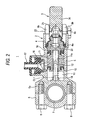
- Fig. 2 is a cross sectional view taken on line II - II in Fig. 1.
-
- An embodiment of the present invention in which the present invention is incorporated into a front wheel brake of a vehicle having a bar handle, will be described with reference to the accompanying drawings. A hydraulic
master cylinder device 1 is composed essentially of ahydraulic master cylinder 2 as a hydraulic pressure generating source, anoperation lever 3 for operating thehydraulic master cylinder 2, and apush rod 4 for transmitting a power between theoperation lever 3 and thehydraulic master cylinder 2. Abracket half body 5a formed integrally with acylinder body 5 and a half splitbody bracket 6 separated from the former embraces ahandle bar 7 at a front part of a vehicle body. Thosebrackets bolts 8 to thereby be mounted on a part of thehandle bar 7, which is located closer to a front part of the vehicle body. - The
hydraulic master cylinder 2 is of a verticallymounting type in which thecylinder body 5 is disposed in a longitudinal direction of the vehicle body, and thecylinder body 5 contains a bottomed cylinder bore 10 opening toward the front part of the vehicle body, and a center axis of the cylinder CL1 is orthogonal to thehandle bar 7. Aguide pin 12 is provided on a bottom wall of the bottomed cylinder bore 10 into which apiston 11 is inserted, while being protruded along the center axis of the cylinder CL1. Anaccommodating hole 11a for accommodating theguide pin 12 is formed in a front pat of thepiston 11. - The
piston 11 is inserted into the cylinder bore 10 in a state that theguide pin 12 is accommodated in theaccommodating hole 11a. Ahydraulic chamber 13 is defined between thepiston 11 and a bottom of the cylinder bore 10. Areturn spring 14 is located, in a compressed fashion, between the bottomed cylinder bore 10 and the bottom wall of theaccommodating hole 11a. Thepiston 11 is constantly urged toward an opening of the cylinder bore 10 by a resilient force of thereturn spring 14, and a backward limit of the piston when it is not operated is defined by a contact of the piston with thepush rod 4. - In the
cylinder body 5, thebracket half body 5a is extended to a rear part of the vehicle body, and a couple of upper andlower lever brackets 5b are protruded from a middle of the vehicle body at a position close to a front part of the vehicle body. Arelief port 15 and asupply port 16 are formed in anupper wall 5c of thecylinder body 5, while communicating with the cylinder bore 10. Ahorse 18 is connected to aconnection pipe 17, and a working fluid flows between a reservoir additionally provided (not shown) and the cylinder bore 10. Thehydraulic chamber 13 is connected to the front wheel brakes (both are not illustrated) by use of brake horses. The working fluid that is pressurized in thehydraulic chamber 13 is supplied to the front wheel brakes which in turn are hydraulically operated. - The
push rod 4 havespherical heads spherical end 4a is placed in aspherical recess 20 of thepiston 11. Thespherical end 4b is placed in aspherical recess 21 formed in anoperation arm 3c of theoperation lever 3. Thepush rod 4 is disposed as a whole on and along the center axis of the cylinder CL1. - The
operation lever 3 includes arotational base 3a mounted on thecylinder body 5, agrip operation part 3b extending from therotational base 3a to and along a portion in front of an acceleration grip 22 (grip of the present invention), and theoperation arm 3c for pushing thepush rod 4 on the rear side of the vehicle body of therotational base 3a. Therotational base 3a is inserted between thelever brackets 5b of thecylinder body 5, and apivot 23 is inserted between hem, whereby theoperation lever 3 is rotatably mounted on thelever brackets 5b. - For the
operation lever 3 thus mounted, the following relation holds
F1 : gripping force applied to a gripping point (force application point) P1
L1 : distance from the gripping point P1 to thepivot 23 as a rotational fulcrum of theoperation lever 3,
L2 : distance from thepivot 23 to a center P2 of the handle bar mounting part of thehydraulic master cylinder 2
F2 : reaction force acting on the mounting part center P2. - While the
cylinder body 5 lies on and along the center axis of the cylinder CL1 orthogonal to thehandle bar 7, thebracket half body 5a and the half splitbody bracket 6 combined with the former are disposed on a longitudinal direction line CL2 of the vehicle body, which is offset from the center axis of the cylinder CL1 to theacceleration grip 22, by a distance L3. Accordingly, a center P2 of a mounting part of the hydraulic master cylinder handle bar formed by thebracket half bodies - Accordingly, the distance L2 from the
pivot 23 to the handle bar mounting part center P2 of thehydraulic master cylinder 2 is longer than the corresponding one in the conventional case by a distance corresponding to the offset since the handle bar mounting part center P2 is offset from the center axis of the cylinder CL1 to theacceleration grip 22 by a distance L3. - The hydraulic
master cylinder device 1 for the vehicle having the bar handle of the instant embodiment is thus constructed. In a non-operation mode in which theoperation lever 3 is not operated by gripping, theoperation lever 3, thepush rod 4 and thepiston 11 are positioned at the backward limit, as shown in Figs. 1 and 2. When in the non-operation mode, thegrip operation part 3b of theoperation lever 3 is swung to theacceleration grip 22, theoperation lever 3 is rotated about thepivot 23 to thehandle bar 7, and theoperation arm 3c of theoperation lever 3 presses thepush rod 4 toward the bottom of thecylinder bore 10. The tip of the piston closes therelief port 15 to shut off the communication between thecylinder bore 10 and the reservoir. Then, the working fluid in thehydraulic chamber 13 is gradually pressurized and the working fluid of a predetermined pressure is supplied to the front wheel brakes. - In gripping operation of the
operation lever 3, as taught by the relation, L1 x F1 = L2 x F2, a moment of L1 x F1 acts clockwise in Fig. 1 acts from theoperation lever 3. a moment L2 x F2 acts on the center P2 of the mounting part of thehydraulic master cylinder 2 counterclockwise in Fig. 1. - The
hydraulic master cylinder 2 is mounted on thehandle bar 7 in a state that the center P2 of the mounting part of the handle bar is offset from the center axis of the cylinder CL1 to theacceleration grip 22. The distance L2 from thepivot 23 to the center P2 of the handle bar mounting part of thehydraulic master cylinder 2 has an inversely proportional relationship with the reaction force F2. Therefore, the reaction force F2 acting on the center P2 of the handle bar mounting part is reduced by a force corresponding to the increase of the distance L2. - As a result, a flexural deformation acting on the
cylinder body 5 by a braking operation is effectively suppressed to thereby secure a rigid operation feeling. Structurally, it is merely required to make a minor change of a mounting shape of thebracket half body 5a of thecylinder body 5. The hydraulic master cylinder device may be manufactured at low cost. - It will readily be understood that the hydraulic master cylinder of the present invention may be applied to the rear wheel brakes and clutch, in addition to the front wheel brakes.
- As seen from the foregoing description, the mounting part of the hydraulic master cylinder to the handle bar is offset to a position closer to the grip than the center axis of the cylinder. A flexural deformation acting on the cylinder body by a braking operation is effectively suppressed, so that a rigid lever operation feeling is secured. To alternate the hydraulic master cylinder, it is merely required to make a minor change of amounting shape of the bracket half body of the cylinder body. Accordingly, the hydraulic master cylinder device may be manufactured at extremely low cost.
Claims (3)
- A hydraulic master cylinder for a vehicle having a bar handle comprising:wherein a handle bar mounting part of the hydraulic master cylinder is offset to a position closer to the grip than a center axis of the cylinder.a hydraulic master cylinder forming a cylinder bore opening toward a front part of a vehicle body and including a piston inserted into the cylinder bore, a hydraulic chamber being defined between the piston and a bottom of the cylinder bore, and the hydraulic master cylinder being mounted on a handle bar of the vehicle so as to be oriented in a longitudinal direction of the vehicle body; andan operation lever for pressing the piston toward a bottom of the cylinder bore by gripping and operating the operation lever toward a grip provided on the handle bar, the operation lever being pivotally supported at a lever mounting part of the hydraulic master cylinder,
- The hydraulic master cylinder for the vehicle having the bar handle according to claim 1, the center axis of the cylinder is orthogonal to the handle bar.
- The hydraulic master cylinder for the vehicle having the bar handle according to claim 1 or 2, further comprising a push rod disposed between the operation lever and the piston of the hydraulic master cylinder for transmitting a power.
Applications Claiming Priority (2)
| Application Number | Priority Date | Filing Date | Title |
|---|---|---|---|
| JP2002074282 | 2002-03-18 | ||
| JP2002074282A JP4086521B2 (en) | 2002-03-18 | 2002-03-18 | Hydraulic master cylinder device for bar handle vehicle |
Publications (2)
| Publication Number | Publication Date |
|---|---|
| EP1346893A1 true EP1346893A1 (en) | 2003-09-24 |
| EP1346893B1 EP1346893B1 (en) | 2005-05-04 |
Family
ID=27785154
Family Applications (1)
| Application Number | Title | Priority Date | Filing Date |
|---|---|---|---|
| EP03005701A Expired - Lifetime EP1346893B1 (en) | 2002-03-18 | 2003-03-13 | Hydraulic master cylinder for vehicle with bar handle |
Country Status (2)
| Country | Link |
|---|---|
| EP (1) | EP1346893B1 (en) |
| JP (1) | JP4086521B2 (en) |
Cited By (2)
| Publication number | Priority date | Publication date | Assignee | Title |
|---|---|---|---|---|
| WO2014111544A3 (en) * | 2013-01-18 | 2014-09-18 | Gustav Magenwirth Gmbh & Co. Kg | Master cylinder device for a hydraulic disk brake |
| CN110254596A (en) * | 2015-03-12 | 2019-09-20 | 什拉姆有限责任公司 | Icycle control device |
Families Citing this family (2)
| Publication number | Priority date | Publication date | Assignee | Title |
|---|---|---|---|---|
| JP4551841B2 (en) * | 2005-08-19 | 2010-09-29 | 日信工業株式会社 | Hydraulic master cylinder device for bar handle vehicle |
| US10618596B2 (en) * | 2016-12-22 | 2020-04-14 | Shimano Inc. | Bicycle operating device |
Citations (3)
| Publication number | Priority date | Publication date | Assignee | Title |
|---|---|---|---|---|
| US5050381A (en) * | 1989-09-13 | 1991-09-24 | Nissin Kogyo Kabushiki Kaisha | Master cylinder with adjustable leverage |
| US6336327B1 (en) * | 1999-08-27 | 2002-01-08 | Honda Giken Kogyo Kabushiki Kaisha | Master cylinder device for vehicles |
| WO2002058988A1 (en) * | 2001-01-24 | 2002-08-01 | Freni Brembo S.P.A. | A master cylinder for vehicles controllable by means of handlebars |
-
2002
- 2002-03-18 JP JP2002074282A patent/JP4086521B2/en not_active Expired - Fee Related
-
2003
- 2003-03-13 EP EP03005701A patent/EP1346893B1/en not_active Expired - Lifetime
Patent Citations (3)
| Publication number | Priority date | Publication date | Assignee | Title |
|---|---|---|---|---|
| US5050381A (en) * | 1989-09-13 | 1991-09-24 | Nissin Kogyo Kabushiki Kaisha | Master cylinder with adjustable leverage |
| US6336327B1 (en) * | 1999-08-27 | 2002-01-08 | Honda Giken Kogyo Kabushiki Kaisha | Master cylinder device for vehicles |
| WO2002058988A1 (en) * | 2001-01-24 | 2002-08-01 | Freni Brembo S.P.A. | A master cylinder for vehicles controllable by means of handlebars |
Cited By (5)
| Publication number | Priority date | Publication date | Assignee | Title |
|---|---|---|---|---|
| WO2014111544A3 (en) * | 2013-01-18 | 2014-09-18 | Gustav Magenwirth Gmbh & Co. Kg | Master cylinder device for a hydraulic disk brake |
| TWI648192B (en) * | 2013-01-18 | 2019-01-21 | 古斯塔夫馬根威爾士兩合有限公司 | Master mounting for a hydraulic disk brake |
| US10189539B2 (en) | 2013-01-18 | 2019-01-29 | Gustav Magenwirth Gmbh & Co. Kg | Master cylinder device for a hydraulic disk brake |
| CN110254596A (en) * | 2015-03-12 | 2019-09-20 | 什拉姆有限责任公司 | Icycle control device |
| CN110254596B (en) * | 2015-03-12 | 2021-04-13 | 什拉姆有限责任公司 | Bicycle control device |
Also Published As
| Publication number | Publication date |
|---|---|
| JP2003267285A (en) | 2003-09-25 |
| EP1346893B1 (en) | 2005-05-04 |
| JP4086521B2 (en) | 2008-05-14 |
Similar Documents
| Publication | Publication Date | Title |
|---|---|---|
| US6336327B1 (en) | Master cylinder device for vehicles | |
| US6390566B1 (en) | Vehicle braking system | |
| CN108657361B (en) | Joystick type vehicle brake device | |
| CN100548763C (en) | Interlocking brake system for bar-handle vehicle | |
| JP3845245B2 (en) | Front / rear wheel brake interlock device in a vehicle | |
| US6719083B2 (en) | Vehicle master cylinder attachment structure | |
| EP1346893B1 (en) | Hydraulic master cylinder for vehicle with bar handle | |
| JP2002220077A (en) | Brake system for bar handle vehicles | |
| CN105452096A (en) | Brake device for vehicle that has handlebars | |
| WO2002058988A1 (en) | A master cylinder for vehicles controllable by means of handlebars | |
| JP6502729B2 (en) | Bar steering wheel control lever | |
| JP3790025B2 (en) | Brake device for motorcycle | |
| CN108698668A (en) | Link braking device | |
| WO2020017333A1 (en) | Brake device for vehicle with handlebar | |
| EP1795420B1 (en) | Interlocking brake system for bar-handle vehicle | |
| JP4121349B2 (en) | Hydraulic master cylinder device for bar handle vehicle | |
| JPH08268369A (en) | Bar handle Vehicle hydraulic master cylinder operating lever | |
| JP2001260975A (en) | Hydraulic master cylinder device for bar handle vehicles | |
| JP3934085B2 (en) | Bar handle vehicle control lever | |
| EP1795421B1 (en) | Brake actuator device for bar-handle vehicle | |
| JP4422676B2 (en) | Interlocking brake mechanism for bar handle vehicles | |
| JP4299713B2 (en) | Hydraulic master cylinder for motorcycles | |
| JP2001018876A (en) | Mechanism for adjusting the grip allowance of the operating lever for bar handle vehicles | |
| JP2005078412A (en) | Bar handle vehicle control lever | |
| JP2001130472A (en) | Hydraulic master cylinder device for bar handle vehicles |
Legal Events
| Date | Code | Title | Description |
|---|---|---|---|
| PUAI | Public reference made under article 153(3) epc to a published international application that has entered the european phase |
Free format text: ORIGINAL CODE: 0009012 |
|
| AK | Designated contracting states |
Kind code of ref document: A1 Designated state(s): AT BE BG CH CY CZ DE DK EE ES FI FR GB GR HU IE IT LI LU MC NL PT RO SE SI SK TR |
|
| AX | Request for extension of the european patent |
Extension state: AL LT LV MK |
|
| 17P | Request for examination filed |
Effective date: 20031203 |
|
| 17Q | First examination report despatched |
Effective date: 20040123 |
|
| AKX | Designation fees paid |
Designated state(s): IT |
|
| REG | Reference to a national code |
Ref country code: DE Ref legal event code: 8566 |
|
| GRAP | Despatch of communication of intention to grant a patent |
Free format text: ORIGINAL CODE: EPIDOSNIGR1 |
|
| GRAS | Grant fee paid |
Free format text: ORIGINAL CODE: EPIDOSNIGR3 |
|
| GRAA | (expected) grant |
Free format text: ORIGINAL CODE: 0009210 |
|
| AK | Designated contracting states |
Kind code of ref document: B1 Designated state(s): IT |
|
| REG | Reference to a national code |
Ref country code: IE Ref legal event code: FG4D |
|
| PLBE | No opposition filed within time limit |
Free format text: ORIGINAL CODE: 0009261 |
|
| STAA | Information on the status of an ep patent application or granted ep patent |
Free format text: STATUS: NO OPPOSITION FILED WITHIN TIME LIMIT |
|
| 26N | No opposition filed |
Effective date: 20060207 |
|
| PGFP | Annual fee paid to national office [announced via postgrant information from national office to epo] |
Ref country code: IT Payment date: 20220210 Year of fee payment: 20 |