EP1346190B1 - Fibre-optical strain gauge and method for the production of said strain gauge - Google Patents
Fibre-optical strain gauge and method for the production of said strain gauge Download PDFInfo
- Publication number
- EP1346190B1 EP1346190B1 EP00984928A EP00984928A EP1346190B1 EP 1346190 B1 EP1346190 B1 EP 1346190B1 EP 00984928 A EP00984928 A EP 00984928A EP 00984928 A EP00984928 A EP 00984928A EP 1346190 B1 EP1346190 B1 EP 1346190B1
- Authority
- EP
- European Patent Office
- Prior art keywords
- fibre
- optical
- mechanical construction
- strain
- construction
- Prior art date
- Legal status (The legal status is an assumption and is not a legal conclusion. Google has not performed a legal analysis and makes no representation as to the accuracy of the status listed.)
- Expired - Lifetime
Links
- 238000000034 method Methods 0.000 title claims description 5
- 238000004519 manufacturing process Methods 0.000 title description 2
- 238000010276 construction Methods 0.000 claims abstract description 66
- 230000003287 optical effect Effects 0.000 claims abstract description 24
- 230000005540 biological transmission Effects 0.000 claims abstract description 7
- 239000013307 optical fiber Substances 0.000 claims abstract description 6
- 230000001419 dependent effect Effects 0.000 claims abstract description 4
- 239000000463 material Substances 0.000 claims description 14
- 238000005476 soldering Methods 0.000 claims description 12
- 238000004026 adhesive bonding Methods 0.000 claims description 11
- 238000003466 welding Methods 0.000 claims description 8
- RYGMFSIKBFXOCR-UHFFFAOYSA-N Copper Chemical compound [Cu] RYGMFSIKBFXOCR-UHFFFAOYSA-N 0.000 claims description 7
- 229910052802 copper Inorganic materials 0.000 claims description 7
- 239000010949 copper Substances 0.000 claims description 7
- 239000003292 glue Substances 0.000 claims description 5
- 239000002184 metal Substances 0.000 claims description 5
- 229910052751 metal Inorganic materials 0.000 claims description 5
- 229910000679 solder Inorganic materials 0.000 claims description 5
- 238000005516 engineering process Methods 0.000 claims description 3
- 238000005259 measurement Methods 0.000 claims description 3
- 238000007711 solidification Methods 0.000 claims description 2
- 230000008023 solidification Effects 0.000 claims description 2
- 239000000835 fiber Substances 0.000 claims 5
- 239000010410 layer Substances 0.000 claims 4
- 229920000728 polyester Polymers 0.000 claims 2
- 239000011152 fibreglass Substances 0.000 claims 1
- 239000011521 glass Substances 0.000 claims 1
- 239000011241 protective layer Substances 0.000 claims 1
- 229910000831 Steel Inorganic materials 0.000 description 1
- NIXOWILDQLNWCW-UHFFFAOYSA-N acrylic acid group Chemical group C(C=C)(=O)O NIXOWILDQLNWCW-UHFFFAOYSA-N 0.000 description 1
- 229910010293 ceramic material Inorganic materials 0.000 description 1
- 150000002739 metals Chemical class 0.000 description 1
- 238000012986 modification Methods 0.000 description 1
- 230000004048 modification Effects 0.000 description 1
- 239000010959 steel Substances 0.000 description 1
Images


Classifications
-
- G—PHYSICS
- G01—MEASURING; TESTING
- G01B—MEASURING LENGTH, THICKNESS OR SIMILAR LINEAR DIMENSIONS; MEASURING ANGLES; MEASURING AREAS; MEASURING IRREGULARITIES OF SURFACES OR CONTOURS
- G01B11/00—Measuring arrangements characterised by the use of optical techniques
- G01B11/16—Measuring arrangements characterised by the use of optical techniques for measuring the deformation in a solid, e.g. optical strain gauge
Definitions
- the present invention relates to a fibre-optical strain gauge of the kind set forth in the preamble of claim 1.
- fibre-optical gauges of this kind it is known to incorporate a mechanical construction which provides a relative movement of oppositely positioned spaced apart first and second optical fibre ends in a direction substantially perpendicular to the axial direction of the optical fibres and using the varying transmission of light between the two fibres as an indication of the parameter to be measured.
- a fibre-optical gauge of this kind is known from US-4,300,813 and although this document does not describe a strain gauge, the document is taken as a starting point for the present invention.
- said movements of the measuring points are eliminated to a large extent by means of the connecting rods comprising articulated connections at both ends, whereby such movements are substantially without influence on the further parts of the mechanical construction which transfers the movement of the measuring points in the strain-measuring direction to the fibre-holding elements.
- Preferred embodiments of the flbre-optical strain gauge the advantages of which will be evident from the following description of preferred embodiments, are revealed in the sub-ordinate claims.
- the mechanical construction 1, schematically shown in Figure 1 includes two connecting rods 2a, 2b, comprising articulated connections to anchorage points 3a, 3b at one end and to further parts of the mechanical construction at the opposite ends.
- the further parts of the mechanical construction is schematically shown as rods connected to move the mounting means 6a, 6b for the optical fibres 7a, 7b mounted thereon.
- the mechanical construction further comprises guiding means 10 for guiding the movement of the mounting means 6a, 6b for the optical fibres 7a, 7b in a direction perpendicular to the axial direction of the optical fibres 7a, 7b.
- any relative movement of the anchorage points 3a, 3b, in a direction 8 along the line connecting the anchorage points 3a, 3b, will be transferred to a corresponding movement of the mounting means 6a, 6b for the optical fibres 7a, 7b.
- Relative movements of the anchorage points 3a, 3b in a plane perpendicular to the strain-measuring direction 8 will substantially not influence the relative position of the mounting means 6a, 6b for the optical fibres 7a, 7b, due to the articulated connections at the ends of the connecting rods 2a, 2b.
- the relative movement of the mounting means 6a, 6b for the fibres 7a, 7b is of the same order of magnitude as the diameter of the optical fibres 7a, 7b. Accordingly, the relative movements of the anchorage points 3a, 3b is of the same order of magnitude both in the strain-measuring direction 8 and in the plane perpendicular to said strain-measuring direction, and accordingly, such movements in said plane will substantially not influence the relative positions of the mounting means 6a, 6b for the optical fibres 7a, 7b, due to the distance provided between the articulated connections at the opposite ends of the connecting rods 2a, 2b.
- the mechanical construction 1 shown schematically in Figure 2 comprises like the Figure 1 construction, two connecting rods 2a, 2b, articulated connected at both ends and at one end being connected to anchorage points 3a, 3b and at the opposite end being connected to a pantograph-like mechanical construction for transferring the movements of the connecting rods 2a, 2b to the mounting means 6a, 6b for the optical fibres 7a, 7b.
- the pantograph-like mechanical construction comprises four rods 5a-5d mutually connected in a mainly square configuration with hinged connections at the corners.
- the mounting means 6a, 6b for the optical fibres 7a, 7b are mounted on oppositely positioned rods 5a, 5c.
- a relative movement of the anchorage points 3a, 3b towards one another provides a relative movement of the mounting means 6a, 6b for the optical fibres 7a, 7b in a direction perpendicular to the axial direction of the optical fibres 7a, 7b.
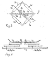
- FIG 3 A mechanical construction functioning in accordance with the principles shown in Figure 2 is shown in Figure 3 .
- This mechanical construction is produced in printed circuit board technology, taking advantage of the high precision production techniques developed for printed circuit boards.
- Other materials can naturally be used for this mechanical construction, such materials e.g. comprising metal, such as steel, plastic materials, such a acrylic, ceramic materials, etc.
- the hinged and articulated connections are provided in the form of parts of the mechanical construction with reduced cross-section.
- the mechanical construction is a layered construction, in which the upper layer consists of the mounting means 6a, 6b for the optical fibres 7a, 7b.
- the optical fibres 7a, 7b can be mounted on the mounting means 6a, 6b by soldering or glueing.
- the optical fibres 7a, 7b are prestressed during the mounting of these on the mounting means and after solidification of the solder or hardening of the glue, the optical fibre is cleaved for providing the two optical fibres 7a, 7b mutually aligned and with a well-defined distance between the optical fibre ends, said distance being dependent on the pre-stressing during mounting.
- the mounting means 6a, 6b are mounted on an intermediate layer defining the mechanical construction which in the shown embodiment comprises the connecting rods 2a, 2b comprising articulated connections at both ends, one end of each connecting rod 2a, 2b being connected to the anchorage points 3a, 3b, and the opposite ends' of said connecting rods 2a, 2b being connected to a pantograph-like configuration 5a, 5b, 5c, 5d, comprising rods 5a-5d in a mainly square configuration and comprising hinged connections at the corners.
- the connecting rods 2a, 2b are articulated connected to opposite corners of the pantograph-like configuration of rods 5a-5d, and two oppositely positioned rods 5a and 5c are connected to the mounting means 6a, 6b by soldering, said soldering being provided on layers of copper on the printed circuit board material.
- soldering being provided on layers of copper on the printed circuit board material.
- This connection could naturally also be provided by glueing, laser welding, etc.
- the mechanical construction is connected to a strain-transferring construction 9 forming the bottom layer of the layered construction, said strain-transferring construction comprising a copper layer on the top surface at the positions for solder connecting to the anchorage points 3a, 3b for the connecting rods 2a, 2b.
- the strain-transferring construction 9 is then glued on to the object to be measured on and the strain movement in the object to be measured on is transferred to the mechanical construction through said strain-transferring construction 9.
- the strain-transferring construction 9 provides a possibility of having a relatively large surface of the measuring system connected to the object to be measured on and still have a relatively short distance between the two anchorage points 3a, 3b, whereby the dynamic range of the fibre-optical strain gauge can be high and the glueing surface for connection to the object to be measured on can be relatively large.
- connection between the anchorage points 3a, 3b and the strain-transferring construction 9 is provided by means of pins mounted in close fitting holes (see Figures 6 and 7 ) in the two parts and supplemented by a flexible glue, whereby a more precise point-like connection is achieved, providing a well-defined distance between the anchorage points.
- Figures 5, 6 and 7 show each of the three layers of the layered construction shown in Figures 3 and 4 .
- Figure 5 shows the upper layer of the mechanical construction, i.e. the fibre-holding elements
- Figure 6 shows the intermediate layer, i.e. the connecting rods 2a, 2b, the pantograph-like configuration of rods 5a-5d
- Figure 7 shows the bottom layer consisting of the strain-transferring construction 9 for mounting on the object to be measured on by glueing.
- the layers of copper and solder or glue provide a certain distance between the printed circuit board mechanical parts, thereby allowing movement of the different layers relative to one another without friction.
Landscapes
- Physics & Mathematics (AREA)
- General Physics & Mathematics (AREA)
- Light Guides In General And Applications Therefor (AREA)
- Optical Transform (AREA)
- Length Measuring Devices By Optical Means (AREA)
Abstract
Description
- The present invention relates to a fibre-optical strain gauge of the kind set forth in the preamble of
claim 1. - In fibre-optical gauges of this kind it is known to incorporate a mechanical construction which provides a relative movement of oppositely positioned spaced apart first and second optical fibre ends in a direction substantially perpendicular to the axial direction of the optical fibres and using the varying transmission of light between the two fibres as an indication of the parameter to be measured. A fibre-optical gauge of this kind is known from
US-4,300,813 and although this document does not describe a strain gauge, the document is taken as a starting point for the present invention. - It is the object of the present invention to provide a fibre-optical strain gauge of the kind referred to above, with which it is possible to provide strain gauge measurements which are substantially not influenced by movements of the measuring points in directions in a plane perpendicular to the desired strain-measuring direction, and this object is achieved with a fibre-optical strain gauge of said kind, which according to the present invention also comprises the features set forth in the characterizing clause of
claim 1. With this arrangement, said movements of the measuring points are eliminated to a large extent by means of the connecting rods comprising articulated connections at both ends, whereby such movements are substantially without influence on the further parts of the mechanical construction which transfers the movement of the measuring points in the strain-measuring direction to the fibre-holding elements. Preferred embodiments of the flbre-optical strain gauge, the advantages of which will be evident from the following description of preferred embodiments, are revealed in the sub-ordinate claims. - In the following detailed part of the present description, the invention will be explained in more detail with reference to the exemplary embodiments of a fibre-optical strain gauge according to the invention shown in the drawings, in which
-
Figure 1 schematically shows the general principle in accordance with the present invention, -
Figures 2 and 2A schematically show the principle of the pantograph-like construction in accordance with a preferred embodiment of the present invention, -
Figure 3 shows a preferred embodiment corresponding toFigure 2 , produced in printed circuit board technology, -
Figure 4 shows the layered structure of theFigure 3 embodiment, -
Figure 5 shows the upper layer of the embodiment in accordance withFigures 3 and 4 , i.e. the fibre-holding elements, -
Figure 6 shows the intermediate layer of the embodiment in accordance withFigures 3 and 4 , i.e. the transferring and guiding mechanical construction, and -
Figure 7 shows the bottom layer of a preferred embodiment in accordance with the present invention, comprising mounting means and glueing surface for connecting to the surface of the construction to be measured on. - The
mechanical construction 1, schematically shown inFigure 1 , includes two connectingrods 2a, 2b, comprising articulated connections toanchorage points optical fibres 7a, 7b mounted thereon. The mechanical construction further comprises guidingmeans 10 for guiding the movement of the mounting means 6a, 6b for theoptical fibres 7a, 7b in a direction perpendicular to the axial direction of theoptical fibres 7a, 7b. In this way, any relative movement of theanchorage points direction 8 along the line connecting theanchorage points optical fibres 7a, 7b. Relative movements of theanchorage points direction 8 will substantially not influence the relative position of the mounting means 6a, 6b for theoptical fibres 7a, 7b, due to the articulated connections at the ends of the connectingrods 2a, 2b. - It is to be understood that the relative movement of the mounting means 6a, 6b for the
fibres 7a, 7b is of the same order of magnitude as the diameter of theoptical fibres 7a, 7b. Accordingly, the relative movements of theanchorage points direction 8 and in the plane perpendicular to said strain-measuring direction, and accordingly, such movements in said plane will substantially not influence the relative positions of the mounting means 6a, 6b for theoptical fibres 7a, 7b, due to the distance provided between the articulated connections at the opposite ends of the connectingrods 2a, 2b. - The
mechanical construction 1 shown schematically inFigure 2 comprises like theFigure 1 construction, two connectingrods 2a, 2b, articulated connected at both ends and at one end being connected toanchorage points rods 2a, 2b to the mounting means 6a, 6b for theoptical fibres 7a, 7b. The pantograph-like mechanical construction comprises fourrods 5a-5d mutually connected in a mainly square configuration with hinged connections at the corners. The mounting means 6a, 6b for theoptical fibres 7a, 7b are mounted on oppositely positionedrods Figure 2A , a relative movement of theanchorage points optical fibres 7a, 7b in a direction perpendicular to the axial direction of theoptical fibres 7a, 7b. - A mechanical construction functioning in accordance with the principles shown in
Figure 2 is shown inFigure 3 . This mechanical construction is produced in printed circuit board technology, taking advantage of the high precision production techniques developed for printed circuit boards. Other materials can naturally be used for this mechanical construction, such materials e.g. comprising metal, such as steel, plastic materials, such a acrylic, ceramic materials, etc. In this construction, the hinged and articulated connections are provided in the form of parts of the mechanical construction with reduced cross-section. As shown inFigure 4 , the mechanical construction is a layered construction, in which the upper layer consists of the mounting means 6a, 6b for theoptical fibres 7a, 7b. Theoptical fibres 7a, 7b can be mounted on the mounting means 6a, 6b by soldering or glueing. In a preferred embodiment, theoptical fibres 7a, 7b are prestressed during the mounting of these on the mounting means and after solidification of the solder or hardening of the glue, the optical fibre is cleaved for providing the twooptical fibres 7a, 7b mutually aligned and with a well-defined distance between the optical fibre ends, said distance being dependent on the pre-stressing during mounting. The mounting means 6a, 6b are mounted on an intermediate layer defining the mechanical construction which in the shown embodiment comprises the connectingrods 2a, 2b comprising articulated connections at both ends, one end of each connectingrod 2a, 2b being connected to theanchorage points rods 2a, 2b being connected to a pantograph-like configuration rods 5a-5d in a mainly square configuration and comprising hinged connections at the corners. The connectingrods 2a, 2b are articulated connected to opposite corners of the pantograph-like configuration ofrods 5a-5d, and two oppositely positionedrods Figure 4 , the mechanical construction is connected to a strain-transferring construction 9 forming the bottom layer of the layered construction, said strain-transferring construction comprising a copper layer on the top surface at the positions for solder connecting to theanchorage points rods 2a, 2b. The strain-transferring construction 9 is then glued on to the object to be measured on and the strain movement in the object to be measured on is transferred to the mechanical construction through said strain-transferring construction 9. The strain-transferring construction 9 provides a possibility of having a relatively large surface of the measuring system connected to the object to be measured on and still have a relatively short distance between the twoanchorage points - In a preferred embodiment, the connection between the
anchorage points Figures 6 and 7 ) in the two parts and supplemented by a flexible glue, whereby a more precise point-like connection is achieved, providing a well-defined distance between the anchorage points. - The
Figures 5, 6 and 7 show each of the three layers of the layered construction shown inFigures 3 and 4 . Thus,Figure 5 shows the upper layer of the mechanical construction, i.e. the fibre-holding elements,Figure 6 shows the intermediate layer, i.e. the connectingrods 2a, 2b, the pantograph-like configuration ofrods 5a-5d, andFigure 7 shows the bottom layer consisting of the strain-transferring construction 9 for mounting on the object to be measured on by glueing. - As can be seen in
Figure 4 , the layers of copper and solder or glue provide a certain distance between the printed circuit board mechanical parts, thereby allowing movement of the different layers relative to one another without friction. - Although the invention above has been described with reference to a specific preferred embodiment, it will be evident that many variations may be possible within the scope of the following claims, such modifications e.g. comprising the use of other materials for the mechanical construction including different materials for different components, the use of other mounting techniques for assembling the components, omission of the separate fibre-
holding elements rods mechanical construction 1 directly on the object to be measured on, using other metals than copper as basis for soldering/welding, substituting glueing, welding, etc. for the suggested soldering etc.
Claims (12)
- Fibre-optical strain gauge comprising a mechanical construction (1) providing a strain-dependent relative movement of oppositely positioned, spaced apart first and second optical fibre ends in a direction substantially perpendicular to the axial direction of the optical fibres (7a, 7b) and using the varying transmission of light between the two fibres (7a, 7b) as an indication of the strain, said mechanical construction comprising fibre-holding elements (6a, 6b) for securing the two fibres (7a, 7b) to the mechanical construction (1) in an aligned relationship in the unstrained condition, characterized by
said mechanical construction (1) further comprisinga) anchorage means (3a, 3b) for providing two substantial pointy-formed connections between the mechanical construction (1) and the object to be measured on, a line (8) through said two connection points (3a, 3b) defining a strain-measuring direction,b) two connecting rods (2a, 2b), comprising articulated connections at both ends, to the respective anchorage means (3a, 3b) at one end and to respective further parts (5a-5d) of the mechanical construction at the other end, respectively, said two rods (2a, 2b) extending substantially in the strain-measuring direction (8),c) a transmission construction, connected articulated to the rod (2a, 2b) ends opposite the respective anchorage means (3a, 3b), for transferring the movement of said rods (2a, 2b) in said strain-measuring direction (8) to the fibre-holding elements (6a, 6b) and for guiding the movement of said fibre-holding elements (6a, 6b) in a direction substantially perpendicular to said axial direction of said optical fibres (7a, 7b). - Fibre-optical strain gauge in accordance with claim 1, characterized by
the transmission construction comprising a pantograph-like structure (5a-5d), in which four rods (5a-5d) in a mainly square or parallelogram-formed configuration are mutually connected at the corners via articulated connections and the connecting rods (2a, 2b) being articulated connected close to two oppositely positioned corners of the mainly square configuration, and the fibre-holding elements (6a, 6b) are connected to two oppositely positioned rods (5a, 5c) of said four rods, at or close to the midpoint of said rods (5a, 5b), whereby said pantograph-like configuration provides the transmission and guidance (mentioned under c) in claim 1). - Fibre-optical strain gauge in accordance with claim 1 or 2, characterized by
the articulated connections being provided in the form of parts of the mechanical construction (1) with reduced cross-section. - Fibre-optical strain gauge in accordance with any of the preceding claims, characterized by the mechanical construction (1) being produced in printed circuit board technology using printed circuit board material, such as glass fibre-enforced polyester printed circuit board material.
- Fibre-optical strain gauge in accordance with claim 4, characterized by
the optical fibre-holding elements (6a, 6b) consisting of printed circuit board material, the optical fibres (7a, 7b) being secured to said elements by soldering or glueing and said elements being secured to the mechanical construction by glueing, soldering or welding, copper or other metal layers being formed on said elements for providing basis for the soldering or welding connections. - Fibre-optical strain gauge in accordance with claim 4 or 5, characterized by the mounting of the mechanical construction (1) to the object to be measured on being provided by glueing, soldering or welding, copper or other metal layers being formed on said elements for providing basis for said soldering or welding.
- Fibre-optical strain gauge in accordance with claim 4 or 5, characterized by
further comprising a strain-transferring construction (9) of printed circuit board material, said strain-transferring construction (9) extending over a substantial distance in the strain-measuring direction (8) and comprising a copper or other metal layer for connecting to the mechanical construction (1) by soldering, welding or glueing and/or holes for pins extending through the strain-transferring construction (9) and the mechanical construction (1) and a surface opposite the connection to the mechanical construction for connecting to the object to be measured on, said connection preferably being provided by glueing. - Fibre-optical strain gauge in accordance with any of the preceding claims, characterized by the fact that the material of the mechanical construction (1,9) is chosen such that its coefficient of thermal expansion in the direction of measurement (8) is adapted to that of the object to be measured.
- Fibre-optical strain gauge in accordance with claim 8, characterized by the fact that the material of the mechanical construction (1,9) has the same coefficient of thermal expansion, in the direction of measurement (8), as the material of the object to be measured.
- Use of a fibre-optical strain gauge in accordance with any of the claims 4-9 for measuring on an object constructed of fibre-glass enforced polyester material, said object e.g. being the wings of a wind turbine.
- Method of mounting optical fibres (7a, 7b) in a strain gauge in accordance with claim 5, characterized by comprising the steps ofa) stripping protective layers from an optical fibre in the area of fixation,b) mounting the stripped fibre in solder and/or glue on the optical fibre-holding elements (6a, 6b) in a prestressed condition,c) after solidification of the solder and/or hardening of the glue, scoring and cleaving the fibre between the fixation points, providing a distance between the resulting fibre ends, said distance being dependent on the pre-stressing of the fibre during mounting.
- Method in accordance with claim 11, characterized by before step b) further comprisingb1) forming a metallized layer on parts of the stripped fibre, at positions corresponding to the positions for mounting to the fibre-holding elements (6a, 6b) by soldering.
Applications Claiming Priority (1)
| Application Number | Priority Date | Filing Date | Title |
|---|---|---|---|
| PCT/DK2000/000725 WO2002052223A1 (en) | 2000-12-22 | 2000-12-22 | Fibre-optical strain gauge and method for the production of said strain gauge |
Publications (2)
| Publication Number | Publication Date |
|---|---|
| EP1346190A1 EP1346190A1 (en) | 2003-09-24 |
| EP1346190B1 true EP1346190B1 (en) | 2012-06-20 |
Family
ID=8149414
Family Applications (1)
| Application Number | Title | Priority Date | Filing Date |
|---|---|---|---|
| EP00984928A Expired - Lifetime EP1346190B1 (en) | 2000-12-22 | 2000-12-22 | Fibre-optical strain gauge and method for the production of said strain gauge |
Country Status (5)
| Country | Link |
|---|---|
| US (1) | US6810749B2 (en) |
| EP (1) | EP1346190B1 (en) |
| AU (1) | AU2001221524B2 (en) |
| ES (1) | ES2388324T3 (en) |
| WO (1) | WO2002052223A1 (en) |
Families Citing this family (7)
| Publication number | Priority date | Publication date | Assignee | Title |
|---|---|---|---|---|
| JP4634508B2 (en) | 2006-07-14 | 2011-02-16 | ビ−エイイ− システムズ パブリック リミテッド カンパニ− | Heat distribution in distributed lighting equipment. |
| US7441464B2 (en) * | 2006-11-08 | 2008-10-28 | Honeywell International Inc. | Strain gauge sensor system and method |
| ATE530966T1 (en) | 2007-02-16 | 2011-11-15 | Rolls Royce Plc | BUOYANCY MEASUREMENT |
| GB2465577A (en) * | 2008-11-21 | 2010-05-26 | Vestas Wind Sys As | Monitoring device for a wind turbine |
| US9683553B2 (en) | 2013-09-06 | 2017-06-20 | General Electric Company | System and method for monitoring wind turbine loading |
| CN103743355B (en) * | 2014-01-13 | 2016-08-31 | 中国科学院武汉岩土力学研究所 | A kind of Portable laser convergence gauge device |
| CN116399251A (en) * | 2023-04-13 | 2023-07-07 | 中国电建集团成都勘测设计研究院有限公司 | Foundation Pit Monitoring System and Method Based on Distributed Optical Fiber |
Family Cites Families (11)
| Publication number | Priority date | Publication date | Assignee | Title |
|---|---|---|---|---|
| US4300813A (en) * | 1979-09-04 | 1981-11-17 | Sperry Corporation | Fiber optic transducer and method of manufacture therefor |
| US4300613A (en) * | 1980-04-14 | 1981-11-17 | Connelly Jerald L | Safety tire having pneumatic tire superimposed on annular cushion |
| US4477725A (en) * | 1981-08-27 | 1984-10-16 | Trw Inc. | Microbending of optical fibers for remote force measurement |
| US4611378A (en) * | 1982-12-20 | 1986-09-16 | Grumman Aerospace Corporation | Method of making a fiber optic strain sensor |
| US5140155A (en) * | 1990-10-17 | 1992-08-18 | Edjewise Sensor Products, Inc. | Fiber optic sensor with dual condition-responsive beams |
| US5402231A (en) * | 1992-08-24 | 1995-03-28 | Mcdonnell Douglas Corporation | Distributed sagnac sensor systems |
| GB9322352D0 (en) * | 1993-10-29 | 1993-12-15 | Univ Brunel | Sensor device |
| US5812251A (en) * | 1994-06-13 | 1998-09-22 | Manesh; Ali | Electro-optic strain gages and transducer |
| US5661246A (en) * | 1996-04-01 | 1997-08-26 | Wanser; Keith H. | Fiber optic displacement sensor for high temperature environment |
| US5841131A (en) * | 1997-07-07 | 1998-11-24 | Schlumberger Technology Corporation | Fiber optic pressure transducers and pressure sensing system incorporating same |
| US6057911A (en) * | 1997-11-17 | 2000-05-02 | Northrop Grumman Corporation | Fiber optic fabry-perot sensor for measuring absolute strain |
-
2000
- 2000-12-22 EP EP00984928A patent/EP1346190B1/en not_active Expired - Lifetime
- 2000-12-22 US US10/451,239 patent/US6810749B2/en not_active Expired - Lifetime
- 2000-12-22 WO PCT/DK2000/000725 patent/WO2002052223A1/en not_active Ceased
- 2000-12-22 ES ES00984928T patent/ES2388324T3/en not_active Expired - Lifetime
- 2000-12-22 AU AU2001221524A patent/AU2001221524B2/en not_active Expired
Also Published As
| Publication number | Publication date |
|---|---|
| US6810749B2 (en) | 2004-11-02 |
| ES2388324T3 (en) | 2012-10-11 |
| WO2002052223A1 (en) | 2002-07-04 |
| US20040035217A1 (en) | 2004-02-26 |
| EP1346190A1 (en) | 2003-09-24 |
| AU2001221524B2 (en) | 2005-02-24 |
Similar Documents
| Publication | Publication Date | Title |
|---|---|---|
| CN102089618B (en) | Temperature compensation optical fiber strain gauge | |
| AU2017232626B2 (en) | Optical alignment of an optical subassembly to an optoelectronic device | |
| CN102317750B (en) | Set of multiaxial force and torque sensor and assembling method | |
| Betz et al. | Advanced layout of a fiber Bragg grating strain gauge rosette | |
| US6810749B2 (en) | Fibre-optical strain gauge and method for the production of said strain gauge | |
| CN114034261B (en) | Miniaturized three-way fiber bragg grating strain sensor | |
| US4830450A (en) | Optical fibre termination | |
| AU2001221524A1 (en) | Fibre-optical strain gauge and method for the production of said strain gauge | |
| WO2001033179A1 (en) | Method of manufacturing a fibre-optical strain-gauge and strain-gauge manufactured by said method | |
| EP0694796A1 (en) | Method of fixing optical fiber array to substrate | |
| GB2196735A (en) | Strain gauges | |
| JP2022181527A (en) | Optical fiber sensor | |
| US6210046B1 (en) | Fiber optic connector with micro-alignable lens having autofocus feature and associated fabrication method | |
| US6302593B1 (en) | Fiber optic connector with micro-alignable lenses and associated fabrication method | |
| CN112880578A (en) | System and method suitable for monitoring dislocation of airport pavement seam structure | |
| JPS59166903A (en) | Manufacture of optical fiber array body | |
| KR100566907B1 (en) | positioning table | |
| US5013110A (en) | Optical fibre end piece for an optical fibre | |
| DE102014218518A1 (en) | Device for detecting deformations of a rotor blade and method for mounting such a device | |
| CN113310461A (en) | Temperature insensitive optical fiber two-dimensional tilt angle sensor | |
| JPH0635201Y2 (en) | Optical fixed attenuator | |
| JP2002311287A (en) | Optical coupling circuit | |
| US20050058409A1 (en) | Strength added epoxy fiber bonding in non-hermetic fiber optic packaging | |
| JPS62196607A (en) | Optical fiber support device | |
| White et al. | Three-axis microactuator for smart optical interconnect system |
Legal Events
| Date | Code | Title | Description |
|---|---|---|---|
| PUAI | Public reference made under article 153(3) epc to a published international application that has entered the european phase |
Free format text: ORIGINAL CODE: 0009012 |
|
| 17P | Request for examination filed |
Effective date: 20030722 |
|
| AK | Designated contracting states |
Kind code of ref document: A1 Designated state(s): AT BE CH CY DE DK ES FI FR GB GR IE IT LI LU MC NL PT SE TR |
|
| AX | Request for extension of the european patent |
Extension state: AL LT LV MK RO SI |
|
| RIN1 | Information on inventor provided before grant (corrected) |
Inventor name: JENSEN, JESPER Inventor name: J RGENSEN, HENRIK, SK RUP Inventor name: KLEMAR, BENNY, AARIS |
|
| RAP1 | Party data changed (applicant data changed or rights of an application transferred) |
Owner name: VESTAS WIND SYSTEMS A/S |
|
| 17Q | First examination report despatched |
Effective date: 20081230 |
|
| RAP1 | Party data changed (applicant data changed or rights of an application transferred) |
Owner name: VESTAS WIND SYSTEMS A/S |
|
| GRAP | Despatch of communication of intention to grant a patent |
Free format text: ORIGINAL CODE: EPIDOSNIGR1 |
|
| GRAS | Grant fee paid |
Free format text: ORIGINAL CODE: EPIDOSNIGR3 |
|
| GRAA | (expected) grant |
Free format text: ORIGINAL CODE: 0009210 |
|
| AK | Designated contracting states |
Kind code of ref document: B1 Designated state(s): AT BE CH CY DE DK ES FI FR GB GR IE IT LI LU MC NL PT SE TR |
|
| REG | Reference to a national code |
Ref country code: GB Ref legal event code: FG4D |
|
| REG | Reference to a national code |
Ref country code: CH Ref legal event code: EP |
|
| REG | Reference to a national code |
Ref country code: AT Ref legal event code: REF Ref document number: 563303 Country of ref document: AT Kind code of ref document: T Effective date: 20120715 |
|
| REG | Reference to a national code |
Ref country code: IE Ref legal event code: FG4D |
|
| REG | Reference to a national code |
Ref country code: DE Ref legal event code: R096 Ref document number: 60047291 Country of ref document: DE Effective date: 20120816 |
|
| REG | Reference to a national code |
Ref country code: ES Ref legal event code: FG2A Ref document number: 2388324 Country of ref document: ES Kind code of ref document: T3 Effective date: 20121011 |
|
| PG25 | Lapsed in a contracting state [announced via postgrant information from national office to epo] |
Ref country code: SE Free format text: LAPSE BECAUSE OF FAILURE TO SUBMIT A TRANSLATION OF THE DESCRIPTION OR TO PAY THE FEE WITHIN THE PRESCRIBED TIME-LIMIT Effective date: 20120620 Ref country code: FI Free format text: LAPSE BECAUSE OF FAILURE TO SUBMIT A TRANSLATION OF THE DESCRIPTION OR TO PAY THE FEE WITHIN THE PRESCRIBED TIME-LIMIT Effective date: 20120620 |
|
| REG | Reference to a national code |
Ref country code: NL Ref legal event code: VDEP Effective date: 20120620 |
|
| REG | Reference to a national code |
Ref country code: AT Ref legal event code: MK05 Ref document number: 563303 Country of ref document: AT Kind code of ref document: T Effective date: 20120620 |
|
| PG25 | Lapsed in a contracting state [announced via postgrant information from national office to epo] |
Ref country code: GR Free format text: LAPSE BECAUSE OF FAILURE TO SUBMIT A TRANSLATION OF THE DESCRIPTION OR TO PAY THE FEE WITHIN THE PRESCRIBED TIME-LIMIT Effective date: 20120921 |
|
| PG25 | Lapsed in a contracting state [announced via postgrant information from national office to epo] |
Ref country code: CY Free format text: LAPSE BECAUSE OF FAILURE TO SUBMIT A TRANSLATION OF THE DESCRIPTION OR TO PAY THE FEE WITHIN THE PRESCRIBED TIME-LIMIT Effective date: 20120620 Ref country code: AT Free format text: LAPSE BECAUSE OF FAILURE TO SUBMIT A TRANSLATION OF THE DESCRIPTION OR TO PAY THE FEE WITHIN THE PRESCRIBED TIME-LIMIT Effective date: 20120620 Ref country code: BE Free format text: LAPSE BECAUSE OF FAILURE TO SUBMIT A TRANSLATION OF THE DESCRIPTION OR TO PAY THE FEE WITHIN THE PRESCRIBED TIME-LIMIT Effective date: 20120620 |
|
| PG25 | Lapsed in a contracting state [announced via postgrant information from national office to epo] |
Ref country code: IT Free format text: LAPSE BECAUSE OF FAILURE TO SUBMIT A TRANSLATION OF THE DESCRIPTION OR TO PAY THE FEE WITHIN THE PRESCRIBED TIME-LIMIT Effective date: 20120620 Ref country code: PT Free format text: LAPSE BECAUSE OF FAILURE TO SUBMIT A TRANSLATION OF THE DESCRIPTION OR TO PAY THE FEE WITHIN THE PRESCRIBED TIME-LIMIT Effective date: 20121022 |
|
| PG25 | Lapsed in a contracting state [announced via postgrant information from national office to epo] |
Ref country code: NL Free format text: LAPSE BECAUSE OF FAILURE TO SUBMIT A TRANSLATION OF THE DESCRIPTION OR TO PAY THE FEE WITHIN THE PRESCRIBED TIME-LIMIT Effective date: 20120620 |
|
| PLBE | No opposition filed within time limit |
Free format text: ORIGINAL CODE: 0009261 |
|
| STAA | Information on the status of an ep patent application or granted ep patent |
Free format text: STATUS: NO OPPOSITION FILED WITHIN TIME LIMIT |
|
| PG25 | Lapsed in a contracting state [announced via postgrant information from national office to epo] |
Ref country code: DK Free format text: LAPSE BECAUSE OF FAILURE TO SUBMIT A TRANSLATION OF THE DESCRIPTION OR TO PAY THE FEE WITHIN THE PRESCRIBED TIME-LIMIT Effective date: 20120620 |
|
| 26N | No opposition filed |
Effective date: 20130321 |
|
| REG | Reference to a national code |
Ref country code: DE Ref legal event code: R097 Ref document number: 60047291 Country of ref document: DE Effective date: 20130321 |
|
| PG25 | Lapsed in a contracting state [announced via postgrant information from national office to epo] |
Ref country code: MC Free format text: LAPSE BECAUSE OF NON-PAYMENT OF DUE FEES Effective date: 20121231 |
|
| REG | Reference to a national code |
Ref country code: CH Ref legal event code: PL |
|
| REG | Reference to a national code |
Ref country code: IE Ref legal event code: MM4A |
|
| PG25 | Lapsed in a contracting state [announced via postgrant information from national office to epo] |
Ref country code: LI Free format text: LAPSE BECAUSE OF NON-PAYMENT OF DUE FEES Effective date: 20121231 Ref country code: IE Free format text: LAPSE BECAUSE OF NON-PAYMENT OF DUE FEES Effective date: 20121222 Ref country code: CH Free format text: LAPSE BECAUSE OF NON-PAYMENT OF DUE FEES Effective date: 20121231 |
|
| PG25 | Lapsed in a contracting state [announced via postgrant information from national office to epo] |
Ref country code: TR Free format text: LAPSE BECAUSE OF FAILURE TO SUBMIT A TRANSLATION OF THE DESCRIPTION OR TO PAY THE FEE WITHIN THE PRESCRIBED TIME-LIMIT Effective date: 20120620 |
|
| PG25 | Lapsed in a contracting state [announced via postgrant information from national office to epo] |
Ref country code: LU Free format text: LAPSE BECAUSE OF NON-PAYMENT OF DUE FEES Effective date: 20121222 |
|
| REG | Reference to a national code |
Ref country code: FR Ref legal event code: PLFP Year of fee payment: 16 |
|
| REG | Reference to a national code |
Ref country code: FR Ref legal event code: CA Effective date: 20160602 |
|
| REG | Reference to a national code |
Ref country code: FR Ref legal event code: PLFP Year of fee payment: 17 |
|
| REG | Reference to a national code |
Ref country code: FR Ref legal event code: PLFP Year of fee payment: 18 |
|
| PGFP | Annual fee paid to national office [announced via postgrant information from national office to epo] |
Ref country code: FR Payment date: 20181231 Year of fee payment: 19 Ref country code: GB Payment date: 20181221 Year of fee payment: 19 |
|
| PGFP | Annual fee paid to national office [announced via postgrant information from national office to epo] |
Ref country code: DE Payment date: 20190228 Year of fee payment: 19 Ref country code: ES Payment date: 20190131 Year of fee payment: 19 |
|
| REG | Reference to a national code |
Ref country code: DE Ref legal event code: R119 Ref document number: 60047291 Country of ref document: DE |
|
| GBPC | Gb: european patent ceased through non-payment of renewal fee |
Effective date: 20191222 |
|
| PG25 | Lapsed in a contracting state [announced via postgrant information from national office to epo] |
Ref country code: GB Free format text: LAPSE BECAUSE OF NON-PAYMENT OF DUE FEES Effective date: 20191222 Ref country code: DE Free format text: LAPSE BECAUSE OF NON-PAYMENT OF DUE FEES Effective date: 20200701 Ref country code: FR Free format text: LAPSE BECAUSE OF NON-PAYMENT OF DUE FEES Effective date: 20191231 |
|
| REG | Reference to a national code |
Ref country code: ES Ref legal event code: FD2A Effective date: 20210524 |
|
| PG25 | Lapsed in a contracting state [announced via postgrant information from national office to epo] |
Ref country code: ES Free format text: LAPSE BECAUSE OF NON-PAYMENT OF DUE FEES Effective date: 20191223 |