EP1345669B1 - Apparatus and method for wet filtering machine exhaust - Google Patents
Apparatus and method for wet filtering machine exhaust Download PDFInfo
- Publication number
- EP1345669B1 EP1345669B1 EP00935935A EP00935935A EP1345669B1 EP 1345669 B1 EP1345669 B1 EP 1345669B1 EP 00935935 A EP00935935 A EP 00935935A EP 00935935 A EP00935935 A EP 00935935A EP 1345669 B1 EP1345669 B1 EP 1345669B1
- Authority
- EP
- European Patent Office
- Prior art keywords
- oil
- container
- anyone
- filter sticks
- filter
- Prior art date
- Legal status (The legal status is an assumption and is not a legal conclusion. Google has not performed a legal analysis and makes no representation as to the accuracy of the status listed.)
- Expired - Lifetime
Links
- 238000001914 filtration Methods 0.000 title claims abstract description 26
- 238000000034 method Methods 0.000 title claims abstract description 21
- CBENFWSGALASAD-UHFFFAOYSA-N Ozone Chemical compound [O-][O+]=O CBENFWSGALASAD-UHFFFAOYSA-N 0.000 claims abstract description 8
- 239000003921 oil Substances 0.000 claims description 81
- 229920001821 foam rubber Polymers 0.000 claims description 16
- 239000000341 volatile oil Substances 0.000 claims description 11
- 239000003344 environmental pollutant Substances 0.000 claims description 6
- 239000004033 plastic Substances 0.000 claims description 6
- 231100000719 pollutant Toxicity 0.000 claims description 6
- 230000005484 gravity Effects 0.000 claims description 4
- 239000006260 foam Substances 0.000 claims description 2
- 239000012080 ambient air Substances 0.000 abstract description 4
- 239000000203 mixture Substances 0.000 abstract description 3
- 239000013618 particulate matter Substances 0.000 abstract description 2
- 239000003570 air Substances 0.000 description 9
- 230000002411 adverse Effects 0.000 description 5
- 238000003915 air pollution Methods 0.000 description 5
- 239000012530 fluid Substances 0.000 description 5
- 230000035943 smell Effects 0.000 description 4
- XLYOFNOQVPJJNP-UHFFFAOYSA-N water Substances O XLYOFNOQVPJJNP-UHFFFAOYSA-N 0.000 description 4
- 238000004140 cleaning Methods 0.000 description 3
- 239000000428 dust Substances 0.000 description 3
- 229920001971 elastomer Polymers 0.000 description 3
- PEDCQBHIVMGVHV-UHFFFAOYSA-N Glycerine Chemical compound OCC(O)CO PEDCQBHIVMGVHV-UHFFFAOYSA-N 0.000 description 2
- 230000036541 health Effects 0.000 description 2
- 239000000463 material Substances 0.000 description 2
- 238000013021 overheating Methods 0.000 description 2
- 239000002245 particle Substances 0.000 description 2
- 230000008569 process Effects 0.000 description 2
- 206010015946 Eye irritation Diseases 0.000 description 1
- 206010019233 Headaches Diseases 0.000 description 1
- 206010043521 Throat irritation Diseases 0.000 description 1
- 239000002253 acid Substances 0.000 description 1
- 239000000809 air pollutant Substances 0.000 description 1
- 231100001243 air pollutant Toxicity 0.000 description 1
- 230000015556 catabolic process Effects 0.000 description 1
- 230000008859 change Effects 0.000 description 1
- 238000006243 chemical reaction Methods 0.000 description 1
- 238000010276 construction Methods 0.000 description 1
- 230000007547 defect Effects 0.000 description 1
- 230000002939 deleterious effect Effects 0.000 description 1
- 239000003599 detergent Substances 0.000 description 1
- 238000010410 dusting Methods 0.000 description 1
- 230000000694 effects Effects 0.000 description 1
- 230000007613 environmental effect Effects 0.000 description 1
- 238000001704 evaporation Methods 0.000 description 1
- 230000008020 evaporation Effects 0.000 description 1
- 231100000013 eye irritation Toxicity 0.000 description 1
- 239000000835 fiber Substances 0.000 description 1
- 239000011521 glass Substances 0.000 description 1
- 235000011187 glycerol Nutrition 0.000 description 1
- 231100000869 headache Toxicity 0.000 description 1
- 230000008821 health effect Effects 0.000 description 1
- 230000005802 health problem Effects 0.000 description 1
- 238000003780 insertion Methods 0.000 description 1
- 230000037431 insertion Effects 0.000 description 1
- 230000007794 irritation Effects 0.000 description 1
- 238000012986 modification Methods 0.000 description 1
- 230000004048 modification Effects 0.000 description 1
- 230000000737 periodic effect Effects 0.000 description 1
- 229920001296 polysiloxane Polymers 0.000 description 1
- 229920006395 saturated elastomer Polymers 0.000 description 1
- 239000007787 solid Substances 0.000 description 1
- 239000004753 textile Substances 0.000 description 1
- 230000032258 transport Effects 0.000 description 1
Images


Classifications
-
- B—PERFORMING OPERATIONS; TRANSPORTING
- B01—PHYSICAL OR CHEMICAL PROCESSES OR APPARATUS IN GENERAL
- B01D—SEPARATION
- B01D45/00—Separating dispersed particles from gases or vapours by gravity, inertia, or centrifugal forces
- B01D45/04—Separating dispersed particles from gases or vapours by gravity, inertia, or centrifugal forces by utilising inertia
- B01D45/08—Separating dispersed particles from gases or vapours by gravity, inertia, or centrifugal forces by utilising inertia by impingement against baffle separators
- B01D45/10—Separating dispersed particles from gases or vapours by gravity, inertia, or centrifugal forces by utilising inertia by impingement against baffle separators which are wetted
-
- B—PERFORMING OPERATIONS; TRANSPORTING
- B01—PHYSICAL OR CHEMICAL PROCESSES OR APPARATUS IN GENERAL
- B01D—SEPARATION
- B01D50/00—Combinations of methods or devices for separating particles from gases or vapours
- B01D50/60—Combinations of devices covered by groups B01D46/00 and B01D47/00
-
- B—PERFORMING OPERATIONS; TRANSPORTING
- B01—PHYSICAL OR CHEMICAL PROCESSES OR APPARATUS IN GENERAL
- B01D—SEPARATION
- B01D53/00—Separation of gases or vapours; Recovering vapours of volatile solvents from gases; Chemical or biological purification of waste gases, e.g. engine exhaust gases, smoke, fumes, flue gases, aerosols
- B01D53/14—Separation of gases or vapours; Recovering vapours of volatile solvents from gases; Chemical or biological purification of waste gases, e.g. engine exhaust gases, smoke, fumes, flue gases, aerosols by absorption
- B01D53/18—Absorbing units; Liquid distributors therefor
-
- G—PHYSICS
- G03—PHOTOGRAPHY; CINEMATOGRAPHY; ANALOGOUS TECHNIQUES USING WAVES OTHER THAN OPTICAL WAVES; ELECTROGRAPHY; HOLOGRAPHY
- G03G—ELECTROGRAPHY; ELECTROPHOTOGRAPHY; MAGNETOGRAPHY
- G03G21/00—Arrangements not provided for by groups G03G13/00 - G03G19/00, e.g. cleaning, elimination of residual charge
- G03G21/20—Humidity or temperature control also ozone evacuation; Internal apparatus environment control
- G03G21/206—Conducting air through the machine, e.g. for cooling, filtering, removing gases like ozone
-
- B—PERFORMING OPERATIONS; TRANSPORTING
- B01—PHYSICAL OR CHEMICAL PROCESSES OR APPARATUS IN GENERAL
- B01D—SEPARATION
- B01D2257/00—Components to be removed
- B01D2257/10—Single element gases other than halogens
- B01D2257/106—Ozone
Definitions
- ozone a gas called ozone.
- Health problems associated with ozone gas pollution include headaches, eye irritation, nose irritation, throat irritation and dryness to the eyes, nose and throat.
- toner dust and particulate matter can present further health risks to office machine users.
- the document DE 328 826 C discloses an apparatus for wet filtering of machine exhaust and a method therefore.
- a housing provided with a channel for machine exhaust is provided with filter sticks which are arranged in vertical manner.
- the filter sticks are rods or perforated tubes coated with wood-chip or textile fibre and they are affixed at a bottom portion of the channel with their upper end portion whereby a lower end portion of the filter sticks is arranged in a bath which can contain water, glycerine or the like.
- the material of the filter sticks adsorbs the fluid of the bath and transports it into the channel portion through which machine exhaust is flowing through. Pollutions adhere to the filter sticks.
- the fluid evaporates from the filter sticks in the filter channel.
- the US 1,989,773 describes a de-dusting apparatus for removing dust from a gas flowing through said filter.
- a housing is provided with a channel for a gas stream flowing through the filter housing.
- filter sticks which are affixed in vertical manner between a upper and a lower wall of said channel.
- the lower wall is provided with openings for removing a filter fluid that is flowing downwards at certain portions of the filter sticks.
- they are supplied with a cleaning fluid from a container being arranged above the channel and having a plurality of openings supplying the fluid to certain portions of the filter sticks that are directed opposite to the gas stream.
- pressure cleaning is provided by a valve controlled supply pipe which is provided for every filter stick.
- the present invention answers these needs by providing a wet filter apparatus and method for filtering office machine exhaust, and providing a more desirable scent to users.
- the present invention provides an apparatus and method for filtering office machine exhaust to reduce health-risks to users and internal damage to machines.
- the present invention further provides an apparatus and method for filtering office machine exhuast that can be used by machine users that are non-technicians.
- An aspect of the present invention is a wet filtering apparatus and method for limiting the expulsion of ozone and toner and particulate pollutants from office machines into the ambient air.
- a further aspect of the present invention is the conducting of ethereal oils along a foam filter stick to remove air pollutants from office machine exhaust.
- a further aspect of the present invention is to provide desirable scented oils to control adverse smells from office machine exhaust.
- the present invention relates to an apparatus and method for wet filtering machine exhaust.
- an apparatus and method for filtering the exhaust of office machines such as copiers, printers, and facsimile machines, with oil conducted along a filter medium is disclosed.
- office machines such as copiers, printers, and facsimile machines
- oil conducted along a filter medium is disclosed.
- the present invention is described with regard to filtration of office machine exhaust, those of ordinary skill in the art will appreciate that the present invention is adaptable to variety of machines in which gas and particulate pollutants are desirably filtered from entering the ambient air.
- a filter apparatus of the present invention includes three main parts: (i) a housing with filter sticks; (ii) two oil containers, one for delivering oil along the filter sticks and the other for receiving the delivered oil; and (iii) a wide range of ethereal oils provided with desired scents.
- a filter housing (3) of the filter apparatus of the present invention is disclosed.
- the housing is of rectangular shape with two side walls (62), a top wall (64), and a bottom wall (65).
- the housing preferably comprises heat-resistant plastic, which is able to withstand a temperature of at least 60° Celsius.
- the external appearance of the housing is preferably rectangular, the housing may be square, rectangular, round, or custom-shaped based on the exhaust opening of a machine which the filter apparatus covers.
- Adjacent to each of the upper top and bottom walls are preferably two oil container holding areas (110).
- Each of the holding areas preferably includes a back wall (27).
- a catch opening (25) is preferably provided along each of the back walls (27) for receiving a catch from the oil container.
- a locking projection (20) is further preferably provided along the bottom face of each of the holding areas for locking the respective oil containers in place.
- a holding area base plate (69) is provided with a plurality of housing filter stick openings (30).
- the bottom holding area is enclosed by a base plate (67) with a plurality of housing filter stick openings (30).
- Each filter stick opening (30) of base plate (69) has a corresponding filter stick opening in parallel base plate (67).
- the filter stick's filtering section (4), the area between parallel base plates (67) and (69), preferably comprises a plurality of filter sticks (50) for conducting oil from the openings (30) in base plate (69) to the corresponding openings (30) in base plate (67).
- an air outflow opening 60 is provided in each of the side walls (62) in each of the side walls (62).
- an oblong exhaust slit is preferably located on the left and right side of the housing. The exhaust slits preferably prevent excess pressure in the filter itself, since, as a result of them, the backed up or excessively produced air quantities have the possibility of being able to exit on both sides.
- one or more brackets (40) attach a side wall (62) to an office machine.
- the filter apparatus is preferably secured with filtering section (4) placed in front of the exhaust of the office machine.
- filtering section (4) placed in front of the exhaust of the office machine.
- the attachment bracket (40) may be a single bracket or a plurality of brackets on any one or more of the walls of the housing, depending on the machine to which the filter apparatus is attached. Housing attachments, in any form, are primarily based on the respective type of machine to which the housing is to be applied. As a result, the attachment bracket contemplates a variety of attachment means, including plastic brackets and click systems.
- an upper and lower oil container opening (70) is provided for insertion and removal of the oil containers.
- an oil container (10) filled with oil (5) is disclosed.
- the oil container preferably includes a bottom face, a left and right face, and a front and back face.
- the top of the container is preferably open for filling the container with oil out of the filter housing.
- a container When placed in the filter housing, a container is either closed by top wall (64) or base plate (67), depending on whether the container is an upper or lower container.
- an oil filling device may be integrated with the housing and an upper oil container without removing the container from the housing.
- the bottom face of the oil container preferably includes a plurality of oil flow openings (16).
- An oil pad (15) preferably covers the openings to slow and control the flow of oil (5) to the openings (16).
- the bottom third is filled by the pad (15), which is preferably a rubber foam pad.
- a catch (12) is preferably attached on the back face of the oil container.
- the front face of the oil container preferably includes a grip rail (11) for sliding the oil container in and out of the filter housing.
- a viewing glass (13) is also preferably provided on the front face of the oil container for a user to examine the remaining oil level.
- the bottom of the oil container preferably includes one or more locking clips to secure the oil container at the locking clip projection (20) of the housing.
- the locking clips also receive a rubber closure for closing the flow openings (16).
- the rubber closure preferably slides between the locking clips (14) and can be inserted or removed as needed to prevent or allow the flow of oil from the openings.
- an oil container (10) filled with oil and without closure (18) is inserted through upper opening (70) into the upper container holding area (110) of the filter housing (3).
- the oil container catch (12) connects into catch opening (25).
- Locking clips (14) preferably connect to one or more locking projections (20) by a click locking system to prevent the containers from falling out.
- the plurality of flow openings (16) are adjacent to filter stick openings (30).
- the second oil container (10) initially does not contain oil and includes rubber closure (18) to close the plurality of flow openings (16).
- the second oil container is inserted into lower holding area (110) of the housing.
- the open top of the lower oil container is preferably adjacent to the plurality of filter stick openings in base plate (67) of the housing.
- oil (5) in the upper oil container slowly flows through the pad (15) to and through the oil flow openings (16) and into the filter stick openings (30). Gravity causes the oil to flow (90) downward along the plurality of filter sticks (50). The oil continues to flow downward to the filter stick openings (30) in base plate (67). The oil subsequently drips off into the lower oil container.
- exhaust (120) from an office machine blows through the filtering section of the filter apparatus. Ozone particulates, and other pollutants contact the oil along filter sticks (50) and are removed from the exhaust. Filtered air (125) flows out of the filtering section (4) and into the ambient air from the filter apparatus.
- the filters sticks (50) are preferably round, perpendicularly standing foam rubber rods of approx. 5-6 mm in diameter and a perforated plastic surface which are perpendicular and staggered to one another.
- the filter sticks may be of various shapes including oval, square, rectangular, triangular, and other shapes.
- the filter sticks are preferably a fixed component and are attached to the housing at the corresponding filter stick openings in base plates (67) and (69).
- the filter sticks are also preferably perpendicular in order to enable the automatic flow of oil by gravity.
- the filter sticks are further preferably staggered, in order to force the outflowing air quantities to flow around the foam rubber rods.
- the distance from one foam rubber rod to another preferably is no greater than 2 mm.
- a security ring (130) is provided in the preferred embodiment to maintain the distance between the filter sticks.
- the filter sticks are preferably maintained perpendicular to base plates (67) and (69), and parallel to one another.
- the foam rubber material of the filter sticks preferably prevents a rapid flow of oil from the full upper oil container into the lower empty oil container.
- the individual foam rubber rod is preferably mechanically strengthened internally by the perforated plastic surface (simultaneously a mechanical protection against external damage, such as during cleaning).
- the perforation permanently allows low moisture on the external surface of the rods.
- microscopically small particles which are located in the exhaust flowing out of a machine by means of ventilators are preferably captured and deposited on the external cover of the foam rubber rods (the finest toner particles, oil residues, silicones, oils of all types, as well as dust and environmental air pollution).
- the oil (5) is ethereal oil, which may have a desired scent.
- the desired scent from the ethereal oil is provided into the air by the warm air from the exhaust of an office machine. Accordingly, both filtration and a desirable scent are achieved by the filter apparatus.
- an oil container is filled with ethereal oil of a desirable scent and placed in the upper oil container holding area.
- a second, empty oil container is placed into the lower container holding area.
- Each of these oil containers preferably comprises heat-resistant and acid-resistant and mechanically solid plastic.
- each container full or empty
- the lower part of the interior side of the container is designed with a foam rubber pad (along the entire length and over all openings into which the foam rubber rods lock). This foam rubber pad preferably fills approximately the lower third of the entire container and will draw the ethereal oil, but only slowly allow it to pass through to the foam rubber rods.
- the containers may be switched.
- the closure on the lower container is removed, opening the oil flow openings, and the lower container is inserted into the upper container holding area.
- the closure is inserted at the base of the empty upper container, thereby closing the oil openings, and the empty container is inserted into the lower holding area.
- this process may be repeated for up to three months, depending on the rate of loss of the ethereal oil mixture.
- the filter sticks are preferably washable.
- the filter apparatus may be removed from the machine and washed with a cleansing agent, such as water, to remove the pollutants which build-up on the filter sticks.
- the filter housing may be discarded, and a filter apparatus with fresh filter sticks may be attached at desired filter-changing intervals for the office machine.
- Ethereal oils have very good properties for controlled flow and filtering.
- lime-free normal water may be added to ethereal oil to achieve desired flow rates and filtering reactions.
- the ratio of oil and water mixture is determined based on parameters such as humidity, temperature, evaporation rate, scent of oil, rate of exhaust flow, and type of filter sticks.
Landscapes
- Chemical & Material Sciences (AREA)
- Chemical Kinetics & Catalysis (AREA)
- Engineering & Computer Science (AREA)
- General Physics & Mathematics (AREA)
- General Chemical & Material Sciences (AREA)
- Biodiversity & Conservation Biology (AREA)
- Ecology (AREA)
- Environmental & Geological Engineering (AREA)
- Environmental Sciences (AREA)
- Physics & Mathematics (AREA)
- Life Sciences & Earth Sciences (AREA)
- Analytical Chemistry (AREA)
- Atmospheric Sciences (AREA)
- Oil, Petroleum & Natural Gas (AREA)
- Filtering Of Dispersed Particles In Gases (AREA)
- Control Or Security For Electrophotography (AREA)
- Filtering Materials (AREA)
- Electrical Discharge Machining, Electrochemical Machining, And Combined Machining (AREA)
- Treating Waste Gases (AREA)
- Separation Of Particles Using Liquids (AREA)
- Air Filters, Heat-Exchange Apparatuses, And Housings Of Air-Conditioning Units (AREA)
Abstract
Description
- During the process of printing, laser printers and copy machines produce a gas called ozone. Health problems associated with ozone gas pollution include headaches, eye irritation, nose irritation, throat irritation and dryness to the eyes, nose and throat. In addition to ozone gas, toner dust and particulate matter can present further health risks to office machine users.
- Most existing office machines are equipped with filters to alleviate the adverse affects of air pollution. However, a printer's or copy machine's temperature may rise by over 10% due to filter clogging. The clogged filter also makes the fan slow down due to reduced air flow, which in turn can produce increased printed page defects and also increase the danger of major components failing.
- Although periodic filter replacement can cut down on the health risks and adverse financial impact associated with office machine air pollution, many filters are not easily accessible to non-technicians. Further, because saturated and clogged filters cause machine breakdown, many persons simply remove a machine filter rather than properly replacing it. As a result, many office machines have no filters, increasing air pollution and the risks associated with the pollution.
- The document
DE 328 826 C discloses an apparatus for wet filtering of machine exhaust and a method therefore. A housing provided with a channel for machine exhaust is provided with filter sticks which are arranged in vertical manner. The filter sticks are rods or perforated tubes coated with wood-chip or textile fibre and they are affixed at a bottom portion of the channel with their upper end portion whereby a lower end portion of the filter sticks is arranged in a bath which can contain water, glycerine or the like. The material of the filter sticks adsorbs the fluid of the bath and transports it into the channel portion through which machine exhaust is flowing through. Pollutions adhere to the filter sticks. The fluid evaporates from the filter sticks in the filter channel. - The
US 1,989,773 describes a de-dusting apparatus for removing dust from a gas flowing through said filter. A housing is provided with a channel for a gas stream flowing through the filter housing. In said channel are arranged filter sticks which are affixed in vertical manner between a upper and a lower wall of said channel. The lower wall is provided with openings for removing a filter fluid that is flowing downwards at certain portions of the filter sticks. In the upper portion of the filter sticks, they are supplied with a cleaning fluid from a container being arranged above the channel and having a plurality of openings supplying the fluid to certain portions of the filter sticks that are directed opposite to the gas stream. Moreover, pressure cleaning is provided by a valve controlled supply pipe which is provided for every filter stick. - An associated effect of office machine air pollution is the adverse smell of the machine exhaust. In conjunction with the expulsion of ozone gas and particulates, the exposure to such smells can have deleterious health effects on users.
- Consequently, there is a need for a filter device for office machines that is easily replaceable by the machine users. Further, there is a need to eliminate adverse smells associated with office machine exhaust.
- Accordingly, the present invention answers these needs by providing a wet filter apparatus and method for filtering office machine exhaust, and providing a more desirable scent to users.
- The present invention provides an apparatus and method for filtering office machine exhaust to reduce health-risks to users and internal damage to machines.
- The present invention further provides an apparatus and method for filtering office machine exhuast that can be used by machine users that are non-technicians.
- An aspect of the present invention is a wet filtering apparatus and method for limiting the expulsion of ozone and toner and particulate pollutants from office machines into the ambient air.
- A further aspect of the present invention is the conducting of ethereal oils along a foam filter stick to remove air pollutants from office machine exhaust.
- A further aspect of the present invention is to provide desirable scented oils to control adverse smells from office machine exhaust.
-
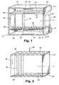
- FIG. 1 is a perspective view of the filter of the present invention illustrating the filter housing without filter sticks;
- FIG. 2 is a partial top perspective view of the filter sticks filtering section of the filter apparatus of the present invention;
- FIG. 3 is a side partial elevational view of the filter sticks filtering section of the filter apparatus of the present invention;
- FIG. 4 is a side partial elevational cut-away view of the filter apparatus of the present invention showing a security ring and a filter stick's relationship therewith;
- FIG. 5 is a top perspective view of a security ring of the filter apparatus of the present invention;
- FIG. 6 is a perspective view of a filter stick of the filter apparatus of the present invention;
- FIG. 7 is top cross-sectional view of the filter sticks filtering section and the associated filtration of polluted air in the filter apparatus of the present invention; and
- FIG. 8 is a cross-sectional side view of an oil container containing oil in the filter apparatus of the present invention.
- The present invention relates to an apparatus and method for wet filtering machine exhaust. In the preferred embodiment of the present invention, an apparatus and method for filtering the exhaust of office machines, such as copiers, printers, and facsimile machines, with oil conducted along a filter medium is disclosed. Although the present invention is described with regard to filtration of office machine exhaust, those of ordinary skill in the art will appreciate that the present invention is adaptable to variety of machines in which gas and particulate pollutants are desirably filtered from entering the ambient air.
- In the preferred embodiment, a filter apparatus of the present invention includes three main parts: (i) a housing with filter sticks; (ii) two oil containers, one for delivering oil along the filter sticks and the other for receiving the delivered oil; and (iii) a wide range of ethereal oils provided with desired scents.
- Referring to FIG. 1, a filter housing (3) of the filter apparatus of the present invention is disclosed. Preferably the housing is of rectangular shape with two side walls (62), a top wall (64), and a bottom wall (65). The housing preferably comprises heat-resistant plastic, which is able to withstand a temperature of at least 60° Celsius. Although the external appearance of the housing is preferably rectangular, the housing may be square, rectangular, round, or custom-shaped based on the exhaust opening of a machine which the filter apparatus covers.
- Adjacent to each of the upper top and bottom walls are preferably two oil container holding areas (110). Each of the holding areas preferably includes a back wall (27). A catch opening (25) is preferably provided along each of the back walls (27) for receiving a catch from the oil container. A locking projection (20) is further preferably provided along the bottom face of each of the holding areas for locking the respective oil containers in place. At the base of the upper holding area a holding area base plate (69) is provided with a plurality of housing filter stick openings (30). Similarly, the bottom holding area is enclosed by a base plate (67) with a plurality of housing filter stick openings (30).
- Each filter stick opening (30) of base plate (69) has a corresponding filter stick opening in parallel base plate (67). The filter stick's filtering section (4), the area between parallel base plates (67) and (69), preferably comprises a plurality of filter sticks (50) for conducting oil from the openings (30) in base plate (69) to the corresponding openings (30) in base plate (67).
- In each of the side walls (62) an air outflow opening (60) is provided. In order to preclude the fundamental overheating of a machine, an oblong exhaust slit is preferably located on the left and right side of the housing. The exhaust slits preferably prevent excess pressure in the filter itself, since, as a result of them, the backed up or excessively produced air quantities have the possibility of being able to exit on both sides.
- Preferably, one or more brackets (40) attach a side wall (62) to an office machine. The filter apparatus is preferably secured with filtering section (4) placed in front of the exhaust of the office machine. As a result of the different sizes of various ventilators, the exhaust openings of machines are of different sizes as well. In other words, the housing of a filter must be adjusted to the size of the exhaust openings, in order to receive the original air quantity flow of the machine. Otherwise, an overheating of the internal chamber of the machine could result.
- The attachment bracket (40) may be a single bracket or a plurality of brackets on any one or more of the walls of the housing, depending on the machine to which the filter apparatus is attached. Housing attachments, in any form, are primarily based on the respective type of machine to which the housing is to be applied. As a result, the attachment bracket contemplates a variety of attachment means, including plastic brackets and click systems.
- Preferably, in right side wall (62) an upper and lower oil container opening (70) is provided for insertion and removal of the oil containers.
- Referring to FIG. 8, an oil container (10) filled with oil (5) is disclosed. The oil container preferably includes a bottom face, a left and right face, and a front and back face. The top of the container is preferably open for filling the container with oil out of the filter housing. When placed in the filter housing, a container is either closed by top wall (64) or base plate (67), depending on whether the container is an upper or lower container. In an alternative embodiment an oil filling device may be integrated with the housing and an upper oil container without removing the container from the housing.
- The bottom face of the oil container preferably includes a plurality of oil flow openings (16). An oil pad (15) preferably covers the openings to slow and control the flow of oil (5) to the openings (16). In the preferred embodiment, the bottom third is filled by the pad (15), which is preferably a rubber foam pad.
- On the back face of the oil container, a catch (12) is preferably attached. The front face of the oil container preferably includes a grip rail (11) for sliding the oil container in and out of the filter housing. A viewing glass (13) is also preferably provided on the front face of the oil container for a user to examine the remaining oil level.
- The bottom of the oil container preferably includes one or more locking clips to secure the oil container at the locking clip projection (20) of the housing.
- Preferably, the locking clips also receive a rubber closure for closing the flow openings (16). The rubber closure preferably slides between the locking clips (14) and can be inserted or removed as needed to prevent or allow the flow of oil from the openings.
- Referring to FIGS. 1, 2, and 8 an oil container (10) filled with oil and without closure (18) is inserted through upper opening (70) into the upper container holding area (110) of the filter housing (3). The oil container catch (12) connects into catch opening (25). Locking clips (14) preferably connect to one or more locking projections (20) by a click locking system to prevent the containers from falling out. The plurality of flow openings (16) are adjacent to filter stick openings (30).
- The second oil container (10) initially does not contain oil and includes rubber closure (18) to close the plurality of flow openings (16). The second oil container is inserted into lower holding area (110) of the housing. The open top of the lower oil container is preferably adjacent to the plurality of filter stick openings in base plate (67) of the housing.
- Preferably oil (5) in the upper oil container slowly flows through the pad (15) to and through the oil flow openings (16) and into the filter stick openings (30). Gravity causes the oil to flow (90) downward along the plurality of filter sticks (50). The oil continues to flow downward to the filter stick openings (30) in base plate (67). The oil subsequently drips off into the lower oil container.
- Referring to FIG. 7 exhaust (120) from an office machine blows through the filtering section of the filter apparatus. Ozone particulates, and other pollutants contact the oil along filter sticks (50) and are removed from the exhaust. Filtered air (125) flows out of the filtering section (4) and into the ambient air from the filter apparatus.
- Referring to FIG. 6, the filters sticks (50) are preferably round, perpendicularly standing foam rubber rods of approx. 5-6 mm in diameter and a perforated plastic surface which are perpendicular and staggered to one another. In alternative embodiments the filter sticks may be of various shapes including oval, square, rectangular, triangular, and other shapes.
- The filter sticks, or foam rubber rods, are preferably a fixed component and are attached to the housing at the corresponding filter stick openings in base plates (67) and (69). The filter sticks are also preferably perpendicular in order to enable the automatic flow of oil by gravity. The filter sticks are further preferably staggered, in order to force the outflowing air quantities to flow around the foam rubber rods. The distance from one foam rubber rod to another preferably is no greater than 2 mm.
- Referring to FIGS. 4 and 5 a security ring (130) is provided in the preferred embodiment to maintain the distance between the filter sticks. The filter sticks are preferably maintained perpendicular to base plates (67) and (69), and parallel to one another.
- The foam rubber material of the filter sticks preferably prevents a rapid flow of oil from the full upper oil container into the lower empty oil container. In addition, the individual foam rubber rod is preferably mechanically strengthened internally by the perforated plastic surface (simultaneously a mechanical protection against external damage, such as during cleaning). The perforation permanently allows low moisture on the external surface of the rods. As a result of this surface moisture, microscopically small particles which are located in the exhaust flowing out of a machine by means of ventilators are preferably captured and deposited on the external cover of the foam rubber rods (the finest toner particles, oil residues, silicones, oils of all types, as well as dust and environmental air pollution).
- Referring to FIG. 2, around these filter sticks there are light channels (101) and (102) along the respective length of base plates (67) and (69). The channels prevent possible outflow of the ethereal oil during a change of the oil containers.
- In a preferred embodiment, the oil (5) is ethereal oil, which may have a desired scent. As the pollutants are removed by the oil flowing along the filter sticks, the desired scent from the ethereal oil is provided into the air by the warm air from the exhaust of an office machine. Accordingly, both filtration and a desirable scent are achieved by the filter apparatus.
- In the preferred embodiment of a method of the present invention, an oil container is filled with ethereal oil of a desirable scent and placed in the upper oil container holding area. A second, empty oil container is placed into the lower container holding area. Each of these oil containers preferably comprises heat-resistant and acid-resistant and mechanically solid plastic.
- The internal construction of each container, full or empty, is preferably the same. In order to prevent the oil which is contained in the container from being able to flow out too quickly, the lower part of the interior side of the container is designed with a foam rubber pad (along the entire length and over all openings into which the foam rubber rods lock). This foam rubber pad preferably fills approximately the lower third of the entire container and will draw the ethereal oil, but only slowly allow it to pass through to the foam rubber rods.
- In the preferred embodiment, once the upper oil container is essentially empty, and the lower container has received the flowing oil, the containers may be switched. Preferably the closure on the lower container is removed, opening the oil flow openings, and the lower container is inserted into the upper container holding area. The closure is inserted at the base of the empty upper container, thereby closing the oil openings, and the empty container is inserted into the lower holding area. Preferably, this process may be repeated for up to three months, depending on the rate of loss of the ethereal oil mixture.
- In a further embodiment, the filter sticks are preferably washable. The filter apparatus may be removed from the machine and washed with a cleansing agent, such as water, to remove the pollutants which build-up on the filter sticks.
- In an alternative embodiment, the filter housing may be discarded, and a filter apparatus with fresh filter sticks may be attached at desired filter-changing intervals for the office machine.
- Ethereal oils have very good properties for controlled flow and filtering. Preferably lime-free normal water may be added to ethereal oil to achieve desired flow rates and filtering reactions. Those of ordinary skill in the art will appreciate that the ratio of oil and water mixture is determined based on parameters such as humidity, temperature, evaporation rate, scent of oil, rate of exhaust flow, and type of filter sticks.
- While the invention has been described with reference to the structures and methods disclosed, it is not confined to the details set forth but is intended to cover such modifications or changes as may fall within the scope of the following claims.
Claims (17)
- Apparatus for wet filtering of machine exhaust (120) comprising:a filtering section (4) which is arranged between base plates (67, 69);filter sticks (50) being arranged in said filtering section (4);said filter sticks (50) are constituted of foam rubber rods; andsaid filter sticks (50) conducting oil (5) from openings (30) of said base plate (69) to openings (30) of said base plate (67) wherein gravity causes the oil (5) flowing downwards along said filter sticks.
- Apparatus according to claim 1, characterized by an upper and a lower oil container (10) wherein the upper container (10) is provided for delivering of oil (5) and the lower container (10) is provided for receiving oil (5).
- Apparatus according to claim 2, characterized in that said container (10) comprises an oil pad (15).
- Apparatus according to anyone of the claims 1 to 3, characterized in that said filter sticks (50) staggered.
- Apparatus according to anyone of the claims 1 to 4, characterized in that a distance between adjacent filter sticks (50) is no greater than 2 mm.
- Apparatus according to anyone of the claims 1 to 5, characterized in that said filter sticks (50) are strengthened internally by a perforated plastic surface.
- Apparatus according to anyone of the claims 1 to 6, characterized in that light channels (101, 102) are along the respective length of said base plates (67, 69).
- Apparatus according to anyone of the claims 2 to 7, characterized in that said upper container (10) and said lower container (10) are interchangeable.
- Apparatus according to anyone of the claims 2 to 8, characterized in that said upper container (10) comprises a foam pad (15).
- Apparatus according to anyone of the claims 1 to 9, characterized by a housing (3) including at least one auxiliary airflow opening (16).
- Method for wet filtering of machine exhaust, the method comprising the steps of:flowing of machine exhaust (120) through a filtering section (4) provided with filter sticks (50) constituted of foam rubber rods being arranged between base plates (67, 69);oil (5) flowing downward along said filter sticks (50), said flowing (90) being caused by gravity;preventing a rapid flow of said oil (5) by the foam rubber rods of said filter sticks (50);said machine exhaust (120) contacting said oil (5) along said filter sticks (50) wherein ozone particulates and other pollutants are removed from said machine exhaust (120).
- Method according to claim 11, characterized by delivering said oil (5) from an upper oil container (10) to said filter sticks (50).
- Method according to anyone of the claims 11 or 12, characterized by receiving said oil (5) from said filter sticks (50) by a lower oil container (10).
- Method according to anyone of the claims 11 to 13, characterized by use of an oil (5) comprising a scented ethereal oil.
- Method according to anyone of the claims 11 to 14, characterized by preventing from said oil (5) being contained in said container (10) flowing out too quickly by foam rubber pad (15) arranged at the interior side of said container (10).
- Method according to anyone of the claims 11 to 15, characterized by use of exhaust (120) of an office machine as machine exhaust (120).
- Method according to anyone of the claims 11 to 16, characterized in that said office machine is selected from a group consisting of a printer, a photocopier and a facsimile machine.
Applications Claiming Priority (2)
| Application Number | Priority Date | Filing Date | Title |
|---|---|---|---|
| US09/569,819 US6375717B1 (en) | 2000-05-12 | 2000-05-12 | Apparatus and method for wet filtering machine exhaust |
| PCT/US2000/013096 WO2001087460A1 (en) | 2000-05-12 | 2000-05-12 | Apparatus and method for wet filtering machine exhaust |
Publications (2)
| Publication Number | Publication Date |
|---|---|
| EP1345669A1 EP1345669A1 (en) | 2003-09-24 |
| EP1345669B1 true EP1345669B1 (en) | 2008-01-02 |
Family
ID=26680229
Family Applications (1)
| Application Number | Title | Priority Date | Filing Date |
|---|---|---|---|
| EP00935935A Expired - Lifetime EP1345669B1 (en) | 2000-05-12 | 2000-05-12 | Apparatus and method for wet filtering machine exhaust |
Country Status (10)
| Country | Link |
|---|---|
| US (1) | US6375717B1 (en) |
| EP (1) | EP1345669B1 (en) |
| JP (1) | JP2004511743A (en) |
| AT (1) | ATE382415T1 (en) |
| AU (1) | AU2000251320A1 (en) |
| CA (1) | CA2409456C (en) |
| DE (1) | DE60037683T2 (en) |
| DK (1) | DK1345669T3 (en) |
| ES (1) | ES2301484T3 (en) |
| WO (1) | WO2001087460A1 (en) |
Cited By (1)
| Publication number | Priority date | Publication date | Assignee | Title |
|---|---|---|---|---|
| RU2685347C2 (en) * | 2009-11-12 | 2019-04-17 | Новоматик Аг | Air purification device for removal of air pollutants from air trail and entertainment and/or game unit equipped with such air cleaner |
Families Citing this family (10)
| Publication number | Priority date | Publication date | Assignee | Title |
|---|---|---|---|---|
| US6726749B2 (en) * | 2000-05-12 | 2004-04-27 | Dexwet Usa, Llc | Apparatus and method for wet filtering machine exhaust |
| US6582498B1 (en) * | 2001-05-04 | 2003-06-24 | Battelle Memorial Institute | Method of separating carbon dioxide from a gas mixture using a fluid dynamic instability |
| AU2004243388B2 (en) * | 2003-05-26 | 2010-09-16 | Logos-Innovationen Gmbh | Device for the extraction of water from atmospheric air |
| EP1922129B1 (en) * | 2005-09-09 | 2012-08-29 | Dexwet Usa Llc | Filter module |
| DE102007038066A1 (en) | 2007-08-11 | 2009-02-19 | Witt, Stefan, Dipl.-Wirt. Ing. (FH) | Filter system for filtering fine dust from exhaust air during copying and printing by using e.g. color copier, has filter made of paper and textile web, and catch unit directly attaching system on fine-dust-delivering opening of device |
| KR100918429B1 (en) | 2008-01-02 | 2009-09-24 | 주식회사 카엘 | Hazardous Gas Filter |
| DE202010007120U1 (en) * | 2010-05-21 | 2011-09-07 | Novomatic Ag | Cooling air cleaner of an electronic device |
| CA2856196C (en) | 2011-12-06 | 2020-09-01 | Masco Corporation Of Indiana | Ozone distribution in a faucet |
| CN115093008B (en) | 2015-12-21 | 2024-05-14 | 德尔塔阀门公司 | Fluid delivery system including a sterilizing device |
| CN112025860A (en) * | 2020-08-27 | 2020-12-04 | 湖州南浔双林永康木盘厂 | High disconnected material protector of security for wood working |
Family Cites Families (10)
| Publication number | Priority date | Publication date | Assignee | Title |
|---|---|---|---|---|
| DE328826C (en) | 1919-06-11 | 1920-11-05 | Aeg | Process and filter for cleaning dusty gases using wet air filters |
| US1989773A (en) | 1930-06-30 | 1935-02-05 | Diamond Power Speciality | Dedusting apparatus |
| US3324630A (en) * | 1965-06-07 | 1967-06-13 | Aaron J Teller | Crossflow scrubbing process |
| BE758570A (en) * | 1970-11-06 | 1971-04-16 | Lefebvre Simon | METHOD AND APPARATUS FOR PLACING FLUIDS IN CONTACT AND TRANSFER OF MATERIAL AND HEAT BETWEEN THEM. |
| US3791102A (en) * | 1971-06-10 | 1974-02-12 | R Huntington | Multiple compartment packed bed absorber-desorber heat exchanger and method |
| US3957464A (en) * | 1974-04-25 | 1976-05-18 | Teller Environmental Systems, Inc. | Process for removing particulates from a gas |
| JPS5861815A (en) * | 1981-10-09 | 1983-04-13 | Hitachi Ltd | dust collector |
| AU7958187A (en) | 1986-10-15 | 1988-04-21 | Mitsubishi Denki Kabushiki Kaisha | Air cleaner |
| JPH11244640A (en) * | 1998-03-04 | 1999-09-14 | Tsunehiko Igarashi | Dust collector of grain drying machine and husking machine or the like as well as dust collecting bag body of dust collector of grain drying machine and husking machine or the like |
| JPH11244641A (en) * | 1998-03-05 | 1999-09-14 | Taikisha Ltd | Gas cleaning device |
-
2000
- 2000-05-12 DK DK00935935T patent/DK1345669T3/en active
- 2000-05-12 EP EP00935935A patent/EP1345669B1/en not_active Expired - Lifetime
- 2000-05-12 WO PCT/US2000/013096 patent/WO2001087460A1/en not_active Ceased
- 2000-05-12 DE DE60037683T patent/DE60037683T2/en not_active Expired - Lifetime
- 2000-05-12 US US09/569,819 patent/US6375717B1/en not_active Expired - Lifetime
- 2000-05-12 CA CA002409456A patent/CA2409456C/en not_active Expired - Fee Related
- 2000-05-12 AT AT00935935T patent/ATE382415T1/en not_active IP Right Cessation
- 2000-05-12 ES ES00935935T patent/ES2301484T3/en not_active Expired - Lifetime
- 2000-05-12 JP JP2001583913A patent/JP2004511743A/en active Pending
- 2000-05-12 AU AU2000251320A patent/AU2000251320A1/en not_active Abandoned
Cited By (1)
| Publication number | Priority date | Publication date | Assignee | Title |
|---|---|---|---|---|
| RU2685347C2 (en) * | 2009-11-12 | 2019-04-17 | Новоматик Аг | Air purification device for removal of air pollutants from air trail and entertainment and/or game unit equipped with such air cleaner |
Also Published As
| Publication number | Publication date |
|---|---|
| DK1345669T3 (en) | 2008-05-13 |
| ES2301484T3 (en) | 2008-07-01 |
| US6375717B1 (en) | 2002-04-23 |
| CA2409456C (en) | 2006-07-18 |
| WO2001087460A1 (en) | 2001-11-22 |
| EP1345669A1 (en) | 2003-09-24 |
| CA2409456A1 (en) | 2001-11-22 |
| AU2000251320A1 (en) | 2001-11-26 |
| DE60037683D1 (en) | 2008-02-14 |
| ATE382415T1 (en) | 2008-01-15 |
| JP2004511743A (en) | 2004-04-15 |
| DE60037683T2 (en) | 2009-01-02 |
Similar Documents
| Publication | Publication Date | Title |
|---|---|---|
| US6375717B1 (en) | Apparatus and method for wet filtering machine exhaust | |
| US6749672B2 (en) | Scenting device for air flow apparatus | |
| US5240487A (en) | Warm air register filter and scent dispenser | |
| US5578113A (en) | Air treatment system | |
| US6248155B1 (en) | Combination humidifier and air purifier | |
| US6923851B1 (en) | Blue smoke control collector system | |
| CA1194403A (en) | Welding fume and spark trap | |
| AU2005336321B2 (en) | Filter module | |
| JP2001259330A (en) | Air purification device and home appliance equipped with the same | |
| US10143953B1 (en) | Aroma-dispensing HVAC filter | |
| WO1995013506A1 (en) | Air cooler filter pad arrangement | |
| JP3933317B2 (en) | Filter device for electrophotographic apparatus | |
| JP3755010B2 (en) | Air purifier | |
| US6726749B2 (en) | Apparatus and method for wet filtering machine exhaust | |
| DE19953352B4 (en) | Outlet means of an ozone exhaust pipe provided in an electrophotographic image forming apparatus | |
| JP3477985B2 (en) | Air filter and its use | |
| KR100477695B1 (en) | Article and method for elimination of hydrocarbon emissions from printer exhaust | |
| US11130346B2 (en) | Combination including carbon powder replenishing bottle and carbon powder storage member | |
| KR101570148B1 (en) | Purification device for particulate in air | |
| JPH0160290B2 (en) | ||
| KR101119152B1 (en) | Water purifier for fishtank | |
| JP2000317240A (en) | Air purifying device applying water | |
| JPH11114350A (en) | Air cleaner | |
| US5015277A (en) | Integrated media cartridge and filter | |
| GB2428380A (en) | Air sterilisation apparatus |
Legal Events
| Date | Code | Title | Description |
|---|---|---|---|
| PUAI | Public reference made under article 153(3) epc to a published international application that has entered the european phase |
Free format text: ORIGINAL CODE: 0009012 |
|
| 17P | Request for examination filed |
Effective date: 20030129 |
|
| AK | Designated contracting states |
Kind code of ref document: A1 Designated state(s): AT BE CH CY DE DK ES FI FR GB GR IE IT LI LU MC NL PT SE |
|
| RAP1 | Party data changed (applicant data changed or rights of an application transferred) |
Owner name: KAILER, LUDWIG |
|
| 17Q | First examination report despatched |
Effective date: 20050401 |
|
| RAP1 | Party data changed (applicant data changed or rights of an application transferred) |
Owner name: DEXWET USA LLC |
|
| 17Q | First examination report despatched |
Effective date: 20050401 |
|
| GRAP | Despatch of communication of intention to grant a patent |
Free format text: ORIGINAL CODE: EPIDOSNIGR1 |
|
| GRAS | Grant fee paid |
Free format text: ORIGINAL CODE: EPIDOSNIGR3 |
|
| GRAA | (expected) grant |
Free format text: ORIGINAL CODE: 0009210 |
|
| AK | Designated contracting states |
Kind code of ref document: B1 Designated state(s): AT BE CH CY DE DK ES FI FR GB GR IE IT LI LU MC NL PT SE |
|
| REG | Reference to a national code |
Ref country code: GB Ref legal event code: FG4D |
|
| REG | Reference to a national code |
Ref country code: IE Ref legal event code: FG4D |
|
| REG | Reference to a national code |
Ref country code: CH Ref legal event code: EP |
|
| REF | Corresponds to: |
Ref document number: 60037683 Country of ref document: DE Date of ref document: 20080214 Kind code of ref document: P |
|
| REG | Reference to a national code |
Ref country code: SE Ref legal event code: TRGR |
|
| REG | Reference to a national code |
Ref country code: DK Ref legal event code: T3 |
|
| REG | Reference to a national code |
Ref country code: ES Ref legal event code: FG2A Ref document number: 2301484 Country of ref document: ES Kind code of ref document: T3 |
|
| REG | Reference to a national code |
Ref country code: CH Ref legal event code: NV Representative=s name: ABP PATENT NETWORK SWISS GMBH |
|
| ET | Fr: translation filed | ||
| PG25 | Lapsed in a contracting state [announced via postgrant information from national office to epo] |
Ref country code: PT Free format text: LAPSE BECAUSE OF FAILURE TO SUBMIT A TRANSLATION OF THE DESCRIPTION OR TO PAY THE FEE WITHIN THE PRESCRIBED TIME-LIMIT Effective date: 20080602 |
|
| PLBE | No opposition filed within time limit |
Free format text: ORIGINAL CODE: 0009261 |
|
| STAA | Information on the status of an ep patent application or granted ep patent |
Free format text: STATUS: NO OPPOSITION FILED WITHIN TIME LIMIT |
|
| 26N | No opposition filed |
Effective date: 20081003 |
|
| PG25 | Lapsed in a contracting state [announced via postgrant information from national office to epo] |
Ref country code: MC Free format text: LAPSE BECAUSE OF NON-PAYMENT OF DUE FEES Effective date: 20080531 |
|
| PG25 | Lapsed in a contracting state [announced via postgrant information from national office to epo] |
Ref country code: IE Free format text: LAPSE BECAUSE OF NON-PAYMENT OF DUE FEES Effective date: 20080512 |
|
| PG25 | Lapsed in a contracting state [announced via postgrant information from national office to epo] |
Ref country code: CY Free format text: LAPSE BECAUSE OF FAILURE TO SUBMIT A TRANSLATION OF THE DESCRIPTION OR TO PAY THE FEE WITHIN THE PRESCRIBED TIME-LIMIT Effective date: 20080102 |
|
| PGFP | Annual fee paid to national office [announced via postgrant information from national office to epo] |
Ref country code: NL Payment date: 20090528 Year of fee payment: 10 Ref country code: ES Payment date: 20090529 Year of fee payment: 10 |
|
| PGFP | Annual fee paid to national office [announced via postgrant information from national office to epo] |
Ref country code: FR Payment date: 20090528 Year of fee payment: 10 Ref country code: LU Payment date: 20090525 Year of fee payment: 10 Ref country code: AT Payment date: 20090529 Year of fee payment: 10 Ref country code: SE Payment date: 20090513 Year of fee payment: 10 |
|
| PGFP | Annual fee paid to national office [announced via postgrant information from national office to epo] |
Ref country code: BE Payment date: 20090528 Year of fee payment: 10 |
|
| PGFP | Annual fee paid to national office [announced via postgrant information from national office to epo] |
Ref country code: CH Payment date: 20090525 Year of fee payment: 10 |
|
| PG25 | Lapsed in a contracting state [announced via postgrant information from national office to epo] |
Ref country code: GR Free format text: LAPSE BECAUSE OF FAILURE TO SUBMIT A TRANSLATION OF THE DESCRIPTION OR TO PAY THE FEE WITHIN THE PRESCRIBED TIME-LIMIT Effective date: 20080403 |
|
| BERE | Be: lapsed |
Owner name: DEXWET USA LLC Effective date: 20100531 |
|
| REG | Reference to a national code |
Ref country code: NL Ref legal event code: V1 Effective date: 20101201 |
|
| REG | Reference to a national code |
Ref country code: CH Ref legal event code: PL |
|
| PG25 | Lapsed in a contracting state [announced via postgrant information from national office to epo] |
Ref country code: AT Free format text: LAPSE BECAUSE OF NON-PAYMENT OF DUE FEES Effective date: 20100512 |
|
| EUG | Se: european patent has lapsed | ||
| REG | Reference to a national code |
Ref country code: FR Ref legal event code: ST Effective date: 20110131 |
|
| PG25 | Lapsed in a contracting state [announced via postgrant information from national office to epo] |
Ref country code: CH Free format text: LAPSE BECAUSE OF NON-PAYMENT OF DUE FEES Effective date: 20100531 Ref country code: LI Free format text: LAPSE BECAUSE OF NON-PAYMENT OF DUE FEES Effective date: 20100531 |
|
| PG25 | Lapsed in a contracting state [announced via postgrant information from national office to epo] |
Ref country code: BE Free format text: LAPSE BECAUSE OF NON-PAYMENT OF DUE FEES Effective date: 20100531 Ref country code: NL Free format text: LAPSE BECAUSE OF NON-PAYMENT OF DUE FEES Effective date: 20101201 Ref country code: SE Free format text: LAPSE BECAUSE OF NON-PAYMENT OF DUE FEES Effective date: 20100513 |
|
| PG25 | Lapsed in a contracting state [announced via postgrant information from national office to epo] |
Ref country code: FR Free format text: LAPSE BECAUSE OF NON-PAYMENT OF DUE FEES Effective date: 20100531 |
|
| REG | Reference to a national code |
Ref country code: ES Ref legal event code: FD2A Effective date: 20110715 |
|
| PG25 | Lapsed in a contracting state [announced via postgrant information from national office to epo] |
Ref country code: ES Free format text: LAPSE BECAUSE OF NON-PAYMENT OF DUE FEES Effective date: 20110705 |
|
| PG25 | Lapsed in a contracting state [announced via postgrant information from national office to epo] |
Ref country code: ES Free format text: LAPSE BECAUSE OF NON-PAYMENT OF DUE FEES Effective date: 20100513 |
|
| PG25 | Lapsed in a contracting state [announced via postgrant information from national office to epo] |
Ref country code: LU Free format text: LAPSE BECAUSE OF NON-PAYMENT OF DUE FEES Effective date: 20100512 |
|
| PGFP | Annual fee paid to national office [announced via postgrant information from national office to epo] |
Ref country code: GB Payment date: 20140530 Year of fee payment: 15 |
|
| GBPC | Gb: european patent ceased through non-payment of renewal fee |
Effective date: 20150512 |
|
| PG25 | Lapsed in a contracting state [announced via postgrant information from national office to epo] |
Ref country code: GB Free format text: LAPSE BECAUSE OF NON-PAYMENT OF DUE FEES Effective date: 20150512 |
|
| PGFP | Annual fee paid to national office [announced via postgrant information from national office to epo] |
Ref country code: DE Payment date: 20170509 Year of fee payment: 18 Ref country code: DK Payment date: 20170510 Year of fee payment: 18 |
|
| PGFP | Annual fee paid to national office [announced via postgrant information from national office to epo] |
Ref country code: IT Payment date: 20170522 Year of fee payment: 18 Ref country code: FI Payment date: 20170509 Year of fee payment: 18 |
|
| REG | Reference to a national code |
Ref country code: DE Ref legal event code: R119 Ref document number: 60037683 Country of ref document: DE |
|
| REG | Reference to a national code |
Ref country code: DK Ref legal event code: EBP Effective date: 20180531 |
|
| PG25 | Lapsed in a contracting state [announced via postgrant information from national office to epo] |
Ref country code: FI Free format text: LAPSE BECAUSE OF NON-PAYMENT OF DUE FEES Effective date: 20180512 |
|
| PG25 | Lapsed in a contracting state [announced via postgrant information from national office to epo] |
Ref country code: DE Free format text: LAPSE BECAUSE OF NON-PAYMENT OF DUE FEES Effective date: 20181201 Ref country code: IT Free format text: LAPSE BECAUSE OF NON-PAYMENT OF DUE FEES Effective date: 20180512 |
|
| PG25 | Lapsed in a contracting state [announced via postgrant information from national office to epo] |
Ref country code: DK Free format text: LAPSE BECAUSE OF NON-PAYMENT OF DUE FEES Effective date: 20180531 |