EP1345355A2 - Apparatus and method for controlling devices in a sub-network of a home-network - Google Patents
Apparatus and method for controlling devices in a sub-network of a home-network Download PDFInfo
- Publication number
- EP1345355A2 EP1345355A2 EP03004398A EP03004398A EP1345355A2 EP 1345355 A2 EP1345355 A2 EP 1345355A2 EP 03004398 A EP03004398 A EP 03004398A EP 03004398 A EP03004398 A EP 03004398A EP 1345355 A2 EP1345355 A2 EP 1345355A2
- Authority
- EP
- European Patent Office
- Prior art keywords
- network
- sub
- information
- home
- service
- Prior art date
- Legal status (The legal status is an assumption and is not a legal conclusion. Google has not performed a legal analysis and makes no representation as to the accuracy of the status listed.)
- Withdrawn
Links
Images



Classifications
-
- H—ELECTRICITY
- H04—ELECTRIC COMMUNICATION TECHNIQUE
- H04L—TRANSMISSION OF DIGITAL INFORMATION, e.g. TELEGRAPHIC COMMUNICATION
- H04L12/00—Data switching networks
- H04L12/28—Data switching networks characterised by path configuration, e.g. LAN [Local Area Networks] or WAN [Wide Area Networks]
- H04L12/2803—Home automation networks
-
- H—ELECTRICITY
- H04—ELECTRIC COMMUNICATION TECHNIQUE
- H04L—TRANSMISSION OF DIGITAL INFORMATION, e.g. TELEGRAPHIC COMMUNICATION
- H04L12/00—Data switching networks
- H04L12/28—Data switching networks characterised by path configuration, e.g. LAN [Local Area Networks] or WAN [Wide Area Networks]
- H04L12/2803—Home automation networks
- H04L12/2816—Controlling appliance services of a home automation network by calling their functionalities
- H04L12/2818—Controlling appliance services of a home automation network by calling their functionalities from a device located outside both the home and the home network
-
- H—ELECTRICITY
- H04—ELECTRIC COMMUNICATION TECHNIQUE
- H04L—TRANSMISSION OF DIGITAL INFORMATION, e.g. TELEGRAPHIC COMMUNICATION
- H04L67/00—Network arrangements or protocols for supporting network services or applications
- H04L67/01—Protocols
- H04L67/12—Protocols specially adapted for proprietary or special-purpose networking environments, e.g. medical networks, sensor networks, networks in vehicles or remote metering networks
- H04L67/125—Protocols specially adapted for proprietary or special-purpose networking environments, e.g. medical networks, sensor networks, networks in vehicles or remote metering networks involving control of end-device applications over a network
-
- H—ELECTRICITY
- H04—ELECTRIC COMMUNICATION TECHNIQUE
- H04L—TRANSMISSION OF DIGITAL INFORMATION, e.g. TELEGRAPHIC COMMUNICATION
- H04L12/00—Data switching networks
- H04L12/28—Data switching networks characterised by path configuration, e.g. LAN [Local Area Networks] or WAN [Wide Area Networks]
- H04L12/2803—Home automation networks
- H04L12/2807—Exchanging configuration information on appliance services in a home automation network
- H04L12/281—Exchanging configuration information on appliance services in a home automation network indicating a format for calling an appliance service function in a home automation network
-
- H—ELECTRICITY
- H04—ELECTRIC COMMUNICATION TECHNIQUE
- H04L—TRANSMISSION OF DIGITAL INFORMATION, e.g. TELEGRAPHIC COMMUNICATION
- H04L12/00—Data switching networks
- H04L12/28—Data switching networks characterised by path configuration, e.g. LAN [Local Area Networks] or WAN [Wide Area Networks]
- H04L12/2803—Home automation networks
- H04L2012/284—Home automation networks characterised by the type of medium used
- H04L2012/2841—Wireless
-
- H—ELECTRICITY
- H04—ELECTRIC COMMUNICATION TECHNIQUE
- H04L—TRANSMISSION OF DIGITAL INFORMATION, e.g. TELEGRAPHIC COMMUNICATION
- H04L12/00—Data switching networks
- H04L12/28—Data switching networks characterised by path configuration, e.g. LAN [Local Area Networks] or WAN [Wide Area Networks]
- H04L12/2803—Home automation networks
- H04L2012/284—Home automation networks characterised by the type of medium used
- H04L2012/2845—Telephone line
-
- H—ELECTRICITY
- H04—ELECTRIC COMMUNICATION TECHNIQUE
- H04L—TRANSMISSION OF DIGITAL INFORMATION, e.g. TELEGRAPHIC COMMUNICATION
- H04L12/00—Data switching networks
- H04L12/28—Data switching networks characterised by path configuration, e.g. LAN [Local Area Networks] or WAN [Wide Area Networks]
- H04L12/2803—Home automation networks
- H04L2012/2847—Home automation networks characterised by the type of home appliance used
- H04L2012/2849—Audio/video appliances
Definitions
- the present invention relates to an apparatus for controlling devices in a sub-network of a home-network and a method thereof, and more particularly, to an apparatus for controlling the devices in the sub-network having a different middleware structure and a method thereof.
- the present application claims priority based on Korean Patent Application No. 2002-12986 filed on March 11, 2002, which is incorporated herein by reference.
- Domestic devices can be divided into information devices such as a personal computer, a fax machine, a scanner, and a printer, A/V devices such as a television, a set-top box, a DVD, a VCR, an audio system, a camcorder, and a domestic game system, control devices such as a coffee maker, an electric rice cooker, a refrigerator, a washing machine, a microwave oven, and a camera, and dummy devices such as a remote controller, an interphone, a sensor, and a lighting device. These devices are connected to a sub-network such as a telephone line, a wireless LAN, a blue tooth network, USB network, an IEEE1394 network, and a power line.
- A/V devices such as a television, a set-top box, a DVD, a VCR, an audio system, a camcorder, and a domestic game system
- control devices such as a coffee maker, an electric rice cooker, a refrigerator, a washing machine, a microwave oven, and a
- Fig. 1 is a drawing showing a general home-network structure.
- a telephone 120A, a notebook computer 120B, a fax machine 120C and a computer 120D are connected to a telephone line 120 and these devices form an independent network.
- a notebook computer 130A and a PDA 130B are connected to the wireless LAN or the blue tooth network 130.
- a computer 140A, a printer 140B and a scanner 140C are connected to the USB network 140.
- the IEEE1394 network 150 includes a communication protocol for A/V devices and a television 150A, a camcorder 150B and an audio system 150C are connected to it.
- control devices such as a coffee maker 160A, an electric rice cooker 160B, a refrigerator 160C, and a washing machine 160D are connected to a power line 160.
- connection devices 170 such as a bridge and comprise a home-network 100.
- a gateway 110 provides a path connecting the devices in the sub-network to the external networks.
- the conventional home-network 100 uses existing networks such as the telephone line and the power line, and new networks such as a blue tooth network and a wireless LAN together, and these devices are operated in different hardware and software platforms, it is not easy to form a home-network using a single system. Accordingly, as a method of structuring a home-network, the establishment of a common virtual computing environment, which is called a middleware, for the domestic devices and the provision of an application are suggested.
- the currently suggested middleware only provides a means of control using an independent mechanism for devices having particular common characteristics. Therefore, a unified control of the domestic devices having various characteristics is not easy.
- the present invention is developed to provide an apparatus for controlling devices in a sub-network capable of a unified control of the domestic devices having various characteristics and a method of the same by flexibly connecting devices in a sub-network of a home-network and other devices in a home-network.
- the apparatus for controlling devices in the sub-network of the home-network for achieving the above object has a message processing unit for transmitting a registration request message received from a domestic device to a master server and responding to a polling message checking whether the domestic device is in an active mode or not, an information registering unit for providing service information received from the domestic device in the sub-network and/or the updated service information to the master server, an information generating unit for generating the information on controlling and managing the domestic device in the sub-network based on the service information, in a web page format, and an information providing unit for providing the control and management information generated via a user-based interface.
- the apparatus for controlling devices in the sub-network of the home-network further comprises a command converting unit for converting a command transmitted between a domestic-network and the sub-network via a command-based interface.
- the service information includes at least one of a type of domestic device, a manufacturer, location information, a device recognition name, and a device control command list.
- the method for controlling devices in the sub-network of the home-network comprises the steps of a) providing service information on a domestic device, b) providing the service information to a master server, c) receiving a control command about a particular domestic device chosen by a user, from the master server, and d) converting the control command to a command for the particular domestic device.
- the service information is converted into an XML format and saved in a saving means.
- the service information is provided in a web page format.
- the service information includes at least one of a type of domestic device, a manufacturer, location information, a device recognition name, and a device control command list.
- Fig. 1 is a drawing showing a general home-network structure
- Fig. 2 is a drawing showing a home-network structure having an apparatus for controlling devices in a sub-network according to the present invention
- Fig. 3 is a drawing showing a protocol stack of a home-network using a middleware
- Fig. 4 is a block diagram showing the inner structure of a proxy server which is a control device of a sub-network according to the present invention
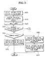
- Fig. 5 is a flow chart showing a control process of devices in a sub-network according to the present invention.
- Fig. 6 is a flow chart showing a control process of a sub-network when a service request is not input from the sub-network in the step S530 of Fig. 5.
- Fig. 2 is a drawing showing a home-network structure having an apparatus for controlling devices in a sub-network according to the present invention.
- the whole network is comprised of an external network and a home-network 260.
- the external network has an external DNS server 210 connected to the internet 230, a remote controller 1 220 and an external home-network 240. To the external home-network 240, a remote controller 2 250 is connected.
- the external DNS server 210 enables external connection to the home-network 260, as the home network 260 has a global IP address that is allocated in a uniform resource locator (URL) of the home-network 260, registered by the master server 262 of the home-network 260, and saved.
- URL uniform resource locator
- the home-network 260 comprises the master server 262, a Wide Area Network (WAN) module 264, an IEEE1394 module 266, a blue tooth module 268, a Wireless Local Area Network (WLAN) module 270, a home phoneline networking alliance (HomePNA) module 272, and an Ethernet module 273.
- WAN Wide Area Network
- WLAN Wireless Local Area Network
- HomePNA home phoneline networking alliance
- the WAN module 264, the IEEE1394 module 266, the blue tooth module 268, the WLAN module 270, the HomePNA module 272, and the Ethernet module 273 are provided with a means that receives data from devices communicating by each protocol or transmits data to relevant devices. A detailed description on these modules and a communication process between the devices connected to each module will be omitted since those skilled in the art will already have knowledge of them.
- the IP sub network 280 is comprised of an intelligent device, i.e., a local device 1 290
- the non-IP sub network 282 is comprised of a non-intelligent device, i.e., a local device 2 292 such as a dummy device.
- the dummy devices do not have self controllability and are devices such as an electric light, a door and a washing machine which operate according to simple principles. It is not shown in the drawings but the IP sub network and non-IP sub network can also be connected to other modules.
- the master server 262 is an access node enabling the home-network 260 to communicate with an external network 240 such as other home-networks and the internet 230. Therefore, in the master server 262, conversion between a private IP address allocated to the home-network device and a global IP address used in the external network, such as the internet, occurs.
- the master server 262 processes the data transmitted from or to each module. Also, the master server 262 provides information on devices through a network. In order to do that, the master server 262 manages the information on the devices inside the home-network 260 and provides information on the registered devices by replying to the request for information about the devices. In addition, as the master server 262 manages the private IP addresses allocated to the devices within the home-network 260, all nodes inside the home-network can exchange information regardless of the network media interface. Furthermore, the master server 262 enables communication between the home-network and the external device by registering the home-network and the global IP address allocated to the URL of the home-network with the external DSN server 210. The description of the master server 262 performing the function of a gateway is disclosed in the drawings and above, but the gateway can be disposed as a device separate from the master server 262.
- the master server 262 has a DNS server (not shown) and a dynamic host configuration protocol (DHCP) server (not shown).
- DNS server and the DHCP server can be disposed separately from the master server 262.
- the DNS server provides a host name to a device in the home-network 260.
- the host name of the device in the home-network 260 may be given by a user or the device may use a pre-determined default name to indicate a functional meaning of the device. When the same default name already exists, extended numbers are added.
- the host name is used to request for assignment of the private IP address of the device to the DHCP server.
- the DHCP server provides a unique identifier, i.e., a private IP address, to devices in the home-network 260.
- the proxy server 274 converts the service in the application level in order to transmit the service using the IP networking to the non-IP node.
- the proxy server 274 enables each device to have the private IP address allocated from the DHCP server for each device (hereinafter called a non-IP device) connected to the non-IP serve net 282 in order to connect the device which does not support the TCP/IP to the home network.
- the proxy server 274 is aware of the status of the non-IP node. In other words, the proxy server 274 manages the information on the status of the non-IP node whether the power is on or not, or whether it is inserted in the home-network or not. Furthermore, the proxy server 274 manages the private IP addresses having being allocated for the non-IP device and the information on the relationship between the private IP addresses of a number of non-IP devices and their hardware addresses.
- the proxy server 274 provides information on each device and control movements of a device in the non-IP sub network 282, to the remote controller 220, 250 connected to the local device 1 290 in the home-network 260 or to the internet 230, through the master server 262.
- the proxy server 272 is disposed separately from the master server 262 but it can be unified with the master server 262.
- a network having an independent structure like the non-IP sub network 282 will be called a sub-network.
- the devices in the home-network are defined as the service clients when they require connections to other devices, and are defined as the service servers when the connection is requested by other devices.
- the service server awaits a service client's request with an open access point and gets connected upon entry of the service client's request.
- the devices connected to the home-network can either be service servers or service clients according to a connection request and connection provision.
- the decision on whether the devices are to be used as service clients or service servers is made according to the operation condition of each device in the home-network. In other words, when a device is connected to the DHCP and demands allocation of a private IP address, the device becomes a service client and the DHCP becomes a service server. However, when the device provides its own operation with other device's request, the device becomes a service server.
- the interface of the service server and the service client are divided into a direct interface and an indirect interface.
- the direct interface is a service server and a service client directly providing and receiving a data unit through an IP networking pass
- the indirect interface is a service for providing and receiving a data unit through a proxy server 274 between a service server and a service client in case the service server is a non-IP node.
- Fig. 3 is a drawing showing a protocol stack of a home-network using a middleware.
- the middleware is software for communications between devices in different categories and enables communication between a number of devices.
- the middleware is located in between an operating system and an application program and transparently connects the scattered application and data in the client server environment.
- the middleware is also software independently connecting a various communication protocol, system structure, an operating system, database and an application program to hardware through the network in order to support them.
- This middleware can have a Transmission Control Protocol / Internet Protocol (TCP/IP) as a back-bone network.
- TCP/IP Transmission Control Protocol / Internet Protocol
- Fig. 4 is a block diagram showing the inner structure of a proxy server according to the present invention.
- the proxy server 274 has a message processing unit 410, an information providing unit 420, an information registering unit 430, an information generating unit 440, and a command converting unit 450.
- the message processing unit 410 transmits a request message about the service information of devices in the sub-network and replies to a polling message.
- the message processing unit 410 acts as a mediator transmitting a reply message in regard to the polling message to the master server.
- the information providing unit 420 is a structural element acting as a web server and a web browser in the proxy server 274.
- the information providing unit 420 provides user-device (U2D) base control and management service for the devices in the sub-network such as a non-IP sub network 282. Also, the information providing unit 420 requests a device to perform according to the command through the message processing unit 410 and the command converting unit 450 for performing the command received from the user connected to the proxy server 274 using a domestic web browser.
- U2D user-device
- the information registering unit 430 receives service information on the device in the sub-network, for example, a type of a device, a manufacturer, location of a device, a device recognition name in the home-network, and a device control command list, and provides the service information to the master server 262. Also, the information registering unit 430 updates service information by checking the changes of each device. Furthermore, the information registering unit 430 processes the message, i.e., service quality of the sub-network received from the message processing unit 410 or provides service information based on the request of the information providing unit 420. While the information registering unit 430, according to the preferred embodiment, is described to interface only with the message processing unit 410 and the information providing unit 420, it may also interface with other parts.
- the information generating unit 440 dynamically generates a web page about the information on the sub-network or devices in the sub-network and provides it to the information providing unit 420. "Being dynamic" means not processing data in a fixed format but processing data in a new format according to a logical basis. In order for that to occur, the information generating unit 440 uses an extensible markup language (XML) technology such as an XML parser.
- XML extensible markup language
- the command converting unit 450 performs services in connection with the devices in the sub-network.
- the process mechanism of a domestic-network and that of a sub-network are different to each other. Therefore, the command converting unit 450 converts the command-based command between the domestic-network and the sub-network.
- the proxy server 274 described above can 1) drive the devices in the sub-network to service on the basis of the Graphic User Interface (GUI) inside and outside of the home, 2) drive the devices in the sub-network to service on the command basis inside and outside of the home, 3) connect and drive the devices in the sub-network to service inside and outside of the home on the basis of the GUI, 4) connect and drive the devices in the sub-network to service inside and outside of the home on the command basis, and 5) function as a service client in the home-network on the basis of the GUI.
- GUI Graphic User Interface
- Fig. 5 is a flow chart showing the control process of the devices in the sub-network according to the present invention.
- the message processing unit 410 receives a request for registration from the devices in the sub-network and collects the service information, for example, a type of a device, a manufacturer, the location of a device, a device recognition name in the home-network, and a device control command list, included in the registration request message received from the information registering unit 430 (S500).
- the message processing unit 410 provides the service information to the master server 262 (S510), and awaits input from a user or a local device 290, 292 (S520).
- the proxy server 274 provides service according to the input path of the service request after confirming the input of the service request from the sub-network (S530).
- the service request from the sub-network is made on based on a GUI and based on a command. If the service request is made based on the GUI, the service request is input to the information providing unit 420. On the other hand, if the service request is made based on the command, the service request is input to the command converting unit 450.
- the command converting unit 450 converts the command received from the sub-network into the command of the domestic-network and sends it to the message processing unit 410, and the message processing unit 410 outputs a message instructing an operation according to the command and drives devices in the domestic-network (S550).
- the service request is based on a GUI
- the service provision will be requested from the web browser in the sub-network (S560).
- the information providing unit 420 provides a master page in the web page format or a lower page about each device (S570).
- the master server 262 provides a user with web page formatted pages provided from the information providing unit 420.
- Fig. 6 is a flow chart showing the control process of the sub-network when the service request is not input from the sub-network in step S530.
- the proxy server 274 confirms whether it is directed to the sub-network (S600). If it is confirmed that the service request has been transmitted from the inside and outside of the domestic-network to the sub-network, then it is confirmed whether the service request has been input to the message processing unit 410 (S610). A service request that has been input to the message processing unit 410 is made based on a command. In this case, the message processing unit 410 drives the devices in the sub-network according to the service request (S620).
- the service request is made based on the GUI.
- the information providing unit 420 requests the information generating unit 440 to provide information on the devices in the sub-network and the information generating unit 440 converts the device information provided from the information registering unit 430 into the web page format and provides it to the master server 262 (S630).
- the information providing unit 420 requests the performance of the service from the message processing unit 410, when it receives a request for a particular service chosen by the user reading the web page formatted information from the master server 262, and the message processing unit 410 requests for the output of a command to the command converting unit 450 for driving devices in the sub-network (S640).
- the command converting unit 450 converts the command received from the message processing unit 410 into a command suitable for the sub-network, and drives the devices in the sub-network (S650).
- the proxy server 274 operates as a service client in the domestic-network.
- a device in the domestic-network is designated to operate as a service server of the proxy server 274 (S660).
- the user confirms the service provided from the service server of the proxy server 274 and then selects a desired service (S670).
- the proxy server 274 requests the service server to provide the service selected by the user (S680).
- the series of these service providing processes are performed by the information providing unit 420.
- an apparatus for controlling devices in a sub-network according to the present invention and a home-network having a domestic-network and a sub-network in a one to one structure and a method thereof are described.
- the present invention is also applicable to a home-network having a domestic-network and a sub-network in a one to multiple structure.
- the proxy server is disposed separately in the present invention but it can also be unified with the master server.
- each different middleware device can be controlled together and continuous service of devices in the sub-network can be provided to a user in the inside and outside of the domestic-network.
Landscapes
- Engineering & Computer Science (AREA)
- Automation & Control Theory (AREA)
- Computer Networks & Wireless Communication (AREA)
- Signal Processing (AREA)
- Health & Medical Sciences (AREA)
- Computing Systems (AREA)
- General Health & Medical Sciences (AREA)
- Medical Informatics (AREA)
- Small-Scale Networks (AREA)
- Computer And Data Communications (AREA)
- Selective Calling Equipment (AREA)
Abstract
Description
Claims (9)
- An apparatus for controlling devices in a sub-network of a home-network comprising:a message processing unit for transmitting a registration request message received from a domestic device to a master server and responding to a polling message checking whether the domestic device is in an active mode or not;an information registration unit for providing at least one of service information and updated service information, received from the domestic device in the sub-network, to the master server;an information generation unit for generating control and management information for the domestic device in the sub-network, based on at least one of the service information and the updated service information; andan information providing unit for providing the control and management information.
- The apparatus according to claim 1, wherein the control and management information is in a web page format and is generated via a user-based interface.
- The apparatus according to claim 1, further comprising a command converting unit for converting a command transmitted between a domestic device and the sub-network, via a command-based interface
- The apparatus according to claim 1, wherein the service information comprises at least one of a type of domestic device, a manufacturer, location information, a device recognition name, and a device control command list.
- A method for controlling devices in a sub-network of a home-network comprising the steps of:(a) providing service information on a domestic device;(b) providing the service information to a master server;(c) receiving a control command about a particular domestic device, from the master server; and(d) converting the control command to a command for the particular domestic device.
- The method according to claim 5, wherein the particular domestic device is chosen by a user.
- The method for controlling devices according to claim 4, wherein in the step (a), the service information is converted into an extensible markup language (XML) format and saved in a saving means.
- The method for controlling devices according to claim 4, wherein in the step (b), the service information is provided in a web page format.
- The method for controlling devices according to claim 4, wherein the service information comprises at least one of a type of domestic device, a manufacturer, location information, a device recognition name, and a device control command list.
Applications Claiming Priority (2)
| Application Number | Priority Date | Filing Date | Title |
|---|---|---|---|
| KR2002012986 | 2002-03-11 | ||
| KR10-2002-0012986A KR100474485B1 (en) | 2002-03-11 | 2002-03-11 | Apparatus for controlling sub-network in home-network |
Publications (2)
| Publication Number | Publication Date |
|---|---|
| EP1345355A2 true EP1345355A2 (en) | 2003-09-17 |
| EP1345355A3 EP1345355A3 (en) | 2004-01-02 |
Family
ID=27764636
Family Applications (1)
| Application Number | Title | Priority Date | Filing Date |
|---|---|---|---|
| EP03004398A Withdrawn EP1345355A3 (en) | 2002-03-11 | 2003-03-03 | Apparatus and method for controlling devices in a sub-network of a home-network |
Country Status (5)
| Country | Link |
|---|---|
| US (1) | US20030169728A1 (en) |
| EP (1) | EP1345355A3 (en) |
| JP (1) | JP2003345687A (en) |
| KR (1) | KR100474485B1 (en) |
| CN (1) | CN1444364A (en) |
Cited By (1)
| Publication number | Priority date | Publication date | Assignee | Title |
|---|---|---|---|---|
| EP1517519A1 (en) * | 2003-09-16 | 2005-03-23 | Ricoh Company, Ltd. | Apparatus and method for proper name resolution |
Families Citing this family (109)
| Publication number | Priority date | Publication date | Assignee | Title |
|---|---|---|---|---|
| KR100474483B1 (en) * | 2002-03-12 | 2005-03-09 | 삼성전자주식회사 | Aparatus for providing device information via network and method thereof |
| KR100484804B1 (en) * | 2002-07-11 | 2005-04-22 | 엘지전자 주식회사 | Remote Control System of Home Appliances and Its Operating Method for the same. |
| KR100529876B1 (en) * | 2002-10-10 | 2005-11-22 | 엘지전자 주식회사 | Home network system's operating method |
| US6947409B2 (en) * | 2003-03-17 | 2005-09-20 | Sony Corporation | Bandwidth management of virtual networks on a shared network |
| US7283125B2 (en) * | 2003-05-09 | 2007-10-16 | Microsoft Corporation | Text input device and adapter mechanism |
| US8493326B2 (en) * | 2003-05-09 | 2013-07-23 | Microsoft Corporation | Controller with removably attachable text input device |
| JP2004341732A (en) * | 2003-05-14 | 2004-12-02 | Canon Inc | Processing device, data processing method, program and storage medium |
| US7299265B2 (en) * | 2003-06-06 | 2007-11-20 | Oracle International Corporation | Distributed computing system selecting a service master for each service by an elected global master for managing requests for that service |
| JP3809429B2 (en) * | 2003-07-25 | 2006-08-16 | キヤノン株式会社 | Management apparatus and control method thereof |
| CN1839592A (en) * | 2003-09-11 | 2006-09-27 | 富士通株式会社 | Packet relay device |
| KR101044937B1 (en) | 2003-12-01 | 2011-06-28 | 삼성전자주식회사 | Home network system and its management method |
| US7769837B2 (en) * | 2003-12-12 | 2010-08-03 | Brother Kogyo Kabushiki Kaisha | Wireless LAN setting system and communication terminal |
| KR20050060793A (en) | 2003-12-17 | 2005-06-22 | 한국전자통신연구원 | System and method for binding service between information appliances supporting in homenetwork environment |
| KR100584712B1 (en) | 2003-12-26 | 2006-05-30 | 한국전자통신연구원 | Interoperable service device between home network middleware using home gateway and OSG platform and its method |
| CN1902608A (en) * | 2004-01-06 | 2007-01-24 | 松下电器产业株式会社 | Device cooperation service system and electronic devices included in the system |
| US11811845B2 (en) | 2004-03-16 | 2023-11-07 | Icontrol Networks, Inc. | Communication protocols over internet protocol (IP) networks |
| US11277465B2 (en) | 2004-03-16 | 2022-03-15 | Icontrol Networks, Inc. | Generating risk profile using data of home monitoring and security system |
| US11201755B2 (en) | 2004-03-16 | 2021-12-14 | Icontrol Networks, Inc. | Premises system management using status signal |
| US10237237B2 (en) | 2007-06-12 | 2019-03-19 | Icontrol Networks, Inc. | Communication protocols in integrated systems |
| US10156959B2 (en) | 2005-03-16 | 2018-12-18 | Icontrol Networks, Inc. | Cross-client sensor user interface in an integrated security network |
| US11368429B2 (en) | 2004-03-16 | 2022-06-21 | Icontrol Networks, Inc. | Premises management configuration and control |
| US11159484B2 (en) | 2004-03-16 | 2021-10-26 | Icontrol Networks, Inc. | Forming a security network including integrated security system components and network devices |
| US10522026B2 (en) | 2008-08-11 | 2019-12-31 | Icontrol Networks, Inc. | Automation system user interface with three-dimensional display |
| US11316958B2 (en) | 2008-08-11 | 2022-04-26 | Icontrol Networks, Inc. | Virtual device systems and methods |
| US11343380B2 (en) | 2004-03-16 | 2022-05-24 | Icontrol Networks, Inc. | Premises system automation |
| US20090077623A1 (en) | 2005-03-16 | 2009-03-19 | Marc Baum | Security Network Integrating Security System and Network Devices |
| US8635350B2 (en) | 2006-06-12 | 2014-01-21 | Icontrol Networks, Inc. | IP device discovery systems and methods |
| US10200504B2 (en) | 2007-06-12 | 2019-02-05 | Icontrol Networks, Inc. | Communication protocols over internet protocol (IP) networks |
| US10721087B2 (en) | 2005-03-16 | 2020-07-21 | Icontrol Networks, Inc. | Method for networked touchscreen with integrated interfaces |
| US10339791B2 (en) | 2007-06-12 | 2019-07-02 | Icontrol Networks, Inc. | Security network integrated with premise security system |
| US12063220B2 (en) | 2004-03-16 | 2024-08-13 | Icontrol Networks, Inc. | Communication protocols in integrated systems |
| US11916870B2 (en) | 2004-03-16 | 2024-02-27 | Icontrol Networks, Inc. | Gateway registry methods and systems |
| US11677577B2 (en) | 2004-03-16 | 2023-06-13 | Icontrol Networks, Inc. | Premises system management using status signal |
| JP2007529826A (en) | 2004-03-16 | 2007-10-25 | アイコントロール ネットワークス, インコーポレイテッド | Object management network |
| US7711796B2 (en) | 2006-06-12 | 2010-05-04 | Icontrol Networks, Inc. | Gateway registry methods and systems |
| US11113950B2 (en) | 2005-03-16 | 2021-09-07 | Icontrol Networks, Inc. | Gateway integrated with premises security system |
| US11489812B2 (en) | 2004-03-16 | 2022-11-01 | Icontrol Networks, Inc. | Forming a security network including integrated security system components and network devices |
| US11368327B2 (en) | 2008-08-11 | 2022-06-21 | Icontrol Networks, Inc. | Integrated cloud system for premises automation |
| US20160065414A1 (en) | 2013-06-27 | 2016-03-03 | Ken Sundermeyer | Control system user interface |
| US10142392B2 (en) | 2007-01-24 | 2018-11-27 | Icontrol Networks, Inc. | Methods and systems for improved system performance |
| US11190578B2 (en) | 2008-08-11 | 2021-11-30 | Icontrol Networks, Inc. | Integrated cloud system with lightweight gateway for premises automation |
| US11582065B2 (en) | 2007-06-12 | 2023-02-14 | Icontrol Networks, Inc. | Systems and methods for device communication |
| US9729342B2 (en) | 2010-12-20 | 2017-08-08 | Icontrol Networks, Inc. | Defining and implementing sensor triggered response rules |
| US11244545B2 (en) | 2004-03-16 | 2022-02-08 | Icontrol Networks, Inc. | Cross-client sensor user interface in an integrated security network |
| US9531593B2 (en) | 2007-06-12 | 2016-12-27 | Icontrol Networks, Inc. | Takeover processes in security network integrated with premise security system |
| US9141276B2 (en) | 2005-03-16 | 2015-09-22 | Icontrol Networks, Inc. | Integrated interface for mobile device |
| KR100714687B1 (en) * | 2004-12-31 | 2007-05-04 | 삼성전자주식회사 | Apparatus and method for providing a graphical user interface composed of a plurality of columns |
| US11615697B2 (en) | 2005-03-16 | 2023-03-28 | Icontrol Networks, Inc. | Premise management systems and methods |
| US10999254B2 (en) | 2005-03-16 | 2021-05-04 | Icontrol Networks, Inc. | System for data routing in networks |
| US20110128378A1 (en) | 2005-03-16 | 2011-06-02 | Reza Raji | Modular Electronic Display Platform |
| US20120324566A1 (en) | 2005-03-16 | 2012-12-20 | Marc Baum | Takeover Processes In Security Network Integrated With Premise Security System |
| US11700142B2 (en) | 2005-03-16 | 2023-07-11 | Icontrol Networks, Inc. | Security network integrating security system and network devices |
| US9306809B2 (en) | 2007-06-12 | 2016-04-05 | Icontrol Networks, Inc. | Security system with networked touchscreen |
| US20170180198A1 (en) | 2008-08-11 | 2017-06-22 | Marc Baum | Forming a security network including integrated security system components |
| US11496568B2 (en) | 2005-03-16 | 2022-11-08 | Icontrol Networks, Inc. | Security system with networked touchscreen |
| US10079839B1 (en) | 2007-06-12 | 2018-09-18 | Icontrol Networks, Inc. | Activation of gateway device |
| US12063221B2 (en) | 2006-06-12 | 2024-08-13 | Icontrol Networks, Inc. | Activation of gateway device |
| CN101090347B (en) * | 2006-06-14 | 2011-04-20 | 华为技术有限公司 | Digital home network service operation system and its implementing method |
| KR100754222B1 (en) * | 2006-06-15 | 2007-09-03 | 삼성전자주식회사 | Service control method between network devices and network devices and storage media capable of performing the method |
| US11706279B2 (en) | 2007-01-24 | 2023-07-18 | Icontrol Networks, Inc. | Methods and systems for data communication |
| US7633385B2 (en) | 2007-02-28 | 2009-12-15 | Ucontrol, Inc. | Method and system for communicating with and controlling an alarm system from a remote server |
| JP2007193833A (en) * | 2007-03-12 | 2007-08-02 | Brother Ind Ltd | Setting processing program and setting processing device |
| US8451986B2 (en) | 2007-04-23 | 2013-05-28 | Icontrol Networks, Inc. | Method and system for automatically providing alternate network access for telecommunications |
| US11646907B2 (en) | 2007-06-12 | 2023-05-09 | Icontrol Networks, Inc. | Communication protocols in integrated systems |
| US11237714B2 (en) | 2007-06-12 | 2022-02-01 | Control Networks, Inc. | Control system user interface |
| US11089122B2 (en) | 2007-06-12 | 2021-08-10 | Icontrol Networks, Inc. | Controlling data routing among networks |
| US12003387B2 (en) | 2012-06-27 | 2024-06-04 | Comcast Cable Communications, Llc | Control system user interface |
| US11316753B2 (en) | 2007-06-12 | 2022-04-26 | Icontrol Networks, Inc. | Communication protocols in integrated systems |
| US10666523B2 (en) | 2007-06-12 | 2020-05-26 | Icontrol Networks, Inc. | Communication protocols in integrated systems |
| US11212192B2 (en) | 2007-06-12 | 2021-12-28 | Icontrol Networks, Inc. | Communication protocols in integrated systems |
| US11218878B2 (en) | 2007-06-12 | 2022-01-04 | Icontrol Networks, Inc. | Communication protocols in integrated systems |
| US10523689B2 (en) | 2007-06-12 | 2019-12-31 | Icontrol Networks, Inc. | Communication protocols over internet protocol (IP) networks |
| US11423756B2 (en) | 2007-06-12 | 2022-08-23 | Icontrol Networks, Inc. | Communication protocols in integrated systems |
| US12283172B2 (en) | 2007-06-12 | 2025-04-22 | Icontrol Networks, Inc. | Communication protocols in integrated systems |
| US11601810B2 (en) | 2007-06-12 | 2023-03-07 | Icontrol Networks, Inc. | Communication protocols in integrated systems |
| US12184443B2 (en) | 2007-06-12 | 2024-12-31 | Icontrol Networks, Inc. | Controlling data routing among networks |
| US12541237B2 (en) | 2007-08-10 | 2026-02-03 | Icontrol Networks, Inc. | Integrated security system with parallel processing architecture |
| US10223903B2 (en) | 2010-09-28 | 2019-03-05 | Icontrol Networks, Inc. | Integrated security system with parallel processing architecture |
| US11831462B2 (en) | 2007-08-24 | 2023-11-28 | Icontrol Networks, Inc. | Controlling data routing in premises management systems |
| US11916928B2 (en) | 2008-01-24 | 2024-02-27 | Icontrol Networks, Inc. | Communication protocols over internet protocol (IP) networks |
| JP5473248B2 (en) * | 2008-05-26 | 2014-04-16 | キヤノン株式会社 | Information processing apparatus, information processing apparatus control method, and computer program |
| US20170185278A1 (en) | 2008-08-11 | 2017-06-29 | Icontrol Networks, Inc. | Automation system user interface |
| US11792036B2 (en) | 2008-08-11 | 2023-10-17 | Icontrol Networks, Inc. | Mobile premises automation platform |
| US11758026B2 (en) | 2008-08-11 | 2023-09-12 | Icontrol Networks, Inc. | Virtual device systems and methods |
| US11258625B2 (en) | 2008-08-11 | 2022-02-22 | Icontrol Networks, Inc. | Mobile premises automation platform |
| US11729255B2 (en) | 2008-08-11 | 2023-08-15 | Icontrol Networks, Inc. | Integrated cloud system with lightweight gateway for premises automation |
| US8638211B2 (en) | 2009-04-30 | 2014-01-28 | Icontrol Networks, Inc. | Configurable controller and interface for home SMA, phone and multimedia |
| AU2011250886A1 (en) | 2010-05-10 | 2013-01-10 | Icontrol Networks, Inc | Control system user interface |
| US8836467B1 (en) | 2010-09-28 | 2014-09-16 | Icontrol Networks, Inc. | Method, system and apparatus for automated reporting of account and sensor zone information to a central station |
| US11750414B2 (en) | 2010-12-16 | 2023-09-05 | Icontrol Networks, Inc. | Bidirectional security sensor communication for a premises security system |
| US9147337B2 (en) | 2010-12-17 | 2015-09-29 | Icontrol Networks, Inc. | Method and system for logging security event data |
| KR101909487B1 (en) | 2011-09-30 | 2018-12-19 | 삼성전자 주식회사 | Method for registering a device to server and apparatus having the same |
| US9198204B2 (en) | 2012-04-11 | 2015-11-24 | Google Inc. | Apparatus and method for seamless commissioning of wireless devices |
| US10397013B1 (en) | 2012-04-11 | 2019-08-27 | Google Llc | User interfaces, systems and methods for configuring smart devices for interoperability with a smart hub device |
| US10075334B1 (en) | 2012-04-11 | 2018-09-11 | Google Llc | Systems and methods for commissioning a smart hub device |
| US10142122B1 (en) | 2012-04-11 | 2018-11-27 | Google Llc | User interfaces, systems and methods for configuring smart devices for interoperability with a smart hub device |
| JP6461791B2 (en) | 2012-08-07 | 2019-01-30 | フィリップス ライティング ホールディング ビー ヴィ | Timed lighting control |
| US9922580B2 (en) | 2013-04-30 | 2018-03-20 | Google Llc | Apparatus and method for the virtual demonstration of a smart phone controlled smart home using a website |
| US9413463B2 (en) | 2013-08-30 | 2016-08-09 | Google Inc. | Apparatus and method for efficient two-way optical communication where transmitter may interfere with receiver |
| KR102202660B1 (en) * | 2013-09-23 | 2021-01-13 | 삼성전자주식회사 | A method and apparatus for controlling devices for a smart home service |
| KR102213640B1 (en) * | 2013-09-23 | 2021-02-08 | 삼성전자주식회사 | Apparatus and method for exporting information related to a home device of a user device in a home network system |
| US10088818B1 (en) | 2013-12-23 | 2018-10-02 | Google Llc | Systems and methods for programming and controlling devices with sensor data and learning |
| US11146637B2 (en) | 2014-03-03 | 2021-10-12 | Icontrol Networks, Inc. | Media content management |
| US11405463B2 (en) | 2014-03-03 | 2022-08-02 | Icontrol Networks, Inc. | Media content management |
| US9544636B2 (en) | 2014-07-07 | 2017-01-10 | Google Inc. | Method and system for editing event categories |
| US10601604B2 (en) | 2014-11-12 | 2020-03-24 | Google Llc | Data processing systems and methods for smart hub devices |
| KR102478098B1 (en) * | 2015-07-31 | 2022-12-16 | 삼성전자주식회사 | Method and apparatus for controlling visitor calling in home network system |
| CN111448784B (en) | 2017-12-14 | 2022-09-06 | 索尼公司 | Information processing apparatus, information processing method, and information processing system |
| CN118540724B (en) * | 2024-07-26 | 2024-10-01 | 华为技术有限公司 | A network control method and related equipment |
Family Cites Families (13)
| Publication number | Priority date | Publication date | Assignee | Title |
|---|---|---|---|---|
| KR100209640B1 (en) * | 1996-12-26 | 1999-07-15 | 구자홍 | Apparatus for controlling home automation device by using internet |
| DE69838439T2 (en) * | 1997-06-25 | 2008-06-12 | Samsung Electronics Co., Ltd., Suwon | Method and device for monitoring devices in a home network |
| US7043532B1 (en) * | 1998-05-07 | 2006-05-09 | Samsung Electronics Co., Ltd. | Method and apparatus for universally accessible command and control information in a network |
| IL139410A0 (en) * | 1998-05-07 | 2001-11-25 | Samsung Electronics Co Ltd | Method and apparatus for universally accessible command and control information in a network |
| JP3318289B2 (en) * | 1999-08-10 | 2002-08-26 | 松下電送システム株式会社 | Home network gateway equipment |
| JP3367493B2 (en) * | 1999-12-06 | 2003-01-14 | 日本電気株式会社 | Home network system, its server, its configuration method, and recording medium on which its control program is recorded |
| US7035270B2 (en) * | 1999-12-30 | 2006-04-25 | General Instrument Corporation | Home networking gateway |
| KR100847596B1 (en) * | 2000-03-02 | 2008-07-21 | 소니 가부시끼 가이샤 | Network system, gateway, data communication method and program providing medium |
| KR20010103481A (en) * | 2000-05-10 | 2001-11-23 | 김진성 | Remote control/display system for internet home appliances |
| EP1233602A4 (en) * | 2000-09-27 | 2004-09-08 | Ntt Docomo Inc | METHOD FOR REMOTE CONTROL OF ELECTRONIC DEVICES AND INSTALLATION FOR MANAGING SUCH DEVICES |
| KR20020040959A (en) * | 2000-11-25 | 2002-05-31 | 구자홍 | Home automation method based on jini |
| KR100461593B1 (en) * | 2002-03-08 | 2004-12-14 | 삼성전자주식회사 | Apparatus and system providing remote control and management service via communication network, and method thereof |
| KR100474483B1 (en) * | 2002-03-12 | 2005-03-09 | 삼성전자주식회사 | Aparatus for providing device information via network and method thereof |
-
2002
- 2002-03-11 KR KR10-2002-0012986A patent/KR100474485B1/en not_active Expired - Fee Related
-
2003
- 2003-03-03 EP EP03004398A patent/EP1345355A3/en not_active Withdrawn
- 2003-03-04 US US10/377,745 patent/US20030169728A1/en not_active Abandoned
- 2003-03-10 CN CN03119873A patent/CN1444364A/en active Pending
- 2003-03-11 JP JP2003064939A patent/JP2003345687A/en active Pending
Cited By (2)
| Publication number | Priority date | Publication date | Assignee | Title |
|---|---|---|---|---|
| EP1517519A1 (en) * | 2003-09-16 | 2005-03-23 | Ricoh Company, Ltd. | Apparatus and method for proper name resolution |
| US7979581B2 (en) | 2003-09-16 | 2011-07-12 | Ricoh Company, Ltd. | Apparatus and method for proper name resolution |
Also Published As
| Publication number | Publication date |
|---|---|
| EP1345355A3 (en) | 2004-01-02 |
| CN1444364A (en) | 2003-09-24 |
| JP2003345687A (en) | 2003-12-05 |
| US20030169728A1 (en) | 2003-09-11 |
| KR20030073433A (en) | 2003-09-19 |
| KR100474485B1 (en) | 2005-03-09 |
Similar Documents
| Publication | Publication Date | Title |
|---|---|---|
| EP1345355A2 (en) | Apparatus and method for controlling devices in a sub-network of a home-network | |
| EP1345381B1 (en) | Apparatus and method for providing information on home network devices via internet | |
| US7292859B2 (en) | Apparatus and method for managing device information through networks | |
| US7489924B2 (en) | Apparatus and system for providing remote control service through communication network, and method thereof | |
| US7912928B2 (en) | Network device and network device control method | |
| KR100708467B1 (en) | System and method for providing service to devices in home network | |
| KR100729758B1 (en) | A method of providing services in a network system based on the Internet | |
| US20060184615A1 (en) | Service framework for home network | |
| EP1696606B1 (en) | Service framework for home network | |
| KR20050078541A (en) | Protocol for monitoring and control of home network devices | |
| KR101614548B1 (en) | Method and apparatus for preventing ip address conflict in remote access service | |
| KR100952280B1 (en) | How to remotely control rebooting of residential gateway installed in home | |
| KR20050046998A (en) | Remote controlling method and system for device in home network | |
| KR20050027500A (en) | Remote controlling method and system for device in home network |
Legal Events
| Date | Code | Title | Description |
|---|---|---|---|
| PUAI | Public reference made under article 153(3) epc to a published international application that has entered the european phase |
Free format text: ORIGINAL CODE: 0009012 |
|
| 17P | Request for examination filed |
Effective date: 20030303 |
|
| AK | Designated contracting states |
Kind code of ref document: A2 Designated state(s): AT BE BG CH CY CZ DE DK EE ES FI FR GB GR HU IE IT LI LU MC NL PT SE SI SK TR |
|
| AX | Request for extension of the european patent |
Extension state: AL LT LV MK RO |
|
| PUAL | Search report despatched |
Free format text: ORIGINAL CODE: 0009013 |
|
| AK | Designated contracting states |
Kind code of ref document: A3 Designated state(s): AT BE BG CH CY CZ DE DK EE ES FI FR GB GR HU IE IT LI LU MC NL PT SE SI SK TR |
|
| AX | Request for extension of the european patent |
Extension state: AL LT LV MK RO |
|
| RIC1 | Information provided on ipc code assigned before grant |
Ipc: 7H 04L 12/28 A |
|
| RIN1 | Information on inventor provided before grant (corrected) |
Inventor name: CHOI, MOON-JEONG,101-605 WOOSUNG APARTMENT |
|
| 17Q | First examination report despatched |
Effective date: 20040722 |
|
| AKX | Designation fees paid |
Designated state(s): DE FR GB |
|
| 17Q | First examination report despatched |
Effective date: 20040722 |
|
| GRAP | Despatch of communication of intention to grant a patent |
Free format text: ORIGINAL CODE: EPIDOSNIGR1 |
|
| STAA | Information on the status of an ep patent application or granted ep patent |
Free format text: STATUS: THE APPLICATION IS DEEMED TO BE WITHDRAWN |
|
| 18D | Application deemed to be withdrawn |
Effective date: 20080305 |