EP1345343B1 - Raman amplified dispersion compensating modules - Google Patents
Raman amplified dispersion compensating modules Download PDFInfo
- Publication number
- EP1345343B1 EP1345343B1 EP02018280A EP02018280A EP1345343B1 EP 1345343 B1 EP1345343 B1 EP 1345343B1 EP 02018280 A EP02018280 A EP 02018280A EP 02018280 A EP02018280 A EP 02018280A EP 1345343 B1 EP1345343 B1 EP 1345343B1
- Authority
- EP
- European Patent Office
- Prior art keywords
- dcf
- dispersion
- radcm
- pump
- fiber
- Prior art date
- Legal status (The legal status is an assumption and is not a legal conclusion. Google has not performed a legal analysis and makes no representation as to the accuracy of the status listed.)
- Expired - Lifetime
Links
Images




Classifications
-
- G—PHYSICS
- G02—OPTICS
- G02B—OPTICAL ELEMENTS, SYSTEMS OR APPARATUS
- G02B6/00—Light guides; Structural details of arrangements comprising light guides and other optical elements, e.g. couplings
- G02B6/24—Coupling light guides
- G02B6/26—Optical coupling means
- G02B6/28—Optical coupling means having data bus means, i.e. plural waveguides interconnected and providing an inherently bidirectional system by mixing and splitting signals
- G02B6/293—Optical coupling means having data bus means, i.e. plural waveguides interconnected and providing an inherently bidirectional system by mixing and splitting signals with wavelength selective means
- G02B6/29371—Optical coupling means having data bus means, i.e. plural waveguides interconnected and providing an inherently bidirectional system by mixing and splitting signals with wavelength selective means operating principle based on material dispersion
- G02B6/29374—Optical coupling means having data bus means, i.e. plural waveguides interconnected and providing an inherently bidirectional system by mixing and splitting signals with wavelength selective means operating principle based on material dispersion in an optical light guide
- G02B6/29376—Optical coupling means having data bus means, i.e. plural waveguides interconnected and providing an inherently bidirectional system by mixing and splitting signals with wavelength selective means operating principle based on material dispersion in an optical light guide coupling light guides for controlling wavelength dispersion, e.g. by concatenation of two light guides having different dispersion properties
-
- H—ELECTRICITY
- H04—ELECTRIC COMMUNICATION TECHNIQUE
- H04B—TRANSMISSION
- H04B10/00—Transmission systems employing electromagnetic waves other than radio-waves, e.g. infrared, visible or ultraviolet light, or employing corpuscular radiation, e.g. quantum communication
- H04B10/25—Arrangements specific to fibre transmission
- H04B10/2507—Arrangements specific to fibre transmission for the reduction or elimination of distortion or dispersion
- H04B10/2513—Arrangements specific to fibre transmission for the reduction or elimination of distortion or dispersion due to chromatic dispersion
- H04B10/2525—Arrangements specific to fibre transmission for the reduction or elimination of distortion or dispersion due to chromatic dispersion using dispersion-compensating fibres
-
- H—ELECTRICITY
- H04—ELECTRIC COMMUNICATION TECHNIQUE
- H04B—TRANSMISSION
- H04B10/00—Transmission systems employing electromagnetic waves other than radio-waves, e.g. infrared, visible or ultraviolet light, or employing corpuscular radiation, e.g. quantum communication
- H04B10/29—Repeaters
- H04B10/291—Repeaters in which processing or amplification is carried out without conversion of the main signal from optical form
- H04B10/2912—Repeaters in which processing or amplification is carried out without conversion of the main signal from optical form characterised by the medium used for amplification or processing
- H04B10/2916—Repeaters in which processing or amplification is carried out without conversion of the main signal from optical form characterised by the medium used for amplification or processing using Raman or Brillouin amplifiers
-
- H—ELECTRICITY
- H04—ELECTRIC COMMUNICATION TECHNIQUE
- H04B—TRANSMISSION
- H04B2210/00—Indexing scheme relating to optical transmission systems
- H04B2210/003—Devices including multiple stages, e.g., multi-stage optical amplifiers or dispersion compensators
Definitions
- the present invention relates to modules that compensate for chromatic dispersion of light signals when transmitted through an optical fiber.
- Dispersion compensating modules including one or more lengths of dispersion compensating fibers (DCFs), are generally known as a means for compensating for chromatic dispersion of light signals when transmitted through a fiber of a fiber optic communication system.
- DCMs thus enable existing systems to handle signals with bandwidths and wavelengths for which the systems were not originally designed, and without the need for replacing long spans of installed fiber optic cable with newer, higher rated cables. As transmission bandwidth requirements increase, the range of wavelengths over which a DCM must provide effective dispersion compensation will therefore increase accordingly.
- DCM uses more than one type of fiber in a DCM to have certain advantages, including tighter manufacturing tolerances and simultaneous control of dispersion, dispersion slope, and even higher order dispersion over a broad bandwidth (50 nm or more). Because DCMs may themselves use several kilometers of fiber having a certain signal attenuation factor, it is useful to combine the functions of dispersion compensation and Raman amplification into a single, Raman amplified, dispersion compensating module or "RADCM".
- Discrete Raman amplifiers have an advantage in that (a) they may operate in any wavelength range depending only on a supplied pump wavelength, and (b) they can achieve a broad gain-bandwidth product by using multiple pumps at several wavelengths.
- DCMs having excellent dispersion properties are not always capable of being modified into efficient RADCMs, however.
- a given DCM may provide good dispersion compensation but not be able to provide enough gain for the available Raman pump power.
- fibers used in the DCM for dispersion compensation may be too long and cause noise due to multi-pass interference (MPI), or the fibers used in the DCM for dispersion compensation may have too small an effective area and cause undesired four-wave mixing (FWM).
- MPI multi-pass interference
- FWM four-wave mixing
- EP-A-1130824 and WO 99/66607 disclose respective Raman amplified dispersion compensating modules of the kind indicated in the prior art portion of claim
- a dispersion compensation module of the kind having at least two dispersion compensating fibers to compensate for chromatic dispersion produced in light signals conducted through a transmission fiber includes a first dispersion compensating fiber (DCF) having a first length, an input end and an output end, and the first DCF has a first Raman gain coefficient (g R ( ⁇ )), a first Raman effective fiber area (A' eff ), and a first dispersion characteristic.
- DCF dispersion compensating fiber
- A' eff first Raman effective fiber area
- the module also has a second DCF having a second length, an input end and an output end, wherein the input end of the second DCF is arranged to receive light signals from the output end of the first DCF and in the absence of a pump signal source between the input end of the second DCF and the output end of the first DCF.
- the second DCF has a second Raman gain coefficient, a second Raman effective fiber area, and a second dispersion characteristic selected to cooperate with the first dispersion characteristic to produce a desired module dispersion that compensates for chromatic dispersion produced in the light signals when conducted through the transmission fiber and applied to the input end of the first DCF.
- a pump light source is coupled to either the output end of the second DCF or to the input end of the first DCF.
- the pump light source has a certain power level at one or more wavelengths to produce a desired module gain with a determined bandwidth for amplifying the light signals, and the lengths of the first and the second DCFs are selected in a manner that optimizes the module gain while maintaining the desired total module dispersion.
- RADCMs constructed according to the invention, two or more dispersion compensating fibers (DCFs) are combined to obtain simultaneous control of dispersion, relative dispersion slope (RDS) and higher order dispersion. While multiple fibers each having different dispersion characteristics may be combined in a theoretically infinite number of length combinations to achieve a desired total module dispersion for a given signal wavelength range, the Raman gain and-noise characteristics of the module may be optimized by applying one or more of the following criteria:
- the overall module gain and noise properties may be determined by solving the following coupled differential equation for each fiber, which accounts for Raman interactions between the different wavelength signals: ( Eq .
- Equation (Eq. 1) is preferably solved numerically to optimize the module performance when applied in a given communication system. Certain trends may be understood, however, for the case of a single pump and a single weak signal. In the small signal regime, the different parts of the equation may be more readily solved analytically.
- a length of fiber whose properties maximize the exponent in Eq. 2 should experience the highest pump powers. For example, for a module having two fibers with similar loss coefficients for the two fiber lengths, the longest length possible for the fiber that has the highest ratio g R /A R eff should be selected while maintaining the desired dispersion properties. Since the pump power is attenuated by fiber loss and splice loss, the fiber having the higher gain should be placed on the pump input side of the module.
- the influence of noise may modify fiber placement due to gain arguments.
- the amount of gain provided by the HNLF which has a high Raman gain coefficient and a low ratio of Rayleigh scattering to Raman gain, should be maximized. This in effect separates the functions of the HNLF, which becomes primarily a gain block, from that of one or more other DCFs that provide the bulk of dispersion compensation in the module.
- the high gain HNLF part of the module should experience the highest pump power, the low dispersion of the HNLF causes the penalty due to FWM to increase with the amount of gain provided by the HNLF.
- Counter-pumped RADCMs were constructed with the HNLF at the middle or at the signal input end, wherein the HNLF typically provided less then 3 dB out of more than 8 dB net gain. These modules showed low (-43 dB) impairment due to DRS, and FWM penalties low enough for operation at 40 Gb/s. Therefore, while placing the HNLF in the middle (or at the signal input end in a counter-pumped module) does not provide the maximum possible gain, such a configuration does allow for increased gain without significant impairment due to DRS and FWM.
- FIG. 1 represents a two-fiber RADCM 10 that was constructed according to the invention.
- the RADCM 10 has two dispersion compensating fibers (DCFs) 12, 14.
- DCFs dispersion compensating fibers
- One or more counter-pumps 16 supply pump power at one or more wavelengths to a signal output end 18 of the DCF 14.
- One or more co-pumps 20 may also supply pump power at one or more wavelengths to a signal input end 22 of the DCF 12.
- the pump wavelengths are chosen appropriately to broaden the gain-bandwidth of the module 10.
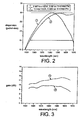
- FIG. 2 shows residual dispersion (the difference between maximum and minimum dispersion over the wavelength range of operation) when two RADCMs constructed per FIG. 1 but using different lengths for each of the DCFs 12, 14 are combined with 100 km of TWRS.
- Both of the RADCMs used HSDK and THOR8A774 for the fibers 12, 14.
- One module used 2.907 km HSDK and 2.66 km THOR8A774 (curve 1), and the other module used 1.5 km HSDK and 5.385 km THOR8A774 (curve 2).
- the residual dispersion window (FIG. 2) for the two modules is the same. As shown in FIG. 3, however, the gains of the two modules differ significantly.
- the module that used 2.9 km HSDK had as much as 3 dB more gain for a given amount of pump power than the other module.
- the overall dispersion does not depend on the order in which the fibers are configured in the module.
- the module gain does, however, depend on the placement of a given DCF in relation to pump and input signals since pump power is attenuated as it propagates through the fibers. Higher gain is thus achieved by directing the highest pump power in the fiber having the highest gain efficiency.
- FIG. 4 shows the gain of a RADCM 10 having 2.907 km of HSDK and 2.660 km of THOR8A774.
- Curve 1 shows the calculated gain when the HSDK fiber is placed near on the pump side of the RADCM
- curve 2 shows the gain when the HSDK fiber is placed on the signal side of the module.
- the gain is significantly higher (by over 1.5 dB) when the HSDK fiber, which has a higher Raman gain coefficient than the THOR8A774 fiber, is placed on the pump side of the RADCM.
- One of the DCFs 12, 14 in the RADCM 10 in FIG. 1 may have a dispersion greater than 50ps/nm-km in magnitude, and the other DCF have a dispersion less than 20ps/nm-km in magnitude but with higher gain efficiency.
- the latter fiber which is referred to herein as a highly nonlinear fiber or HNLF, does not provide appreciable dispersion compensation for the module 10 and is used to augment the gain of the first mentioned fiber.
- a HNLF has a relative dispersion slope (RDS) less than half that of a typical dispersion compensating fiber. Even more important, the relative dispersion curvature (RDC) of a HNLF should be smaller than that of a typical DCF.
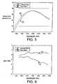
- the RADCM without the HNLF used 3.3 km of HSDK and 2.18 km of THOR8A774.
- the module that used HNLF included 2.62 km HSDK, 3.1 km THOR8A774, and 3.0 km HNLF. Because of the low RDS of the HNLF, the dispersion for the two modules as shown in FIG. 5 is nearly identical. But including the HNLF in the module significantly increased the gain as shown in FIG. 6.
- the order of fibers in the RADCM was THO8A774 on the signal input side of the module, HNLF in the middle, and HSDK on the pump side of the module. Although the mentioned ordering did not provide highest gain, it is more beneficial from a noise standpoint as discussed above. The ordering allowed for a low DRS coefficient (Rc) of -43 dB, as well as a low penalty due to FWM.
- Rc DRS coefficient
- FIG. 7 shows a RADCM 100 according to another embodiment of the invention. Components the same or similar to the RADCM 10 in FIG. 1 have corresponding reference numerals increased by 100.
- the RADCM 100 includes two or more dispersion compensating fibers 112, 114 with a pump reflector(s) in the form of a fiber Bragg grating 130 for efficient utilization of unabsorbed pump energy. Since the lengths of the DCFs 112, 114 are typically less than 10 km, significant pump power would exit the module if not reflected back by the grating 130 to improve both the gain and efficiency of the module.
- Pump reflectors such as the grating 130 in FIG. 7 may be used at the signal input end 122 of the module 100 to increase utilization of pump energy. Such an arrangement increases the module gain and lowers the penalty due to double Rayleigh scatter. Because the pump(s) 116 operates at a shorter wavelength than the light signals input to the module, the pump reflectors can be configured to introduce minimal loss (e.g., 0.1 to 0.2 dB) at the input signal wavelength. Because some fraction of the pump co-propagates with the signals, lasers for the pump 116 must be chosen so that their RIN noise falls outside the frequency range of a system receiver to prevent impairment arising from pump-signal crosstalk.
- FIG. 8 shows the effect on module gain for different numbers of pump wavelengths reflected at the signal input end 122 of the RADCM 100.
- the gain can be increased by over 3dB for some wavelengths with all the pumps reflected. Reflecting all of the pump power is not necessarily beneficial, however, because pump to pump interactions can lead to significant gain tilt.
- the optimum number of pumps to be reflected depends on the total number of pump and signal wavelengths, and power, as well as individual properties of the DCFs 112, 114 such as loss and Raman gain.
- FIG. 9 shows the gain for two RADCMs, one with 4.5 km HSDK without pump reflectors, and the other with 3.0 km HSDK and having pump reflectors. Although the gain for the two modules is similar, FIG. 10 shows that the penalty due to double Rayleigh scatter is significantly lower for the module that makes use of the shorter length of HSDK fiber and FBG pump reflectors.
- FIG. 11 is a graph showing a dispersion characteristic of a DCF as a function of wavelength. As shown in the figure, the characteristic exhibits an inflection point 200 at a certain wavelength wherein the rate of change of the slope (i.e., the second derivative) of the characteristic is substantially zero. It is preferred that one or more of the DCFs for the present module be selected such that their inflection points are at or near the operating wavelength range of the system transmission fiber (See US 2003/0174981 A1).
Landscapes
- Physics & Mathematics (AREA)
- Dispersion Chemistry (AREA)
- Engineering & Computer Science (AREA)
- Computer Networks & Wireless Communication (AREA)
- Signal Processing (AREA)
- Chemical & Material Sciences (AREA)
- Electromagnetism (AREA)
- General Physics & Mathematics (AREA)
- Optics & Photonics (AREA)
- Optical Modulation, Optical Deflection, Nonlinear Optics, Optical Demodulation, Optical Logic Elements (AREA)
- Optical Communication System (AREA)
- Lasers (AREA)
- Investigating, Analyzing Materials By Fluorescence Or Luminescence (AREA)
Description
- The present invention relates to modules that compensate for chromatic dispersion of light signals when transmitted through an optical fiber.
- Dispersion compensating modules (DCMs) including one or more lengths of dispersion compensating fibers (DCFs), are generally known as a means for compensating for chromatic dispersion of light signals when transmitted through a fiber of a fiber optic communication system. DCMs thus enable existing systems to handle signals with bandwidths and wavelengths for which the systems were not originally designed, and without the need for replacing long spans of installed fiber optic cable with newer, higher rated cables. As transmission bandwidth requirements increase, the range of wavelengths over which a DCM must provide effective dispersion compensation will therefore increase accordingly.
- The use of more than one type of fiber in a DCM has certain advantages, including tighter manufacturing tolerances and simultaneous control of dispersion, dispersion slope, and even higher order dispersion over a broad bandwidth (50 nm or more). Because DCMs may themselves use several kilometers of fiber having a certain signal attenuation factor, it is useful to combine the functions of dispersion compensation and Raman amplification into a single, Raman amplified, dispersion compensating module or "RADCM".
- As signal transmission wavelengths approach regions that cannot be handled by known rare-earth doped amplifiers, or as the transmission bandwidth exceeds that of current erbium-doped optical amplifiers, the need for a discrete amplifier with broadband gain becomes critical. Discrete Raman amplifiers have an advantage in that (a) they may operate in any wavelength range depending only on a supplied pump wavelength, and (b) they can achieve a broad gain-bandwidth product by using multiple pumps at several wavelengths.
- Existing DCMs having excellent dispersion properties are not always capable of being modified into efficient RADCMs, however. For example, a given DCM may provide good dispersion compensation but not be able to provide enough gain for the available Raman pump power. Also, fibers used in the DCM for dispersion compensation may be too long and cause noise due to multi-pass interference (MPI), or the fibers used in the DCM for dispersion compensation may have too small an effective area and cause undesired four-wave mixing (FWM).
- As mentioned, the concept of Raman pumping a single fiber DCM to compensate for signal loss is generally known. See, e.g., U.S. Patent 5,887,093 (Mar. 23, 1999). In an article by S.A.E. Lewis, et al., in 36 Elec. Lett. (2000) at page 1355, a broadband RADCM is described with two fibers whose lengths are carefully chosen together with the amount of pump power supplied to each fiber. To maintain a low noise figure, the fiber which provides the bulk of dispersion compensation is given relatively little pump power and contributes less than 25% of the gain. Notwith-standing, the predominantly compensating fiber contributes more than half of the noise. In addition, a complicated mid-span pump arrangement with multiple circulators is required. Thus, while Lewis, et al. demonstrate that Raman gain and dispersion compensation may be achieved independently, the article does not show that desired dispersion compensation and Raman gain can be achieved simultaneously, or that the DCF may achieve either wideband or slope and curvature compensation. I
- A multi-stage amplifier with the option of using DCFs is described in U.S. Patent 6,335,820 (Jan. 1, 2002). Low noise operation was achieved by the use of a mid span lossy element such as an optical isolator, and a mid-span pumping configuration, however.
- EP-A-1130824 and WO 99/66607 disclose respective Raman amplified dispersion compensating modules of the kind indicated in the prior art portion of claim
- In view of the known art, it is an object of the invention to provide a Raman amplified dispersion compensating module that provides sufficient gain, dispersion, and dispersion slope compensation with low noise due to DRS, MPI and FWM, and without the need for any complex mid-span pumping schemes or loss elements.
- This object is achieved by a Raman amplified dispersion compensating module in accordance with
claim 1. - According to the invention, a dispersion compensation module of the kind having at least two dispersion compensating fibers to compensate for chromatic dispersion produced in light signals conducted through a transmission fiber, includes a first dispersion compensating fiber (DCF) having a first length, an input end and an output end, and the first DCF has a first Raman gain coefficient (gR(λ)), a first Raman effective fiber area (A'eff), and a first dispersion characteristic. The module also has a second DCF having a second length, an input end and an output end, wherein the input end of the second DCF is arranged to receive light signals from the output end of the first DCF and in the absence of a pump signal source between the input end of the second DCF and the output end of the first DCF. The second DCF has a second Raman gain coefficient, a second Raman effective fiber area, and a second dispersion characteristic selected to cooperate with the first dispersion characteristic to produce a desired module dispersion that compensates for chromatic dispersion produced in the light signals when conducted through the transmission fiber and applied to the input end of the first DCF.
- A pump light source is coupled to either the output end of the second DCF or to the input end of the first DCF. The pump light source has a certain power level at one or more wavelengths to produce a desired module gain with a determined bandwidth for amplifying the light signals, and the lengths of the first and the second DCFs are selected in a manner that optimizes the module gain while maintaining the desired total module dispersion.
- For a better understanding of the invention, reference is made to the following description taken in conjunction with the accompanying drawing and the appended claims.
- In the drawing:
- FIG. 1 is a schematic of a first embodiment of a RADCM according to the invention;
- FIG. 2 is a graph showing residual dispersions of two RADCMs using DCFs of different lengths;
- FIG. 3 is a graph showing gain of the two RADCMs in FIG. 2;
- FIG. 4 is a graph showing gain for a RADCM in which the order of the DCFs is interchanged;
- FIG. 5 is a graph showing residual dispersion for a RADCM with and without a HNLF fiber;
- FIG. 6 is a graph showing gain for the RADCM in FIG. 5;
- FIG. 7 is a schematic of a RADCM according to a second embodiment of the invention;
- FIG. 8 is a graph showing gain as a function of a number of pumps reflected at an input end of the RADCM in FIG. 7;
- FIG. 9 is a graph showing gain of two RADCMs, one with and one without pump reflectors;
- FIG. 10 is a graph showing double Rayleigh scatter for the two RADCMs in FIG. 9; and
- FIG 11. is a graph showing dispersion of a DCF as a function of operating wavelength.
- In RADCMs constructed according to the invention, two or more dispersion compensating fibers (DCFs) are combined to obtain simultaneous control of dispersion, relative dispersion slope (RDS) and higher order dispersion. While multiple fibers each having different dispersion characteristics may be combined in a theoretically infinite number of length combinations to achieve a desired total module dispersion for a given signal wavelength range, the Raman gain and-noise characteristics of the module may be optimized by applying one or more of the following criteria:
- 1. The lengths of the DCFs in the module are chosen to maximize overall module gain while simultaneously maintaining a target dispersion.
- 2. Reflectors, such as Fiber Bragg Gratings (FBG), may be used to re-inject unabsorbed pump light at the signal input end of the RADCM to increase pump utilization while lowering noise due to double Rayleigh scatter, without significant insertion loss at the input signal wavelengths.
- 3. The lengths of one or more DCFs may be selected to introduce a dispersion greater than 50ps/nm-km in magnitude, and at least one DCF may introduce a dispersion less than 20ps/nm-km in magnitude with Aeff < 20um2(hereafter, a highly nonlinear fiber or "HNLF"). The HNLF possesses a high Raman gain coefficient, low dispersion, and low dispersion slope and curvature. The low slope and curvature of the HNLF enables the dispersion of the overall module to remain unaffected by slight alterations of the lengths of the other DCFs, and significantly increases the overall module gain.
- 4. While fiber order may not be important with respect to overall dispersion compensation provided by a RADCM, parameters including fiber loss, Raman gain, and Rayleigh scattering should be considered to optimize the fiber order for maximum Raman gain while simultaneously minimizing noise due to double Rayleigh scatter, MPI and FWM.
- In RADCMs having multiple co- and/or counter- propagating pump and signal wavelengths, and different lengths of fibers each possessing a different gain coefficient, loss and Rayleigh scattering coefficient, the overall module gain and noise properties may be determined by solving the following coupled differential equation for each fiber, which accounts for Raman interactions between the different wavelength signals:


- n f (z, v)
- forward power at frequency v at distance z;
- n τ (z, v)
- backward power at frequency v at distance z;
- α(v)
- attenuation;
- γ(v)
- Rayleigh scattering coefficient;
- g r (Δv)g r (ζ-v)
- Raman gain coefficient between frequencies ζ and v;
- A eff
- effective area of the fiber;
- h
- Planck's constant;
- k
- Boltzman's constant;
- T
- temperature of the fiber.
- The above equation (Eq. 1) is preferably solved numerically to optimize the module performance when applied in a given communication system. Certain trends may be understood, however, for the case of a single pump and a single weak signal. In the small signal regime, the different parts of the equation may be more readily solved analytically. Thus, signal power at the output of the module, Pout, for a fiber length L, is related to the signal power at the input of the amplifier, Pin, by the equation:

where gr(λ) is the Raman gain coefficient, AR eff is the Raman effective area of the fiber, PP is the input pump power in the DCF, and αs is the loss at the signal wavelength. Leff is the effective length of the fiber at the pump wavelength:
where αp is the loss at the pump wavelength. - To maximize the module gain, a length of fiber whose properties maximize the exponent in Eq. 2 should experience the highest pump powers. For example, for a module having two fibers with similar loss coefficients for the two fiber lengths, the longest length possible for the fiber that has the highest ratio gR/AR eff should be selected while maintaining the desired dispersion properties. Since the pump power is attenuated by fiber loss and splice loss, the fiber having the higher gain should be placed on the pump input side of the module.
- In the case of high gain, low dispersion fibers such as the HNLF, the influence of noise may modify fiber placement due to gain arguments. To optimize module gain while minimizing double Rayleigh scatter MPI, the amount of gain provided by the HNLF which has a high Raman gain coefficient and a low ratio of Rayleigh scattering to Raman gain, should be maximized. This in effect separates the functions of the HNLF, which becomes primarily a gain block, from that of one or more other DCFs that provide the bulk of dispersion compensation in the module. Although for maximum gain, the high gain HNLF part of the module should experience the highest pump power, the low dispersion of the HNLF causes the penalty due to FWM to increase with the amount of gain provided by the HNLF. And such impairment is greatest when the HNLF provides the largest fraction of gain in the overall module. Accordingly, for RADCMs having low noise due to MPI and FWM, a practical compromise must be reached between the amount of gain provided by the HNLF, and the amount of FWM.
- Counter-pumped RADCMs were constructed with the HNLF at the middle or at the signal input end, wherein the HNLF typically provided less then 3 dB out of more than 8 dB net gain. These modules showed low (-43 dB) impairment due to DRS, and FWM penalties low enough for operation at 40 Gb/s. Therefore, while placing the HNLF in the middle (or at the signal input end in a counter-pumped module) does not provide the maximum possible gain, such a configuration does allow for increased gain without significant impairment due to DRS and FWM.
- FIG. 1 represents a two-
fiber RADCM 10 that was constructed according to the invention. TheRADCM 10 has two dispersion compensating fibers (DCFs) 12, 14. One or more counter-pumps 16 supply pump power at one or more wavelengths to asignal output end 18 of theDCF 14. One or more co-pumps 20 may also supply pump power at one or more wavelengths to a signal input end 22 of theDCF 12. The pump wavelengths are chosen appropriately to broaden the gain-bandwidth of themodule 10. - FIG. 2 shows residual dispersion (the difference between maximum and minimum dispersion over the wavelength range of operation) when two RADCMs constructed per FIG. 1 but using different lengths for each of the
DCFs fibers - In RADCMs using two or more types of DCFs, the overall dispersion does not depend on the order in which the fibers are configured in the module. The module gain does, however, depend on the placement of a given DCF in relation to pump and input signals since pump power is attenuated as it propagates through the fibers. Higher gain is thus achieved by directing the highest pump power in the fiber having the highest gain efficiency.
- FIG. 4 shows the gain of a
RADCM 10 having 2.907 km of HSDK and 2.660 km of THOR8A774.Curve 1 shows the calculated gain when the HSDK fiber is placed near on the pump side of the RADCM, andcurve 2 shows the gain when the HSDK fiber is placed on the signal side of the module. The gain is significantly higher (by over 1.5 dB) when the HSDK fiber, which has a higher Raman gain coefficient than the THOR8A774 fiber, is placed on the pump side of the RADCM. - One of the
DCFs RADCM 10 in FIG. 1 may have a dispersion greater than 50ps/nm-km in magnitude, and the other DCF have a dispersion less than 20ps/nm-km in magnitude but with higher gain efficiency. In such case, the latter fiber which is referred to herein as a highly nonlinear fiber or HNLF, does not provide appreciable dispersion compensation for themodule 10 and is used to augment the gain of the first mentioned fiber. - Ideally, a HNLF has a relative dispersion slope (RDS) less than half that of a typical dispersion compensating fiber. Even more important, the relative dispersion curvature (RDC) of a HNLF should be smaller than that of a typical DCF.
- FIG. 5 shows the dispersion and gain of a RADCM with and without a HNLF having the properties of D = -4.9 ps/nm-km, D' = 0.017 ps/nm2-km, D" = -8.9* 10-5 ps/nm3-km. The RADCM without the HNLF used 3.3 km of HSDK and 2.18 km of THOR8A774. The module that used HNLF included 2.62 km HSDK, 3.1 km THOR8A774, and 3.0 km HNLF. Because of the low RDS of the HNLF, the dispersion for the two modules as shown in FIG. 5 is nearly identical. But including the HNLF in the module significantly increased the gain as shown in FIG. 6. The order of fibers in the RADCM was THO8A774 on the signal input side of the module, HNLF in the middle, and HSDK on the pump side of the module. Although the mentioned ordering did not provide highest gain, it is more beneficial from a noise standpoint as discussed above. The ordering allowed for a low DRS coefficient (Rc) of -43 dB, as well as a low penalty due to FWM.
- FIG. 7 shows a
RADCM 100 according to another embodiment of the invention. Components the same or similar to theRADCM 10 in FIG. 1 have corresponding reference numerals increased by 100. TheRADCM 100 includes two or moredispersion compensating fibers DCFs - Pump reflectors such as the grating 130 in FIG. 7 may be used at the
signal input end 122 of themodule 100 to increase utilization of pump energy. Such an arrangement increases the module gain and lowers the penalty due to double Rayleigh scatter. Because the pump(s) 116 operates at a shorter wavelength than the light signals input to the module, the pump reflectors can be configured to introduce minimal loss (e.g., 0.1 to 0.2 dB) at the input signal wavelength. Because some fraction of the pump co-propagates with the signals, lasers for thepump 116 must be chosen so that their RIN noise falls outside the frequency range of a system receiver to prevent impairment arising from pump-signal crosstalk. - FIG. 8 shows the effect on module gain for different numbers of pump wavelengths reflected at the
signal input end 122 of theRADCM 100. The gain can be increased by over 3dB for some wavelengths with all the pumps reflected. Reflecting all of the pump power is not necessarily beneficial, however, because pump to pump interactions can lead to significant gain tilt. The optimum number of pumps to be reflected depends on the total number of pump and signal wavelengths, and power, as well as individual properties of theDCFs - FIG. 9 shows the gain for two RADCMs, one with 4.5 km HSDK without pump reflectors, and the other with 3.0 km HSDK and having pump reflectors. Although the gain for the two modules is similar, FIG. 10 shows that the penalty due to double Rayleigh scatter is significantly lower for the module that makes use of the shorter length of HSDK fiber and FBG pump reflectors.
- FIG. 11 is a graph showing a dispersion characteristic of a DCF as a function of wavelength. As shown in the figure, the characteristic exhibits an
inflection point 200 at a certain wavelength wherein the rate of change of the slope (i.e., the second derivative) of the characteristic is substantially zero. It is preferred that one or more of the DCFs for the present module be selected such that their inflection points are at or near the operating wavelength range of the system transmission fiber (See US 2003/0174981 A1).
Claims (10)
- A Raman amplified dispersion compensation module (RADCM) (10,100) of the kind having two or more dispersion compensation fibers (DCFs) which cooperate to compensate for chromatic dispersion produced in light signals conducted through a transmission fiber, comprising:a first DCF (12, 112) having a first length, an input end (22, 122) and an output end (24, 124), and the first DCF has a first Raman gain coefficient (gR(λ)), a first Raman effective fiber area (AR eff), and a first dispersion characteristic;a second DCF (14, 114) having a second length, an input end (26, 126) and an output end (18, 118), wherein the input end of the second DCF is arranged to receive light signals from the output end of the first DCF in the absence of a pump signal source between the input end of the second DCF and the output end of the first DCF, and the second DCF has a second Raman gain coefficient, a second Raman effective fiber area, and a second dispersion characteristic selected to cooperate with the first dispersion characteristic so that compensated light signals will be provided at the output end of the second DCF: anda pump light source (16, 20, 116) coupled to either the output end (18, 118) of the second DCF or to the input end (22, 122) of the first DCF, wherein the pump light source has a certain power level at one or more wavelengths for producing a desired module gain with a determined bandwidth for amplifying light signals to be compensated;characterized in that:the length (L) of the DCF having the highest value of [(gR(λ)/AR eff)(PP)(Leff)-(αs)(L)] is substantially as great as possible while maintaining the desired total module dispersion, wherein PP is pump power input to the DCF, αs is the DCF loss at the transmission signal wavelength, and Leff is the effective length of the DCF at the wavelength of the pump light wherein Leff = (1/αP)(1-e-a P L) and αP is the DCF loss at the pump light wavelength, and gR (λ) is the Raman gain coefficient.
- A RADCM according to claim 1, wherein the pump light source (16, 116) is coupled to the output end (18, 118) of the second DCF (14, 114), and including one or more pump reflectors (130) arranged at the input end (22, 122) of the first DCF (12, 112).
- A RADCM according to claim 2, wherein one or more of the pump reflectors is a fiber Bragg grating (130).
- A RADCM according to claim 1, including a third DCF having an input end arranged to receive light signals from the output end (24, 124) of the first DCF (12, 112), and an output end arranged to provide the light signals received at the input end of the third DCF to the input end (26, 126) of the second DCF.
- A RADCM according to claim 1, wherein one of the DCFs has a dispersion less than about 20 ps/nm-km, and an effective area less than about 20µm2.
- A RADCM according to claim 5, wherein one of the DCFs has a dispersion greater than about 50 ps/nm-km.
- A RADCM according to claim 1, wherein at least one of the DCFs has a dispersion characteristic with an inflection point (200; FIG. 11) at a wavelength that is within or near an operating bandwidth of a transmission fiber to be compensated by the module.
- A RADCM according to claim 5, wherein the one DCF has a dispersion of less than 10 ps/nm-km, and at least one other DCF is arranged between the one DCF and the pump light source.
- An optical fiber communication system comprising a transmitter for launching a light signal, a system transmission fiber for transmitting the light signal over a desired path, a receiver for receiving the light signal, and a RADCM according to claim 1 operatively coupled to the transmission fiber between the transmitter and the receiver to compensate for chromatic dispersion produced in the light signal by the transmission fiber.
- A RADCM according to claim 4, wherein one or more pump light signals supplied to the first DCF (12, 112), the third DCF and the second DCF (14, 114), originate from the pump light source (16, 20, 116) coupled to either the output end (18, 118) of the second DCF or to the input end (22, 122) of the first DCF and in the absence of a mid span pumping arrangement.
Applications Claiming Priority (2)
| Application Number | Priority Date | Filing Date | Title |
|---|---|---|---|
| US10/099,820 US6504973B1 (en) | 2002-03-16 | 2002-03-16 | Raman amplified dispersion compensating modules |
| US99820 | 2002-03-16 |
Publications (3)
| Publication Number | Publication Date |
|---|---|
| EP1345343A2 EP1345343A2 (en) | 2003-09-17 |
| EP1345343A3 EP1345343A3 (en) | 2005-04-06 |
| EP1345343B1 true EP1345343B1 (en) | 2006-05-31 |
Family
ID=22276776
Family Applications (1)
| Application Number | Title | Priority Date | Filing Date |
|---|---|---|---|
| EP02018280A Expired - Lifetime EP1345343B1 (en) | 2002-03-16 | 2002-08-22 | Raman amplified dispersion compensating modules |
Country Status (5)
| Country | Link |
|---|---|
| US (1) | US6504973B1 (en) |
| EP (1) | EP1345343B1 (en) |
| JP (1) | JP3934517B2 (en) |
| CN (1) | CN1306733C (en) |
| DE (1) | DE60211848T2 (en) |
Families Citing this family (12)
| Publication number | Priority date | Publication date | Assignee | Title |
|---|---|---|---|---|
| US6577789B1 (en) * | 2001-09-26 | 2003-06-10 | Onetta, Inc. | Double-pass optical amplifiers and optical network equipment |
| US7295584B2 (en) * | 2001-12-17 | 2007-11-13 | Peleton Photonic Systems | System and method for generating multi-wavelength laser source using highly nonlinear fiber |
| JP2003262745A (en) * | 2002-03-07 | 2003-09-19 | Sumitomo Electric Ind Ltd | Fiber module for dispersion compensation, dispersion compensation module, and optical communication system |
| US6965738B2 (en) * | 2002-04-16 | 2005-11-15 | Eiselt Michael H | Chromatic dispersion compensation system and method |
| US7460745B2 (en) * | 2002-06-04 | 2008-12-02 | Pivotal Decisions Llc | Configurable dispersion compensation trimmer |
| US6865303B2 (en) * | 2002-06-24 | 2005-03-08 | Avanex Corporation | Method and apparatus for reducing multi-path interference in dispersion compensation systems |
| JP4113761B2 (en) * | 2002-11-05 | 2008-07-09 | 富士通株式会社 | Optical amplifier |
| FR2854516B1 (en) * | 2003-04-29 | 2005-07-22 | Cit Alcatel | CHROMATIC DISPERSION COMPENSATION MODULE |
| KR100668284B1 (en) * | 2004-12-14 | 2007-01-16 | 한국전자통신연구원 | Distributed Compensation Fiber for S-band Isolated Raman Amplifier |
| US8228598B2 (en) * | 2008-01-07 | 2012-07-24 | Xtera Communications, Inc. | Optical amplifier with Raman and rare-earth-doped fiber amplifier both pumped efficiently using direct and reflected pump light |
| US8594502B2 (en) * | 2009-04-15 | 2013-11-26 | Ofs Fitel, Llc | Method and apparatus using distributed raman amplification and remote pumping in bidirectional optical communication networks |
| JP5353582B2 (en) * | 2009-09-10 | 2013-11-27 | 富士通株式会社 | Optical amplifier |
Family Cites Families (10)
| Publication number | Priority date | Publication date | Assignee | Title |
|---|---|---|---|---|
| US4616898A (en) * | 1980-03-31 | 1986-10-14 | Polaroid Corporation | Optical communication systems using raman repeaters and components therefor |
| EP0186299B1 (en) * | 1984-12-13 | 1990-04-18 | Stc Plc | Optical amplifier |
| US4685107A (en) * | 1986-06-09 | 1987-08-04 | Spectra-Physics, Inc. | Dispersion compensated fiber Raman oscillator |
| US5361319A (en) * | 1992-02-04 | 1994-11-01 | Corning Incorporated | Dispersion compensating devices and systems |
| JP3396270B2 (en) * | 1993-08-10 | 2003-04-14 | 富士通株式会社 | Optical dispersion compensation method |
| US5887093A (en) * | 1997-09-12 | 1999-03-23 | Lucent Technologies Incorporated | Optical fiber dispersion compensation |
| US6335820B1 (en) * | 1999-12-23 | 2002-01-01 | Xtera Communications, Inc. | Multi-stage optical amplifier and broadband communication system |
| ATE488037T1 (en) * | 1998-06-16 | 2010-11-15 | Xtera Communications Inc | DISPERSION COMPENSATING AND Amplifying OPTICAL ELEMENT |
| JP2001237777A (en) * | 2000-02-25 | 2001-08-31 | Kddi Corp | Optical transmission path |
| JP2001308790A (en) * | 2000-04-19 | 2001-11-02 | Kdd Submarine Cable Systems Inc | Optical transmission system and optical transmission path |
-
2002
- 2002-03-16 US US10/099,820 patent/US6504973B1/en not_active Expired - Lifetime
- 2002-08-22 DE DE60211848T patent/DE60211848T2/en not_active Expired - Lifetime
- 2002-08-22 EP EP02018280A patent/EP1345343B1/en not_active Expired - Lifetime
- 2002-09-18 CN CNB021428468A patent/CN1306733C/en not_active Expired - Fee Related
- 2002-09-20 JP JP2002274646A patent/JP3934517B2/en not_active Expired - Fee Related
Also Published As
| Publication number | Publication date |
|---|---|
| JP2003289285A (en) | 2003-10-10 |
| JP3934517B2 (en) | 2007-06-20 |
| CN1445939A (en) | 2003-10-01 |
| EP1345343A2 (en) | 2003-09-17 |
| CN1306733C (en) | 2007-03-21 |
| EP1345343A3 (en) | 2005-04-06 |
| DE60211848D1 (en) | 2006-07-06 |
| DE60211848T2 (en) | 2006-12-21 |
| US6504973B1 (en) | 2003-01-07 |
Similar Documents
| Publication | Publication Date | Title |
|---|---|---|
| US6359725B1 (en) | Multi-stage optical amplifier and broadband communication system | |
| US6335820B1 (en) | Multi-stage optical amplifier and broadband communication system | |
| US6631025B2 (en) | Low-noise distributed Raman amplifier using bi-directional pumping using multiple Raman orders | |
| US6574037B2 (en) | All band amplifier | |
| US20030035202A1 (en) | Active gain equalization | |
| US6760148B2 (en) | Nonlinear polarization amplifiers in nonzero dispersion shifted fiber | |
| US6943936B2 (en) | Co-propagating Raman amplifiers | |
| EP1176742B1 (en) | Raman amplifier module and optical transmission system using the same | |
| US6504973B1 (en) | Raman amplified dispersion compensating modules | |
| US6304691B1 (en) | Wavelength division multiplexed optical communication system having reduced short wavelength loss | |
| US20040240043A1 (en) | Optical fiber amplifier | |
| US6924926B2 (en) | Laser diode pump sources | |
| EP1372276A2 (en) | Raman optical fiber amplifier using Erbium doped fiber | |
| US20020067537A1 (en) | Dispersion compensating nonlinear polarization amplifiers | |
| US20050259315A1 (en) | Cascaded raman pump for raman amplification in optical systems | |
| US20030169986A1 (en) | Optical fiber, optical component, dispersion compensating fiber module, and optical communication system | |
| WO2001047152A2 (en) | A lossless optical transmission link with raman gain | |
| EP1410537A2 (en) | System and method of dispersion compensation in optical communication systems | |
| Chen et al. | Maximum-channel-number Investigation of Limiting-Amplified Multiwavelength Dispersion Compensator Incorporating Chirped Fiber Gratings |
Legal Events
| Date | Code | Title | Description |
|---|---|---|---|
| PUAI | Public reference made under article 153(3) epc to a published international application that has entered the european phase |
Free format text: ORIGINAL CODE: 0009012 |
|
| 17P | Request for examination filed |
Effective date: 20020822 |
|
| AK | Designated contracting states |
Kind code of ref document: A2 Designated state(s): AT BE BG CH CY CZ DE DK EE ES FI FR GB GR IE IT LI LU MC NL PT SE SK TR |
|
| AX | Request for extension of the european patent |
Extension state: AL LT LV MK RO SI |
|
| PUAL | Search report despatched |
Free format text: ORIGINAL CODE: 0009013 |
|
| AK | Designated contracting states |
Kind code of ref document: A3 Designated state(s): AT BE BG CH CY CZ DE DK EE ES FI FR GB GR IE IT LI LU MC NL PT SE SK TR |
|
| AX | Request for extension of the european patent |
Extension state: AL LT LV MK RO SI |
|
| RIC1 | Information provided on ipc code assigned before grant |
Ipc: 7H 04B 10/18 B Ipc: 7G 02B 6/16 B Ipc: 7H 04B 10/17 A |
|
| 17Q | First examination report despatched |
Effective date: 20050405 |
|
| GRAP | Despatch of communication of intention to grant a patent |
Free format text: ORIGINAL CODE: EPIDOSNIGR1 |
|
| AKX | Designation fees paid |
Designated state(s): DE FR GB |
|
| RIC1 | Information provided on ipc code assigned before grant |
Ipc: G02B 6/16 19850101AFI20051117BHEP |
|
| GRAS | Grant fee paid |
Free format text: ORIGINAL CODE: EPIDOSNIGR3 |
|
| GRAA | (expected) grant |
Free format text: ORIGINAL CODE: 0009210 |
|
| AK | Designated contracting states |
Kind code of ref document: B1 Designated state(s): DE FR GB |
|
| REG | Reference to a national code |
Ref country code: GB Ref legal event code: FG4D |
|
| RIC1 | Information provided on ipc code assigned before grant |
Ipc: G02B 6/02 20060101AFI20060410BHEP |
|
| REF | Corresponds to: |
Ref document number: 60211848 Country of ref document: DE Date of ref document: 20060706 Kind code of ref document: P |
|
| ET | Fr: translation filed | ||
| PLBE | No opposition filed within time limit |
Free format text: ORIGINAL CODE: 0009261 |
|
| STAA | Information on the status of an ep patent application or granted ep patent |
Free format text: STATUS: NO OPPOSITION FILED WITHIN TIME LIMIT |
|
| 26N | No opposition filed |
Effective date: 20070301 |
|
| PGFP | Annual fee paid to national office [announced via postgrant information from national office to epo] |
Ref country code: DE Payment date: 20140827 Year of fee payment: 13 |
|
| PGFP | Annual fee paid to national office [announced via postgrant information from national office to epo] |
Ref country code: FR Payment date: 20140818 Year of fee payment: 13 Ref country code: GB Payment date: 20140827 Year of fee payment: 13 |
|
| REG | Reference to a national code |
Ref country code: DE Ref legal event code: R119 Ref document number: 60211848 Country of ref document: DE |
|
| GBPC | Gb: european patent ceased through non-payment of renewal fee |
Effective date: 20150822 |
|
| REG | Reference to a national code |
Ref country code: FR Ref legal event code: ST Effective date: 20160429 |
|
| PG25 | Lapsed in a contracting state [announced via postgrant information from national office to epo] |
Ref country code: GB Free format text: LAPSE BECAUSE OF NON-PAYMENT OF DUE FEES Effective date: 20150822 Ref country code: DE Free format text: LAPSE BECAUSE OF NON-PAYMENT OF DUE FEES Effective date: 20160301 |
|
| PG25 | Lapsed in a contracting state [announced via postgrant information from national office to epo] |
Ref country code: FR Free format text: LAPSE BECAUSE OF NON-PAYMENT OF DUE FEES Effective date: 20150831 |