EP1345045A1 - Method for detecting stationary object on road - Google Patents
Method for detecting stationary object on road Download PDFInfo
- Publication number
- EP1345045A1 EP1345045A1 EP01271549A EP01271549A EP1345045A1 EP 1345045 A1 EP1345045 A1 EP 1345045A1 EP 01271549 A EP01271549 A EP 01271549A EP 01271549 A EP01271549 A EP 01271549A EP 1345045 A1 EP1345045 A1 EP 1345045A1
- Authority
- EP
- European Patent Office
- Prior art keywords
- target
- camera
- road
- radar
- captured
- Prior art date
- Legal status (The legal status is an assumption and is not a legal conclusion. Google has not performed a legal analysis and makes no representation as to the accuracy of the status listed.)
- Withdrawn
Links
Images




Classifications
-
- G—PHYSICS
- G01—MEASURING; TESTING
- G01J—MEASUREMENT OF INTENSITY, VELOCITY, SPECTRAL CONTENT, POLARISATION, PHASE OR PULSE CHARACTERISTICS OF INFRARED, VISIBLE OR ULTRAVIOLET LIGHT; COLORIMETRY; RADIATION PYROMETRY
- G01J1/00—Photometry, e.g. photographic exposure meter
-
- G—PHYSICS
- G01—MEASURING; TESTING
- G01S—RADIO DIRECTION-FINDING; RADIO NAVIGATION; DETERMINING DISTANCE OR VELOCITY BY USE OF RADIO WAVES; LOCATING OR PRESENCE-DETECTING BY USE OF THE REFLECTION OR RERADIATION OF RADIO WAVES; ANALOGOUS ARRANGEMENTS USING OTHER WAVES
- G01S7/00—Details of systems according to groups G01S13/00, G01S15/00, G01S17/00
- G01S7/02—Details of systems according to groups G01S13/00, G01S15/00, G01S17/00 of systems according to group G01S13/00
- G01S7/41—Details of systems according to groups G01S13/00, G01S15/00, G01S17/00 of systems according to group G01S13/00 using analysis of echo signal for target characterisation; Target signature; Target cross-section
- G01S7/411—Identification of targets based on measurements of radar reflectivity
- G01S7/412—Identification of targets based on measurements of radar reflectivity based on a comparison between measured values and known or stored values
-
- G—PHYSICS
- G01—MEASURING; TESTING
- G01S—RADIO DIRECTION-FINDING; RADIO NAVIGATION; DETERMINING DISTANCE OR VELOCITY BY USE OF RADIO WAVES; LOCATING OR PRESENCE-DETECTING BY USE OF THE REFLECTION OR RERADIATION OF RADIO WAVES; ANALOGOUS ARRANGEMENTS USING OTHER WAVES
- G01S13/00—Systems using the reflection or reradiation of radio waves, e.g. radar systems; Analogous systems using reflection or reradiation of waves whose nature or wavelength is irrelevant or unspecified
- G01S13/86—Combinations of radar systems with non-radar systems, e.g. sonar, direction finder
- G01S13/867—Combination of radar systems with cameras
-
- G—PHYSICS
- G01—MEASURING; TESTING
- G01S—RADIO DIRECTION-FINDING; RADIO NAVIGATION; DETERMINING DISTANCE OR VELOCITY BY USE OF RADIO WAVES; LOCATING OR PRESENCE-DETECTING BY USE OF THE REFLECTION OR RERADIATION OF RADIO WAVES; ANALOGOUS ARRANGEMENTS USING OTHER WAVES
- G01S13/00—Systems using the reflection or reradiation of radio waves, e.g. radar systems; Analogous systems using reflection or reradiation of waves whose nature or wavelength is irrelevant or unspecified
- G01S13/88—Radar or analogous systems specially adapted for specific applications
- G01S13/93—Radar or analogous systems specially adapted for specific applications for anti-collision purposes
- G01S13/931—Radar or analogous systems specially adapted for specific applications for anti-collision purposes of land vehicles
-
- G—PHYSICS
- G06—COMPUTING OR CALCULATING; COUNTING
- G06F—ELECTRIC DIGITAL DATA PROCESSING
- G06F18/00—Pattern recognition
- G06F18/20—Analysing
- G06F18/25—Fusion techniques
- G06F18/254—Fusion techniques of classification results, e.g. of results related to same input data
- G06F18/256—Fusion techniques of classification results, e.g. of results related to same input data of results relating to different input data, e.g. multimodal recognition
-
- G—PHYSICS
- G06—COMPUTING OR CALCULATING; COUNTING
- G06V—IMAGE OR VIDEO RECOGNITION OR UNDERSTANDING
- G06V10/00—Arrangements for image or video recognition or understanding
- G06V10/20—Image preprocessing
- G06V10/255—Detecting or recognising potential candidate objects based on visual cues, e.g. shapes
-
- G—PHYSICS
- G06—COMPUTING OR CALCULATING; COUNTING
- G06V—IMAGE OR VIDEO RECOGNITION OR UNDERSTANDING
- G06V10/00—Arrangements for image or video recognition or understanding
- G06V10/70—Arrangements for image or video recognition or understanding using pattern recognition or machine learning
- G06V10/77—Processing image or video features in feature spaces; using data integration or data reduction, e.g. principal component analysis [PCA] or independent component analysis [ICA] or self-organising maps [SOM]; Blind source separation
- G06V10/80—Fusion, i.e. combining data from various sources at the sensor level, preprocessing level, feature extraction level or classification level
- G06V10/809—Fusion, i.e. combining data from various sources at the sensor level, preprocessing level, feature extraction level or classification level of classification results, e.g. where the classifiers operate on the same input data
- G06V10/811—Fusion, i.e. combining data from various sources at the sensor level, preprocessing level, feature extraction level or classification level of classification results, e.g. where the classifiers operate on the same input data the classifiers operating on different input data, e.g. multi-modal recognition
-
- G—PHYSICS
- G01—MEASURING; TESTING
- G01S—RADIO DIRECTION-FINDING; RADIO NAVIGATION; DETERMINING DISTANCE OR VELOCITY BY USE OF RADIO WAVES; LOCATING OR PRESENCE-DETECTING BY USE OF THE REFLECTION OR RERADIATION OF RADIO WAVES; ANALOGOUS ARRANGEMENTS USING OTHER WAVES
- G01S13/00—Systems using the reflection or reradiation of radio waves, e.g. radar systems; Analogous systems using reflection or reradiation of waves whose nature or wavelength is irrelevant or unspecified
- G01S13/88—Radar or analogous systems specially adapted for specific applications
- G01S13/93—Radar or analogous systems specially adapted for specific applications for anti-collision purposes
- G01S13/931—Radar or analogous systems specially adapted for specific applications for anti-collision purposes of land vehicles
- G01S2013/9318—Controlling the steering
-
- G—PHYSICS
- G01—MEASURING; TESTING
- G01S—RADIO DIRECTION-FINDING; RADIO NAVIGATION; DETERMINING DISTANCE OR VELOCITY BY USE OF RADIO WAVES; LOCATING OR PRESENCE-DETECTING BY USE OF THE REFLECTION OR RERADIATION OF RADIO WAVES; ANALOGOUS ARRANGEMENTS USING OTHER WAVES
- G01S13/00—Systems using the reflection or reradiation of radio waves, e.g. radar systems; Analogous systems using reflection or reradiation of waves whose nature or wavelength is irrelevant or unspecified
- G01S13/88—Radar or analogous systems specially adapted for specific applications
- G01S13/93—Radar or analogous systems specially adapted for specific applications for anti-collision purposes
- G01S13/931—Radar or analogous systems specially adapted for specific applications for anti-collision purposes of land vehicles
- G01S2013/93185—Controlling the brakes
-
- G—PHYSICS
- G01—MEASURING; TESTING
- G01S—RADIO DIRECTION-FINDING; RADIO NAVIGATION; DETERMINING DISTANCE OR VELOCITY BY USE OF RADIO WAVES; LOCATING OR PRESENCE-DETECTING BY USE OF THE REFLECTION OR RERADIATION OF RADIO WAVES; ANALOGOUS ARRANGEMENTS USING OTHER WAVES
- G01S13/00—Systems using the reflection or reradiation of radio waves, e.g. radar systems; Analogous systems using reflection or reradiation of waves whose nature or wavelength is irrelevant or unspecified
- G01S13/88—Radar or analogous systems specially adapted for specific applications
- G01S13/93—Radar or analogous systems specially adapted for specific applications for anti-collision purposes
- G01S13/931—Radar or analogous systems specially adapted for specific applications for anti-collision purposes of land vehicles
- G01S2013/9319—Controlling the accelerator
-
- G—PHYSICS
- G01—MEASURING; TESTING
- G01S—RADIO DIRECTION-FINDING; RADIO NAVIGATION; DETERMINING DISTANCE OR VELOCITY BY USE OF RADIO WAVES; LOCATING OR PRESENCE-DETECTING BY USE OF THE REFLECTION OR RERADIATION OF RADIO WAVES; ANALOGOUS ARRANGEMENTS USING OTHER WAVES
- G01S13/00—Systems using the reflection or reradiation of radio waves, e.g. radar systems; Analogous systems using reflection or reradiation of waves whose nature or wavelength is irrelevant or unspecified
- G01S13/88—Radar or analogous systems specially adapted for specific applications
- G01S13/93—Radar or analogous systems specially adapted for specific applications for anti-collision purposes
- G01S13/931—Radar or analogous systems specially adapted for specific applications for anti-collision purposes of land vehicles
- G01S2013/9327—Sensor installation details
- G01S2013/93271—Sensor installation details in the front of the vehicles
Definitions
- the present invention relates to a method for detecting a stationary object located above a road, in particular, an overhead structure such as a bridge over a road, by using radar detection in combination with camera image processing.
- a scanning radar scans a radar beam by moving the beam from left to right or from right to left at very small step angles within a predetermined time. At each step angle, the radar beam is projected from the radar-equipped vehicle toward a vehicle traveling in front, and the reflected wave from the vehicle in front is received and processed to detect the presence of the vehicle in front and compute the distance and relative velocity with respect to that vehicle.
- the method uses a camera and a radar system, and when it is determined that the target captured by the camera is the same target that has been captured by the radar, and when it is determined from an image captured by the camera that the target is at a height higher than the horison level, the method determines that the target is a stationary object located above the road.
- the method determines that the target is a stationary object located above the road.
- the method determines that the target is a stationary object located above the road.
- the method uses a camera system, and when it is determined that the length of a vertical edge or horizontal edge of the target captured by the camera is increasing with time, the method determines that the target is a stationary object located above the road.
- the camera system comprises a multiocular camera or a monocular camera.
- the method of the present invention determines that the two targets are the same target when the difference between the distance Rg to the target captured by the camera and the distance Rr to the target captured by the radar and the difference between an angle ⁇ g of the target captured by the camera and an angle ⁇ r of the target captured by the radar are within a predetermined range.
- the radar system since information about the height of the target, which cannot be obtained by the radar system alone, is obtained from an image captured by the camera system, it can be determined in a simple manner whether the detected target is a stationary object located above the road.
- whether the detected target is a stationary object located above the road can also be determined in a simple manner by detecting a variation in the reception level obtained by the radar system.
- whether the detected target is a stationary object located above the road can also be determined in a simple manner from edge information which is image information obtained from the camera system.
- FIG. 1 is a block diagram showing the configuration of an image recognition apparatus used in the method of the present invention.
- reference numeral 10 is an image recognition part
- 20 is an application part.
- reference numeral 13 is a radar, for example, a millimeter-wave radar, which detects the distance, relative velocity, detection angle, reception level, etc. with respect to an object located in the path in front such as a vehicle traveling in front. These pieces of information detected by the radar are input to an object recognizer 14.
- a radar for example, a millimeter-wave radar, which detects the distance, relative velocity, detection angle, reception level, etc. with respect to an object located in the path in front such as a vehicle traveling in front.
- reference numeral 11 is a camera system which, in the case of a multiocular camera, comprises a plurality of cameras, for example, two cameras, that are mounted spaced apart left and right on a vehicle in such a manner as to be able to capture an image in front of the vehicle.
- a single camera is mounted on the vehicle in such a manner as to be able to capture an image in front of the vehicle.
- Image information obtained from the camera 11 is supplied to an image processor 12 where the image information is processed to obtain information on the distance, relative velocity, detection angle, height, width, etc. concerning the object located in front such as a vehicle traveling in front.
- Pieces of information are also input to the object recognizer 14 where the information is processed to obtain information concerning the vehicle traveling in front, such as the distance, relative velocity, etc. of the vehicle traveling in front.
- Information concerning an object located on the roadside or a structure, road sign, etc. located above the road in front can also be obtained at the same time.
- control ECU 21 which, based on the input information, controls the accelerator 22, brakes 23, steering 24, etc.
- Figure 2 is a diagram showing how a structure located above the road in front is detected by the radar when the structure is, for example, an overhead bridge.
- reference numeral 1 is a vehicle equipped with the radar
- 2 is a radar beam projected from the radar-equipped vehicle
- 3 is the bridge as the structure located above the road in front.
- the graph in the lower part of Figure 2 shows the reception level of the radar as a function of the distance from the bridge 3 to the vehicle 1. As shown by the graph, the reception level decreases as the vehicle approaches the bridge. Though not shown in the figure, the reception level also decreases when the bridge is located more than a certain distance away from the vehicle.
- Figure 3 is a graph showing how the reception level changes with the angle of the radar beam when the bridge 3 is detected by the radar as shown in Figure 2.
- the radar beam 3 shown in Figure 2 is scanned left and right in lateral directions at predetermined step angles; here, the reception level changes as the angle of the beam changes.
- the reception level usually changes as shown by the graph in Figure 3. More specifically, when the scan angle of the radar is plotted along the horizontal axis and the reception level along the vertical axis, since the bridge extends horizontally, the reception level of the beam reflected by the bridge is the highest when the beam is projected from the vehicle at a projection angle of 0 degree, that is, in the straight forward direction, and the reception level decreases as the angle increases to the left or the right.
- Figure 4A is a diagram showing an image captured by the camera.
- Figure 4B shows a range image created based on distances measured by the camera.
- image processing By applying image processing to the signals captured by the camera, information concerning the location of a particular object in the image can be acquired.
- image edge information and range information can also be obtained.
- the edge information is obtained by extracting the points defining the boundaries between light and dark portions of the image, while the range information is obtained by comparing the images captured by the multiocular camera and calculating the parallax between them.
- edge information can be obtained for pattern recognition, and the approximate distance to the target object, the angle of its location, and the approximate height of the object can be determined.
- Figure 4B is a diagram showing one example of the range image when the distance from the vehicle to the bridge is about 60 m and the field of view seen from the vehicle is 0° ⁇ 20°. As shown, it can be seen from the image captured by the camera that the bridge is located at a distance of 60 m from the vehicle while the road surfaces in front are at 10 m and 15 m distances, respectively. The diagram shown here is created from the range image obtained by calculating the parallax over the entire image. From this diagram it can be determined that the object detected about 60 m in front is an object located at a height higher than the horizon level, and is not an object located on the road.
- Figure 5 shows an image captured by the camera when abridge 3 with a road sign 4 attached to it is located in the path in front.
- Figure 6 shows an edge image created by extracting vertical edges from the image shown in Figure 5. As can be seen, when the vertical edges are extracted, only the vertical lines defining the supporting structure of the bridge 3 and the sign 4 are shown in the image. The vertical edges become longer and move upward in the image as the vehicle approaches the bridge.
- Figure 7 shows an edge image created by extracting horizontal edges from the image shown in Figure 5. As can be seen, when the horizontal edges are extracted, only the horizontal lines defining the supporting structure of the bridge 3 and the sign 4 are shown in the image. As in the case of the vertical edges, the horizontal edges become longer in the image as the vehicle approaches the bridge.
- Figure 8 is a flowchart for explaining a first embodiment.
- a multiocular camera is used as the camera.
- image information obtained from the camera is processed in the image processor to calculate the range Rgm to the target, the angle ⁇ gm between the location of the target and the line of sight of the camera, and the height Hgm of the target.
- the range Rrn to the target, the angle ⁇ rn of the radar beam reflected by the target, and the relative velocity Vrn with respect to the target are calculated from the signal obtained by the radar.
- the range Rgm, angle ⁇ gm, and height Hgm obtained by the image processing are cycled through an i(0-m) loop.
- Rg, ⁇ g, and Hg are calculated in each cycle.
- the range Rrn to the target, the angle ⁇ rn of the beam reflected by the target, and the relative velocity Vrn with respect to the target, obtained from the radar are cycled through a j(0-n) loop. That is, Rr, ⁇ r, and Vr are calculated in each cycle.
- S4 and S5 it is determined whether the target captured by the camera is the same target that has been captured by the radar.
- the range Rgm obtained by the camera and the range Rrn obtained by the radar are compared to determine whether the difference is within a predetermined range. If the difference is within the predetermined range (Yes), the process proceeds to S5.
- the angle ⁇ gm detected by the camera and the angle ⁇ rn detected by the radar are compared to determine whether the difference is within a predetermined range. If the answer is Yes, it is determined that the target captured by the camera is the same target that has been captured by the radar, as the range Rg and angle ⁇ g of the target captured by the camera are approximately equal to the range Rr and angle ⁇ r of the target captured by the radar. Then, the process proceeds to S6 to determine whether the height Hg of the target captured by the camera is higher than the horizon level.
- the target is recognized as being an overhead structure, and the range Rr to the target, the angle ⁇ r of the beam reflected by the target, and the relative velocity Vr with respect to the target, obtained from the radar, are deleted from data concerning the vehicle traveling in front so that these data will not be treated as the data concerning the vehicle ahead. That is, the data are deleted from the target data to be used for collision avoidance or vehicle-to-vehicle distance control, and the loop is ended in S8.
- the process also proceeds to S8 to end the loop.
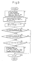
- Figure 9 is a flowchart for explaining a second embodiment.
- a monocular camera is used as the camera.
- image information obtained from the camera is processed in the image processor to calculate the approximate range R'gm to the target, the angle ⁇ gm, and the approximate height H'gm of the target.
- the range Rrn to the target, the angle ⁇ rn of the radar beam reflected by the target, and the relative velocity Vrn with respect to the target are calculated from the signal obtained by the radar.
- the range R'gm, the angle ⁇ gm, and the approximate height H'gm, obtained by the image processing are cycled through an i(0-m) loop.
- the range Rrn to the target, the angle ⁇ rn of the beam reflected by the target, and the relative velocity Vrn with respect to the target, obtained from the radar are cycled through a j(0-n) loop.
- S4 and S5 it is determined whether the target captured by the camera is the same target that has been captured by the radar.
- the range R'gm obtained by the camera and the range Rrn obtained by the radar are compared to determine whether the difference is within a predetermined range. If the difference is within the predetermined range (Yes), the process proceeds to S5.
- the angle ⁇ gm detected by the camera and the angle ⁇ rm detected by the radar are compared to determine whether the difference is within a predetermined range.
- the process proceeds to S6 to determine whether the approximate height H'g of the target captured by the camera is higher than the horizon level. If the answer is Yes, the target is recognized as being an overhead structure, and the range Rr to the target, the angle ⁇ r of the beam reflected by the target, and the relative velocity Vr with respect to the target, obtained from the radar, are deleted from the data concerning the vehicle ahead so that these data will not be treated as the data concerning the vehicle ahead.
- the data are deleted from the target data to be used for collision avoidance or vehicle-to-vehicle distance control, and the loop is ended in S8.
- the process also proceeds to S8 to end the loop.
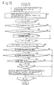
- Figure 10 is a flowchart for explaining a third embodiment.
- a monocular camera or a multiocular camera may be used as the camera system.
- the flowchart shown in Figure 10 is given assuming the use of a multiocular camera.
- image information obtained from the camera is processed in the image processor to calculate the range Rgm to the target and the angle ⁇ gm and height Hgm of the target.
- the range Rrn to the target, the angle ⁇ rn of the radar beam reflected by the target, and the relative velocity Vrn with respect to the target are calculated from the signal obtained by the radar. Further, in this embodiment, the reception level Prn of the radar is calculated.
- the range Rrn to the target, the angle ⁇ rn of the beam reflected by the target, the relative velocity Vrn with respect to the target, and the reception level Prn, obtained from the radar are cycled through a j(0-n) loop.
- S4 and S5 it is determined whether the target captured by the radar is a stationary object or not.
- S4 it is determined whether the range Rrn to the target captured by the radar is decreasing with time, that is, whether the radar-equipped vehicle is approaching the target. If it is approaching the target (Yes), the process proceeds to S5 to determine whether the reception level is decreasing with time. As shown in Figure 2, if the target is an overhead structure such as a bridge, the reception level decreases as the vehicle approaches the target.
- the detected target may be an overhead structure such as a bridge, so that a stationary object candidate flag Frn is set (S6). Then, the process proceeds to S7 to cycle through an i(0-m) loop. On the other hand, when the answer is No in S4 or S5, the process also proceeds to S7. Next, the process proceeds to S8 to cycle through the i(0-m) loop and j(0-n) loop.
- S9 and S10 it is determined whether the target captured by the camera is the same target that has been captured by the radar.
- the range Rgm obtained by the camera and the range Rrn obtained by the radar are compared to determine whether the difference is within a predetermined range. If the difference is within the predetermined range (Yes), the process proceeds to S10.
- the angle ⁇ gm detected by the camera and the angle ⁇ rn detected by the radar are compared to determine whether the difference is within a predetermined range.
- the process proceeds to S11 to determine whether the height Hg of the target captured by the camera is equal to or higher than a predetermined value.
- the predetermined value for Hg by which the detected target is judged to be an overhead structure or not, varies according to the range Rg or Rr to the target.
- a map defining the relationship between Rgm or Rrn and Hgm is prepared, and the determination is made by referring to the predetermined value for Hgm corresponding to Rgm or Rrn. If the answer is Yes, in this embodiment it is determined in S12 whether the stationary object candidate flag Frn is set or not. If the answer is Yes, the target is recognized as being an overhead structure which is a stationary object, and the range Rr to the target, the angle ⁇ r of the beam reflected by the target, and the relative velocity Vr with respect to the target, obtained from the radar, are deleted from the data concerning the vehicle ahead so that these data will not be treated as the data concerning the vehicle ahead (S13).
- the data are deleted from the target data to be used for collision avoidance or vehicle-to-vehicle distance control, and the loop is ended in S14.
- the process also proceeds to S8 to end the loop.
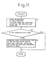
- FIG 11 is a flowchart illustrating a fourth embodiment.
- the radar system is not used, but only the camera system is used.
- the flowchart here is given assuming the use of a multiocular camera.
- vertical edge length Lgm is calculated in addition to the range Rgm to the target, the angle ⁇ gm and height Hgm of the target. Then, in S2, it is determined whether Lgm is increasing with time.
- the target is recognized as being an overhead structure, and the range Rgm to the target, the angle ⁇ gm of the beam reflected by the target, the height Hgm of the target, and Lgm, obtained by the camera system, are deleted from the data concerning the vehicle in front so that these data will not be treated as the data concerning the vehicle in front (S3).
- the fourth embodiment can also be applied when a monocular camera is used.
- vertical edge length Lgm is calculated in addition to the approximate range R'gm to the target, the angle ⁇ gm, and the approximate height H'g of the target.
- Lgm it is determined whether Lgm is increasing with time. If the answer is Yes, the target is recognized as being an overhead structure, and the range R'gm to the target, the angle ⁇ gm of the beam reflected by the target, the height H'gm of the target, and Lgm, obtained from the camera, are deleted from the data concerning the vehicle in front so that these data will not be treated as the data concerning the vehicle ahead (S3).
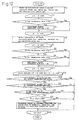
- Figure 12 is a flowchart illustrating a fifth embodiment.
- a monocular camera or a multiocular camera may be used as the camera.
- the flowchart shown in Figure 12 is given assuming the use of a multiocular camera.
- image information obtained from the camera is processed in the image processor to calculate the range Rgm to the target, the angle ⁇ gm and height Hgm of the target, and vertical edge length Lgm. Then, the process proceeds to S2 to cycle through an i(0-m) loop. Next, it is determined in S3 whether Lgm is increasing with time. If the answer is Yes, a flag Fgm indicating that the detected target is a stationary object candidate is set in S4.
- the process proceeds to S5 to cycle through the i(0-m) loop.
- S6 the range Rrn to the target detected by the radar, the angle ⁇ rn of the radar beam reflected by the target, the relative velocity Vrn with respect to the target, and the reception level Prn of the radar are calculated.
- S7 the range Rrn to the target, the angle ⁇ rn of the beam reflected by the target, the relative velocity Vrn with respect to the target, and the reception level Prn, obtained from the radar, are cycled through a j(0-n) loop.
- S8 and S9 it is determined whether the target captured by the radar is a stationary object or not.
- S8 it is determined whether the range Rrn to the target captured by the radar is decreasing with time, that is, whether the radar-equipped vehicle is approaching the target. If it is approaching the target (Yes), the process proceeds to S9 to determine whether the reception level is decreasing with time. If the answer is Yes, the detected target may be an overhead structure such as a bridge as shown in Figure 2, so that a stationary object candidate flag Frn is set (S10). Then, the process proceeds to S11 to cycle through the j(0-n) loop. When the answer is No in S8 or S9, the process also proceeds to S11. Next, the process proceeds to S12 to cycle through the i(0-m) loop and j(0-n) loop.
- S13 and S14 it is determined whether the target captured by the camera is the same target that has been captured by the radar.
- the range Rgm obtained by the camera and the range Rrn obtained by the radar are compared to determine whether the difference is within a predetermined range. If the difference is within the predetermined range (Yes), the process proceeds to S14.
- the angle ⁇ gm detected by the camera and the angle ⁇ rn detected by the radar are compared to determine whether the difference is within a predetermined range.
- the process proceeds to S15 to determine whether the height Hgm of the target captured by the camera is equal to or higher than a predetermined value. If the answer is Yes, it is determined in S16 whether the stationary object candidate flags Fgm and Frn are set or not.
- the target is recognized as being an overhead structure, and the range Rr to the target, the angle ⁇ r of the beam reflected by the target, and the relative velocity Vr with respect to the target, obtained from the radar, are deleted from the data concerning the vehicle in front so that these data will not be treated as the data concerning the vehicle in front (S17). That is, the data are deleted from the target data to be used for collision avoidance or vehicle-to-vehicle distance control, and the loop is ended in S18.
- the process also proceeds to S18 to end the loop.
- FIG 13 is a flowchart illustrating a sixth embodiment.
- the flowchart here is given assuming the use of a multiocular camera.
- horizontal edge length Wgm is calculated in addition to the range Rgm to the target, the angle ⁇ gm and the height Hg of the target.
- Wgm is increasing with time.
- horizontal edge length increases as the camera-equipped vehicle approaches it, as previously explained with reference to Figure 7.
- the target is recognized as being an overhead structure, and the range Rg to the target, the angle ⁇ g of the beam reflected by the target, the height Hg of the target, and Wg, obtained from the camera system, are deleted from the data concerning the vehicle in front so that these data will not be treated as the data concerning a vehicle in front (S3).
- the sixth embodiment can also be applied when a monocular camera is used.
- horizontal edge length Wgm is calculated in addition to the approximate range R'gm to the target, the angle ⁇ gm, and the approximate height H'g of the target. Then, it is determined in S2 whether Wgm is increasing with time. If the answer is Yes, the target is recognized as being an overhead structure, and the range R'gm to the target, the angle ⁇ gm of the beam reflected by the target, the height H'gm of the target, and Wg, obtained from the camera system, are deleted from the data concerning the vehicle ahead so that these data will not be treated as the data concerning the vehicle ahead (S3).
- Figure 14 is a flowchart illustrating a seventh embodiment.
- a monocular camera or a multiocular camera may be used as the camera.
- the flowchart shown in Figure 14 is given assuming the use of a multiocular camera.
- image information obtained from the camera is processed in the image processor to calculate the range Rgm to the target, the angle ⁇ gm and height Hgm of the target, and horizontal edge length Wgm. Then, the process proceeds to S2 to cycle through an i(0-m) loop. Next, it is determined in S3 whether Wgm is increasing with time. If the answer is Yes, a flag Fgm indicating that the detected target is a stationary object candidate is set in S4.
- the process proceeds to S5 to cycle through the i(0-m) loop.
- S6 the range Rrn to the target detected by the radar, the angle ⁇ rn of the radar beam reflected by the target, the relative velocity Vrn with respect to the target, and the reception level Prn of the radar are calculated.
- S7 the range Rrn to the target, the angle ⁇ rn of the beam reflected by the target, the relative velocity Vrn with respect to the target, and the reception level Prn, obtained from the radar, are cycled through a j(0-n) loop.
- S8 and S9 it is determined whether the target captured by the radar is a stationary object or not.
- S8 it is determined whether the range Rrn to the target captured by the radar is decreasing with time, that is, whether the radar-equipped vehicle is approaching the target. If it is approaching the target (Yes), the process proceeds to S9 to determine whether the reception level is decreasing with time. If the answer is Yes, the detected target may be a stationary structure such as a bridge as shown in Figure 2, so that a stationary object candidate flag Frn is set (S10). Then, the process proceeds to S11 to cycle through the j(0-n) loop. When the answer is No in S8 or S9, the process also proceeds to S11. Next, the process proceeds to S12 to cycle through the i(0-m) loop and j(0-n) loop.
- S13 and S14 it is determined whether the target captured by the camera is the same target that has been captured by the radar.
- the range Rgm obtained by the camera and the range Rrn obtained by the radar are compared to determine whether the difference is within a predetermined range. If the difference is within the predetermined range (Yes), the process proceeds to S14.
- the angle ⁇ gm detected by the camera and the angle ⁇ rm detected by the radar are compared to determine whether the difference is within a predetermined range.
- the process proceeds to S15 to determine whether the height Hgm of the target captured by the camera is equal to or higher than a predetermined value. If the answer is Yes, it is determined in S16 whether the stationary object candidate flags Fgm and Frn are set or not.
- the target is recognized as being an overhead structure, and the range Rr to the target, the angle ⁇ r of the beam reflected by the target, and the relative velocity Vr with respect to the target, obtained from the radar, are deleted from the data concerning the vehicle in front so that these data will not be treated as the data concerning the vehicle in front (S17). That is, the data are deleted from the target data to be used for collision avoidance or vehicle-to-vehicle distance control, and the loop is ended in S18.
- the process also proceeds to S18 to end the loop.
- stationary overhead object refers not only to the above-mentioned structures but also to stationary objects such as a road sign located on a roadside.
Landscapes
- Engineering & Computer Science (AREA)
- Remote Sensing (AREA)
- Radar, Positioning & Navigation (AREA)
- Physics & Mathematics (AREA)
- General Physics & Mathematics (AREA)
- Theoretical Computer Science (AREA)
- Computer Vision & Pattern Recognition (AREA)
- Computer Networks & Wireless Communication (AREA)
- Evolutionary Computation (AREA)
- Artificial Intelligence (AREA)
- Data Mining & Analysis (AREA)
- Multimedia (AREA)
- Evolutionary Biology (AREA)
- Health & Medical Sciences (AREA)
- Medical Informatics (AREA)
- Life Sciences & Earth Sciences (AREA)
- Bioinformatics & Cheminformatics (AREA)
- Bioinformatics & Computational Biology (AREA)
- General Health & Medical Sciences (AREA)
- Computing Systems (AREA)
- Databases & Information Systems (AREA)
- Software Systems (AREA)
- General Engineering & Computer Science (AREA)
- Electromagnetism (AREA)
- Spectroscopy & Molecular Physics (AREA)
- Traffic Control Systems (AREA)
- Radar Systems Or Details Thereof (AREA)
Abstract
A method for detecting a target located above a road
by using a camera and a radar system, wherein when it is
determined that the target captured by the camera is the
same target that has been captured by the radar, and when
it is determined from an image captured by the camera
that the target is at a height higher than road level,
the method determines that the target is a stationary
object located above the road. Further, when it is
determined that the distance to the target captured by
the camera or the radar is decreasing, and that the
reception level from the target captured by the radar is
also decreasing, the method determines that the target is
a stationary object located above the road.
Description
The present invention relates to a method for
detecting a stationary object located above a road, in
particular, an overhead structure such as a bridge over a
road, by using radar detection in combination with camera
image processing.
A scanning radar scans a radar beam by moving the
beam from left to right or from right to left at very
small step angles within a predetermined time. At each
step angle, the radar beam is projected from the radar-equipped
vehicle toward a vehicle traveling in front, and
the reflected wave from the vehicle in front is received
and processed to detect the presence of the vehicle in
front and compute the distance and relative velocity with
respect to that vehicle.
In the case of a radar, as the beam is usually
scanned in lateral directions as described above, it is
difficult to obtain accurate information on height. As a
result, when an overhead structure such as a bridge over
the road ahead or a structure such as a road sign located
on the roadside in front is detected, it may not be
possible to distinctly identify whether the detected
object is a stationary structure located above the road
or on the roadside in front or a vehicle traveling in
front.
It is an object of the present invention to provide
a method for detecting a stationary object located above
a road, which, when an object is detected in the path in
front, can identify whether the detected object is a
vehicle traveling in front or a structure, such as a
bridge or road sign, located above the road or on the
roadside in front.
According to the method of the present invention,
the method uses a camera and a radar system, and when it
is determined that the target captured by the camera is
the same target that has been captured by the radar, and
when it is determined from an image captured by the
camera that the target is at a height higher than the
horison level, the method determines that the target is a
stationary object located above the road.
Further, according to the method of the present
invention, when it is determined that the distance to the
target captured by the camera or the radar is decreasing,
and that a reception level from the target captured by
the radar is also decreasing, the method determines that
the target is a stationary object located above the road.
According to the method of the present invention,
when it is determined that the target captured by the
camera is the same target that has been captured by the
radar, and when it is determined from the image captured
by the camera that the height of the target, for example,
the height above the road in the case of a road sign or
the like, is equal to or higher than a predetermined
value, the method determines that the target is a
stationary object located above the road.
According to the method of the present invention,
the method uses a camera system, and when it is
determined that the length of a vertical edge or
horizontal edge of the target captured by the camera is
increasing with time, the method determines that the
target is a stationary object located above the road.
The camera system comprises a multiocular camera or
a monocular camera. The method of the present invention
determines that the two targets are the same target when
the difference between the distance Rg to the target
captured by the camera and the distance Rr to the target
captured by the radar and the difference between an angle
g of the target captured by the camera and an angle r
of the target captured by the radar are within a
predetermined range.
When it is determined that the target is a
stationary object located above the road, data obtained
from the target is deleted from data concerning a vehicle
traveling in front.
According to the method of the present invention,
since information about the height of the target, which
cannot be obtained by the radar system alone, is obtained
from an image captured by the camera system, it can be
determined in a simple manner whether the detected target
is a stationary object located above the road.
Further, according to the method of the present
invention, whether the detected target is a stationary
object located above the road can also be determined in a
simple manner by detecting a variation in the reception
level obtained by the radar system.
Furthermore, according to the method of the present
invention, whether the detected target is a stationary
object located above the road can also be determined in a
simple manner from edge information which is image
information obtained from the camera system.
When the above methods are combined, it becomes
possible to determined in a simple and more reliable
manner whether the detected target is a stationary object
located above the road.
Figure 1 is a block diagram showing the
configuration of an image recognition apparatus used in
the method of the present invention. In the figure,
reference numeral 10 is an image recognition part, and 20
is an application part. In the image recognition part
10, reference numeral 13 is a radar, for example, a
millimeter-wave radar, which detects the distance,
relative velocity, detection angle, reception level, etc.
with respect to an object located in the path in front
such as a vehicle traveling in front. These pieces of
information detected by the radar are input to an object
recognizer 14. On the other hand, reference numeral 11
is a camera system which, in the case of a multiocular
camera, comprises a plurality of cameras, for example,
two cameras, that are mounted spaced apart left and right
on a vehicle in such a manner as to be able to capture an
image in front of the vehicle. In the case of a
monocular camera, a single camera is mounted on the
vehicle in such a manner as to be able to capture an
image in front of the vehicle. Image information
obtained from the camera 11 is supplied to an image
processor 12 where the image information is processed to
obtain information on the distance, relative velocity,
detection angle, height, width, etc. concerning the
object located in front such as a vehicle traveling in
front. These pieces of information are also input to the
object recognizer 14 where the information is processed
to obtain information concerning the vehicle traveling in
front, such as the distance, relative velocity, etc. of
the vehicle traveling in front. Information concerning
an object located on the roadside or a structure, road
sign, etc. located above the road in front can also be
obtained at the same time.
These pieces of information are input to a control
ECU 21 which, based on the input information, controls
the accelerator 22, brakes 23, steering 24, etc.
Figure 2 is a diagram showing how a structure
located above the road in front is detected by the radar
when the structure is, for example, an overhead bridge.
In the figure, reference numeral 1 is a vehicle equipped
with the radar, 2 is a radar beam projected from the
radar-equipped vehicle, and 3 is the bridge as the
structure located above the road in front. The graph in
the lower part of Figure 2 shows the reception level of
the radar as a function of the distance from the bridge 3
to the vehicle 1. As shown by the graph, the reception
level decreases as the vehicle approaches the bridge.
Though not shown in the figure, the reception level also
decreases when the bridge is located more than a certain
distance away from the vehicle.
Figure 3 is a graph showing how the reception level
changes with the angle of the radar beam when the bridge
3 is detected by the radar as shown in Figure 2. The
radar beam 3 shown in Figure 2 is scanned left and right
in lateral directions at predetermined step angles; here,
the reception level changes as the angle of the beam
changes. When the target is a bridge as illustrated in
Figure 2, the reception level usually changes as shown by
the graph in Figure 3. More specifically, when the scan
angle of the radar is plotted along the horizontal axis
and the reception level along the vertical axis, since
the bridge extends horizontally, the reception level of
the beam reflected by the bridge is the highest when the
beam is projected from the vehicle at a projection angle
of 0 degree, that is, in the straight forward direction,
and the reception level decreases as the angle increases
to the left or the right.
Figure 4A is a diagram showing an image captured by
the camera. Figure 4B shows a range image created based
on distances measured by the camera. By applying image
processing to the signals captured by the camera,
information concerning the location of a particular
object in the image can be acquired. Furthermore, image
edge information and range information can also be
obtained. The edge information is obtained by extracting
the points defining the boundaries between light and dark
portions of the image, while the range information is
obtained by comparing the images captured by the
multiocular camera and calculating the parallax between
them.
Even in the case of an image captured by a monocular
camera, edge information can be obtained for pattern
recognition, and the approximate distance to the target
object, the angle of its location, and the approximate
height of the objet can be determined.
Figure 4B is a diagram showing one example of the
range image when the distance from the vehicle to the
bridge is about 60 m and the field of view seen from the
vehicle is 0°±20°. As shown, it can be seen from the
image captured by the camera that the bridge is located
at a distance of 60 m from the vehicle while the road
surfaces in front are at 10 m and 15 m distances,
respectively. The diagram shown here is created from the
range image obtained by calculating the parallax over the
entire image. From this diagram it can be determined
that the object detected about 60 m in front is an object
located at a height higher than the horizon level, and is
not an object located on the road.
Figure 5 shows an image captured by the camera when
abridge 3 with a road sign 4 attached to it is located
in the path in front. Figure 6 shows an edge image
created by extracting vertical edges from the image shown
in Figure 5. As can be seen, when the vertical edges are
extracted, only the vertical lines defining the
supporting structure of the bridge 3 and the sign 4 are
shown in the image. The vertical edges become longer and
move upward in the image as the vehicle approaches the
bridge. Figure 7 shows an edge image created by
extracting horizontal edges from the image shown in
Figure 5. As can be seen, when the horizontal edges are
extracted, only the horizontal lines defining the
supporting structure of the bridge 3 and the sign 4 are
shown in the image. As in the case of the vertical
edges, the horizontal edges become longer in the image as
the vehicle approaches the bridge.
Next, embodiments of the present invention will be
described with reference to flowcharts.
Figure 8 is a flowchart for explaining a first
embodiment. In this embodiment, a multiocular camera is
used as the camera. In S1, image information obtained
from the camera is processed in the image processor to
calculate the range Rgm to the target, the angle gm
between the location of the target and the line of sight
of the camera, and the height Hgm of the target. On the
other hand, in S2, the range Rrn to the target, the angle
rn of the radar beam reflected by the target, and the
relative velocity Vrn with respect to the target are
calculated from the signal obtained by the radar. Then
in S3, the range Rgm, angle gm, and height Hgm obtained
by the image processing are cycled through an i(0-m)
loop. That is, Rg, g, and Hg are calculated in each
cycle. Likewise, the range Rrn to the target, the angle
rn of the beam reflected by the target, and the relative
velocity Vrn with respect to the target, obtained from
the radar, are cycled through a j(0-n) loop. That is,
Rr, r, and Vr are calculated in each cycle. Next, in S4
and S5, it is determined whether the target captured by
the camera is the same target that has been captured by
the radar. First, in S4, the range Rgm obtained by the
camera and the range Rrn obtained by the radar are
compared to determine whether the difference is within a
predetermined range. If the difference is within the
predetermined range (Yes), the process proceeds to S5.
In S5, the angle gm detected by the camera and the angle
rn detected by the radar are compared to determine
whether the difference is within a predetermined range.
If the answer is Yes, it is determined that the target
captured by the camera is the same target that has been
captured by the radar, as the range Rg and angle g of
the target captured by the camera are approximately equal
to the range Rr and angle r of the target captured by
the radar. Then, the process proceeds to S6 to determine
whether the height Hg of the target captured by the
camera is higher than the horizon level. If the answer
is Yes, the target is recognized as being an overhead
structure, and the range Rr to the target, the angle r
of the beam reflected by the target, and the relative
velocity Vr with respect to the target, obtained from the
radar, are deleted from data concerning the vehicle
traveling in front so that these data will not be treated
as the data concerning the vehicle ahead. That is, the
data are deleted from the target data to be used for
collision avoidance or vehicle-to-vehicle distance
control, and the loop is ended in S8. On the other hand,
when the answer in any one of steps S4 to S6 is No, the
process also proceeds to S8 to end the loop.
Figure 9 is a flowchart for explaining a second
embodiment. In this embodiment, a monocular camera is
used as the camera. In S1, image information obtained
from the camera is processed in the image processor to
calculate the approximate range R'gm to the target, the
angle gm, and the approximate height H'gm of the target.
On the other hand, in S2, the range Rrn to the target,
the angle rn of the radar beam reflected by the target,
and the relative velocity Vrn with respect to the target
are calculated from the signal obtained by the radar.
Then in S3, the range R'gm, the angle gm, and the
approximate height H'gm, obtained by the image
processing, are cycled through an i(0-m) loop. Likewise,
the range Rrn to the target, the angle rn of the beam
reflected by the target, and the relative velocity Vrn
with respect to the target, obtained from the radar, are
cycled through a j(0-n) loop. Next, in S4 and S5, it is
determined whether the target captured by the camera is
the same target that has been captured by the radar.
First, in S4, the range R'gm obtained by the camera and
the range Rrn obtained by the radar are compared to
determine whether the difference is within a
predetermined range. If the difference is within the
predetermined range (Yes), the process proceeds to S5.
In S5, the angle gm detected by the camera and the angle
rm detected by the radar are compared to determine
whether the difference is within a predetermined range.
If the difference is within the predetermined range
(Yes), it is determined that the target captured by the
camera is the same target that has been captured by the
radar, as the range R'g and angle g of the target
captured by the camera are approximately equal to the
range Rr and angle r of the target captured by the
radar. Then, the process proceeds to S6 to determine
whether the approximate height H'g of the target captured
by the camera is higher than the horizon level. If the
answer is Yes, the target is recognized as being an
overhead structure, and the range Rr to the target, the
angle r of the beam reflected by the target, and the
relative velocity Vr with respect to the target, obtained
from the radar, are deleted from the data concerning the
vehicle ahead so that these data will not be treated as
the data concerning the vehicle ahead. That is, the data
are deleted from the target data to be used for collision
avoidance or vehicle-to-vehicle distance control, and the
loop is ended in S8. On the other hand, when the answer
in any one of steps S4 to S6 is No, the process also
proceeds to S8 to end the loop.
Figure 10 is a flowchart for explaining a third
embodiment. In this embodiment, either a monocular
camera or a multiocular camera may be used as the camera
system. The flowchart shown in Figure 10 is given
assuming the use of a multiocular camera. In S1, image
information obtained from the camera is processed in the
image processor to calculate the range Rgm to the target
and the angle gm and height Hgm of the target. On the
other hand, in S2, the range Rrn to the target, the angle
rn of the radar beam reflected by the target, and the
relative velocity Vrn with respect to the target are
calculated from the signal obtained by the radar.
Further, in this embodiment, the reception level Prn of
the radar is calculated. Then in S3, the range Rrn to
the target, the angle rn of the beam reflected by the
target, the relative velocity Vrn with respect to the
target, and the reception level Prn, obtained from the
radar, are cycled through a j(0-n) loop. Next, in S4 and
S5, it is determined whether the target captured by the
radar is a stationary object or not. First, in S4, it is
determined whether the range Rrn to the target captured
by the radar is decreasing with time, that is, whether
the radar-equipped vehicle is approaching the target. If
it is approaching the target (Yes), the process proceeds
to S5 to determine whether the reception level is
decreasing with time. As shown in Figure 2, if the
target is an overhead structure such as a bridge, the
reception level decreases as the vehicle approaches the
target. Therefore, if the answer is Yes, the detected
target may be an overhead structure such as a bridge, so
that a stationary object candidate flag Frn is set (S6).
Then, the process proceeds to S7 to cycle through an i(0-m)
loop. On the other hand, when the answer is No in S4
or S5, the process also proceeds to S7. Next, the
process proceeds to S8 to cycle through the i(0-m) loop
and j(0-n) loop.
Next, in S9 and S10, it is determined whether the
target captured by the camera is the same target that has
been captured by the radar. First, in S9, the range Rgm
obtained by the camera and the range Rrn obtained by the
radar are compared to determine whether the difference is
within a predetermined range. If the difference is
within the predetermined range (Yes), the process
proceeds to S10. In S10, the angle gm detected by the
camera and the angle rn detected by the radar are
compared to determine whether the difference is within a
predetermined range. If the difference is within the
predetermined range (Yes), it is determined that the
target captured by the camera is the same target that has
been captured by the radar, as the range Rg and angle g
of the target captured by the camera are approximately
equal to the range Rr and angle r of the target captured
by the radar. Then, the process proceeds to S11 to
determine whether the height Hg of the target captured by
the camera is equal to or higher than a predetermined
value. In this case, the predetermined value for Hg, by
which the detected target is judged to be an overhead
structure or not, varies according to the range Rg or Rr
to the target. Accordingly, a map defining the
relationship between Rgm or Rrn and Hgm is prepared, and
the determination is made by referring to the
predetermined value for Hgm corresponding to Rgm or Rrn.
If the answer is Yes, in this embodiment it is determined
in S12 whether the stationary object candidate flag Frn
is set or not. If the answer is Yes, the target is
recognized as being an overhead structure which is a
stationary object, and the range Rr to the target, the
angle r of the beam reflected by the target, and the
relative velocity Vr with respect to the target, obtained
from the radar, are deleted from the data concerning the
vehicle ahead so that these data will not be treated as
the data concerning the vehicle ahead (S13). That is,
the data are deleted from the target data to be used for
collision avoidance or vehicle-to-vehicle distance
control, and the loop is ended in S14. On the other
hand, when the answer in any one of steps S9 to 12 is No,
the process also proceeds to S8 to end the loop.
In the flowchart of Figure 10 illustrating the third
embodiment, as a multiocular camera is used, height Hgm
is calculated in S1, and it is determined in S11 whether
Hgm is equal to or higher than the predetermined value.
On the other hand, when a monocular camera is used,
approximate height H'gm is calculated in S1, and it is
determined in S11 whether H'gm is equal to or higher than
the predetermined value.
Figure 11 is a flowchart illustrating a fourth
embodiment. In this embodiment, the radar system is not
used, but only the camera system is used. The flowchart
here is given assuming the use of a multiocular camera.
In S1, vertical edge length Lgm is calculated in addition
to the range Rgm to the target, the angle gm and height
Hgm of the target. Then, in S2, it is determined whether
Lgm is increasing with time. If the answer is Yes, the
target is recognized as being an overhead structure, and
the range Rgm to the target, the angle gm of the beam
reflected by the target, the height Hgm of the target,
and Lgm, obtained by the camera system, are deleted from
the data concerning the vehicle in front so that these
data will not be treated as the data concerning the
vehicle in front (S3).
The fourth embodiment can also be applied when a
monocular camera is used. In this case, in S1, vertical
edge length Lgm is calculated in addition to the
approximate range R'gm to the target, the angle gm, and
the approximate height H'g of the target. Then, in S2,
it is determined whether Lgm is increasing with time. If
the answer is Yes, the target is recognized as being an
overhead structure, and the range R'gm to the target, the
angle gm of the beam reflected by the target, the height
H'gm of the target, and Lgm, obtained from the camera,
are deleted from the data concerning the vehicle in front
so that these data will not be treated as the data
concerning the vehicle ahead (S3).
Figure 12 is a flowchart illustrating a fifth
embodiment. In this embodiment, either a monocular
camera or a multiocular camera may be used as the camera.
The flowchart shown in Figure 12 is given assuming the
use of a multiocular camera. In S1, image information
obtained from the camera is processed in the image
processor to calculate the range Rgm to the target, the
angle gm and height Hgm of the target, and vertical edge
length Lgm. Then, the process proceeds to S2 to cycle
through an i(0-m) loop. Next, it is determined in S3
whether Lgm is increasing with time. If the answer is
Yes, a flag Fgm indicating that the detected target is a
stationary object candidate is set in S4. Then, the
process proceeds to S5 to cycle through the i(0-m) loop.
Next, in S6, the range Rrn to the target detected by the
radar, the angle rn of the radar beam reflected by the
target, the relative velocity Vrn with respect to the
target, and the reception level Prn of the radar are
calculated. Then in S7, the range Rrn to the target, the
angle rn of the beam reflected by the target, the
relative velocity Vrn with respect to the target, and the
reception level Prn, obtained from the radar, are cycled
through a j(0-n) loop. Next, in S8 and S9, it is
determined whether the target captured by the radar is a
stationary object or not. First, in S8, it is determined
whether the range Rrn to the target captured by the radar
is decreasing with time, that is, whether the radar-equipped
vehicle is approaching the target. If it is
approaching the target (Yes), the process proceeds to S9
to determine whether the reception level is decreasing
with time. If the answer is Yes, the detected target may
be an overhead structure such as a bridge as shown in
Figure 2, so that a stationary object candidate flag Frn
is set (S10). Then, the process proceeds to S11 to cycle
through the j(0-n) loop. When the answer is No in S8 or
S9, the process also proceeds to S11. Next, the process
proceeds to S12 to cycle through the i(0-m) loop and j(0-n)
loop.
Next, in S13 and S14, it is determined whether the
target captured by the camera is the same target that has
been captured by the radar. First, in S13, the range Rgm
obtained by the camera and the range Rrn obtained by the
radar are compared to determine whether the difference is
within a predetermined range. If the difference is
within the predetermined range (Yes), the process
proceeds to S14. In S14, the angle gm detected by the
camera and the angle rn detected by the radar are
compared to determine whether the difference is within a
predetermined range. If the difference is within the
predetermined range (Yes), it is determined that the
target captured by the camera is the same target that has
been captured by the radar, as the range Rg and angle g
of the target captured by the camera are approximately
equal to the range Rr and angle r of the target captured
by the radar. Then, the process proceeds to S15 to
determine whether the height Hgm of the target captured
by the camera is equal to or higher than a predetermined
value. If the answer is Yes, it is determined in S16
whether the stationary object candidate flags Fgm and Frn
are set or not. If the answer is Yes, the target is
recognized as being an overhead structure, and the range
Rr to the target, the angle r of the beam reflected by
the target, and the relative velocity Vr with respect to
the target, obtained from the radar, are deleted from the
data concerning the vehicle in front so that these data
will not be treated as the data concerning the vehicle in
front (S17). That is, the data are deleted from the
target data to be used for collision avoidance or
vehicle-to-vehicle distance control, and the loop is
ended in S18. On the other hand, when the answer in any
one of steps S13 to 16 is No, the process also proceeds
to S18 to end the loop.
In the flowchart of Figure 12 illustrating the fifth
embodiment, as a multiocular camera is used, height Hgm
is calculated in S1, and it is determined in S15 whether
Hgm is higher than the predetermined value. On the other
hand, when a monocular camera is used, approximate height
H'gm is calculated in S1, and it is determined in S15
whether H'gm is equal to or higher than the predetermined
value.
Figure 13 is a flowchart illustrating a sixth
embodiment. The flowchart here is given assuming the use
of a multiocular camera. In S1, horizontal edge length
Wgm is calculated in addition to the range Rgm to the
target, the angle gm and the height Hg of the target.
Then, in S2, it is determined whether Wgm is increasing
with time. In the case of a road sign or the like,
horizontal edge length increases as the camera-equipped
vehicle approaches it, as previously explained with
reference to Figure 7. Therefore, if the answer is Yes,
the target is recognized as being an overhead structure,
and the range Rg to the target, the angle g of the beam
reflected by the target, the height Hg of the target, and
Wg, obtained from the camera system, are deleted from the
data concerning the vehicle in front so that these data
will not be treated as the data concerning a vehicle in
front (S3).
The sixth embodiment can also be applied when a
monocular camera is used. In this case, in S1,
horizontal edge length Wgm is calculated in addition to
the approximate range R'gm to the target, the angle gm,
and the approximate height H'g of the target. Then, it
is determined in S2 whether Wgm is increasing with time.
If the answer is Yes, the target is recognized as being
an overhead structure, and the range R'gm to the target,
the angle gm of the beam reflected by the target, the
height H'gm of the target, and Wg, obtained from the
camera system, are deleted from the data concerning the
vehicle ahead so that these data will not be treated as
the data concerning the vehicle ahead (S3).
Figure 14 is a flowchart illustrating a seventh
embodiment. In this embodiment, either a monocular
camera or a multiocular camera may be used as the camera.
The flowchart shown in Figure 14 is given assuming the
use of a multiocular camera. In S1, image information
obtained from the camera is processed in the image
processor to calculate the range Rgm to the target, the
angle gm and height Hgm of the target, and horizontal
edge length Wgm. Then, the process proceeds to S2 to
cycle through an i(0-m) loop. Next, it is determined in
S3 whether Wgm is increasing with time. If the answer is
Yes, a flag Fgm indicating that the detected target is a
stationary object candidate is set in S4. Then, the
process proceeds to S5 to cycle through the i(0-m) loop.
Next, in S6, the range Rrn to the target detected by the
radar, the angle rn of the radar beam reflected by the
target, the relative velocity Vrn with respect to the
target, and the reception level Prn of the radar are
calculated. Then in S7, the range Rrn to the target, the
angle rn of the beam reflected by the target, the
relative velocity Vrn with respect to the target, and the
reception level Prn, obtained from the radar, are cycled
through a j(0-n) loop. Next, in S8 and S9, it is
determined whether the target captured by the radar is a
stationary object or not. First, in S8, it is determined
whether the range Rrn to the target captured by the radar
is decreasing with time, that is, whether the radar-equipped
vehicle is approaching the target. If it is
approaching the target (Yes), the process proceeds to S9
to determine whether the reception level is decreasing
with time. If the answer is Yes, the detected target may
be a stationary structure such as a bridge as shown in
Figure 2, so that a stationary object candidate flag Frn
is set (S10). Then, the process proceeds to S11 to cycle
through the j(0-n) loop. When the answer is No in S8 or
S9, the process also proceeds to S11. Next, the process
proceeds to S12 to cycle through the i(0-m) loop and j(0-n)
loop.
Next, in S13 and S14, it is determined whether the
target captured by the camera is the same target that has
been captured by the radar. First, in S13, the range Rgm
obtained by the camera and the range Rrn obtained by the
radar are compared to determine whether the difference is
within a predetermined range. If the difference is
within the predetermined range (Yes), the process
proceeds to S14. In S14, the angle gm detected by the
camera and the angle rm detected by the radar are
compared to determine whether the difference is within a
predetermined range. If the difference is within the
predetermined range (Yes), it is determined that the
target captured by the camera is the same target that has
been captured by the radar, as the range Rg and angle g
of the target captured by the camera are approximately
equal to the range Rr and angle r of the target captured
by the radar. Then, the process proceeds to S15 to
determine whether the height Hgm of the target captured
by the camera is equal to or higher than a predetermined
value. If the answer is Yes, it is determined in S16
whether the stationary object candidate flags Fgm and Frn
are set or not. If the answer is Yes, the target is
recognized as being an overhead structure, and the range
Rr to the target, the angle r of the beam reflected by
the target, and the relative velocity Vr with respect to
the target, obtained from the radar, are deleted from the
data concerning the vehicle in front so that these data
will not be treated as the data concerning the vehicle in
front (S17). That is, the data are deleted from the
target data to be used for collision avoidance or
vehicle-to-vehicle distance control, and the loop is
ended in S18. On the other hand, when the answer in any
one of steps S13 to 16 is No, the process also proceeds
to S18 to end the loop.
In the flowchart of Figure 14 illustrating the
seventh embodiment, since a multiocular camera is used,
height Hgm is calculated in S1, and it is determined in
S15 whether Hgm is higher than the predetermined value.
On the other hand, when a monocular camera is used,
approximate height H'gm is calculated in S1, and it is
determined in S15 whether H'gm is equal to or higher than
the predetermined value.
The present invention has been described by taking a
bridge or a road sign located above a road as an example
of the stationary overhead structure, but it should be
understood that, in the present invention, the term
stationary overhead object refers not only to the above-mentioned
structures but also to stationary objects such
as a road sign located on a roadside.
Claims (11)
- A method for detecting a stationary object located above a road by using a camera system and a radar system wherein, when it is determined that a target captured by a camera and a target captured by a radar are the same target, and when it is determined from an image captured by the camera that the target is at a height higher than the horison level, the method determines that the target is a stationary object located above the road.
- A method for detecting a stationary object located above a road by using a camera system and a radar system wherein, when it is determined that a distance to a target captured by a camera or a radar is decreasing, and that a reception level from the target captured by the radar is also decreasing, the method determines that the target is a stationary object located above the road.
- A method for detecting a stationary object located above a road as claimed in claim 2 wherein, when it is determined that the target captured by the camera is the same target that has been captured by the radar, and when it is determined from an image captured by the camera that the target is at a height equal to or higher than a predetermined value, the method determines that the target is a stationary object located above the road.
- A method for detecting a stationary object located above a road by using a camera system wherein, when it is determined that a vertical edge of a target captured by a camera is increasing in length with time, the method determines that the target is a stationary object located above the road.
- A method for detecting a stationary object located above a road by using a camera system, wherein when it is determined that a horizontal edge of a target captured by a camera is increasing in length with time, the method determines that the target is a stationary object located above the road.
- A method for detecting a stationary object located above a road as claimed in claim 4 or 5 wherein, when it is determined that a reception level from a target captured by a radar is decreasing, the method determines that the target is a stationary object located above the road.
- A method for detecting a stationary object located above a road as claimed in claim 6 wherein, when it is determined that the target captured by the camera is the same target that has been captured by the radar, and when it is determined from an image captured by the camera that the target is at a height higher than road level, the method determines that the target is a stationary object located above the road.
- A method for detecting a stationary object located above a road as claimed in claim 1, 2, 4, or 5, wherein the camera system comprises a multiocular camera or a monocular camera.
- A method for detecting a stationary object located above a road as claimed in claim 1, 3, or 7, wherein it is determined that the two targets are the same target when the difference between the distance Rg to the target captured by the camera and the distance Rr to the target captured by the radar and the difference between an angle g of the target captured by the camera and an angle r of the target captured by the radar are within a predetermined range.
- A method for detecting a stationary object located above a road as claimed in claim 1, 2, 4, or 5 wherein, when it is determined that the target is a stationary object located above the road, data obtained from the target is deleted from data concerning a vehicle traveling in front.
- A method for detecting a stationary object located above a road as claimed in any one of claims 1 to 10, wherein the stationary object located above the road is a stationary object located above the road or on a roadside.
Priority Applications (1)
| Application Number | Priority Date | Filing Date | Title |
|---|---|---|---|
| EP07118813A EP1881345B1 (en) | 2000-12-20 | 2001-12-19 | Method for detecting stationary object located above road |
Applications Claiming Priority (3)
| Application Number | Priority Date | Filing Date | Title |
|---|---|---|---|
| JP2000387571A JP2002189075A (en) | 2000-12-20 | 2000-12-20 | Method for detecting stationary on-road object |
| JP2000387571 | 2000-12-20 | ||
| PCT/JP2001/011156 WO2002050568A1 (en) | 2000-12-20 | 2001-12-19 | Method for detecting stationary object on road |
Related Child Applications (1)
| Application Number | Title | Priority Date | Filing Date |
|---|---|---|---|
| EP07118813A Division EP1881345B1 (en) | 2000-12-20 | 2001-12-19 | Method for detecting stationary object located above road |
Publications (2)
| Publication Number | Publication Date |
|---|---|
| EP1345045A1 true EP1345045A1 (en) | 2003-09-17 |
| EP1345045A4 EP1345045A4 (en) | 2005-10-26 |
Family
ID=18854473
Family Applications (2)
| Application Number | Title | Priority Date | Filing Date |
|---|---|---|---|
| EP07118813A Expired - Lifetime EP1881345B1 (en) | 2000-12-20 | 2001-12-19 | Method for detecting stationary object located above road |
| EP01271549A Withdrawn EP1345045A4 (en) | 2000-12-20 | 2001-12-19 | Method for detecting stationary object on road |
Family Applications Before (1)
| Application Number | Title | Priority Date | Filing Date |
|---|---|---|---|
| EP07118813A Expired - Lifetime EP1881345B1 (en) | 2000-12-20 | 2001-12-19 | Method for detecting stationary object located above road |
Country Status (6)
| Country | Link |
|---|---|
| US (1) | US6670912B2 (en) |
| EP (2) | EP1881345B1 (en) |
| JP (1) | JP2002189075A (en) |
| KR (1) | KR100461228B1 (en) |
| DE (1) | DE60139967D1 (en) |
| WO (1) | WO2002050568A1 (en) |
Cited By (1)
| Publication number | Priority date | Publication date | Assignee | Title |
|---|---|---|---|---|
| EP2023158A3 (en) * | 2007-07-25 | 2009-03-04 | Fujitsu Ten Limited | Automotive forward looking sensor with identification of traversable stationary obstacles in the driving path |
Families Citing this family (69)
| Publication number | Priority date | Publication date | Assignee | Title |
|---|---|---|---|---|
| US10361802B1 (en) | 1999-02-01 | 2019-07-23 | Blanding Hovenweep, Llc | Adaptive pattern recognition based control system and method |
| US8352400B2 (en) | 1991-12-23 | 2013-01-08 | Hoffberg Steven M | Adaptive pattern recognition based controller apparatus and method and human-factored interface therefore |
| US7966078B2 (en) | 1999-02-01 | 2011-06-21 | Steven Hoffberg | Network media appliance system and method |
| US10298735B2 (en) | 2001-04-24 | 2019-05-21 | Northwater Intellectual Property Fund L.P. 2 | Method and apparatus for dynamic configuration of a multiprocessor health data system |
| US7146260B2 (en) * | 2001-04-24 | 2006-12-05 | Medius, Inc. | Method and apparatus for dynamic configuration of multiprocessor system |
| US7027615B2 (en) * | 2001-06-20 | 2006-04-11 | Hrl Laboratories, Llc | Vision-based highway overhead structure detection system |
| US6771208B2 (en) * | 2002-04-24 | 2004-08-03 | Medius, Inc. | Multi-sensor system |
| US7178049B2 (en) | 2002-04-24 | 2007-02-13 | Medius, Inc. | Method for multi-tasking multiple Java virtual machines in a secure environment |
| JP2004226158A (en) * | 2003-01-21 | 2004-08-12 | Fujitsu Ten Ltd | Fm-cw radar device |
| JP3918791B2 (en) * | 2003-09-11 | 2007-05-23 | トヨタ自動車株式会社 | Object detection device |
| JP3941765B2 (en) * | 2003-09-11 | 2007-07-04 | トヨタ自動車株式会社 | Object detection device |
| WO2005086620A2 (en) | 2003-10-10 | 2005-09-22 | L-3 Communications Security And Detection Systems | Mmw contraband screening system |
| US7389171B2 (en) * | 2003-12-22 | 2008-06-17 | Ford Global Technologies Llc | Single vision sensor object detection system |
| JP4763250B2 (en) * | 2004-04-09 | 2011-08-31 | 株式会社デンソー | Object detection device |
| US7561720B2 (en) * | 2004-04-30 | 2009-07-14 | Visteon Global Technologies, Inc. | Single camera system and method for range and lateral position measurement of a preceding vehicle |
| US7337650B1 (en) | 2004-11-09 | 2008-03-04 | Medius Inc. | System and method for aligning sensors on a vehicle |
| US7561721B2 (en) * | 2005-02-02 | 2009-07-14 | Visteon Global Technologies, Inc. | System and method for range measurement of a preceding vehicle |
| US20070031008A1 (en) * | 2005-08-02 | 2007-02-08 | Visteon Global Technologies, Inc. | System and method for range measurement of a preceding vehicle |
| US7706978B2 (en) * | 2005-09-02 | 2010-04-27 | Delphi Technologies, Inc. | Method for estimating unknown parameters for a vehicle object detection system |
| US7623681B2 (en) * | 2005-12-07 | 2009-11-24 | Visteon Global Technologies, Inc. | System and method for range measurement of a preceding vehicle |
| US7877209B2 (en) * | 2006-09-26 | 2011-01-25 | Harris Steven M | Radar collison warning system for rooftop mounted cargo |
| DE102007002738A1 (en) * | 2007-01-18 | 2008-07-24 | Robert Bosch Gmbh | Method for supporting a parking operation of a vehicle |
| FR2917869B1 (en) * | 2007-06-25 | 2009-10-09 | Valeo Vision Sa | METHOD FOR DETECTING A TARGET OBJECT |
| DE102007053989A1 (en) * | 2007-11-13 | 2009-05-14 | Wabco Gmbh | Method and arrangement for warning against obstacles with insufficient headroom and / or insufficient passage width |
| JP2009230229A (en) * | 2008-03-19 | 2009-10-08 | Toyota Motor Corp | Object detection device |
| CN102105810B (en) * | 2008-07-24 | 2013-10-23 | 皇家飞利浦电子股份有限公司 | Three-dimensional (3-D) frame capture |
| US9358924B1 (en) | 2009-05-08 | 2016-06-07 | Eagle Harbor Holdings, Llc | System and method for modeling advanced automotive safety systems |
| US8417490B1 (en) | 2009-05-11 | 2013-04-09 | Eagle Harbor Holdings, Llc | System and method for the configuration of an automotive vehicle with modeled sensors |
| JP5551891B2 (en) * | 2009-06-18 | 2014-07-16 | 富士通テン株式会社 | Signal processing apparatus and radar apparatus |
| JP2011117896A (en) * | 2009-12-07 | 2011-06-16 | Honda Elesys Co Ltd | Electronic scanning type radar device and computer program |
| JP5629521B2 (en) * | 2010-07-29 | 2014-11-19 | パナソニック株式会社 | Obstacle detection system and method, obstacle detection device |
| JP5655497B2 (en) * | 2010-10-22 | 2015-01-21 | トヨタ自動車株式会社 | Obstacle recognition device and obstacle recognition method |
| US9472097B2 (en) | 2010-11-15 | 2016-10-18 | Image Sensing Systems, Inc. | Roadway sensing systems |
| EP2663971A1 (en) | 2010-11-15 | 2013-11-20 | Image Sensing Systems, Inc. | Hybrid traffic sensor system and associated method |
| KR20120053713A (en) * | 2010-11-18 | 2012-05-29 | 에스엘 주식회사 | Apparatus and method for controlling a vehicle camera |
| JP2013002927A (en) * | 2011-06-15 | 2013-01-07 | Honda Elesys Co Ltd | Obstacle detection apparatus and computer program |
| CN102496030B (en) * | 2011-12-12 | 2013-06-26 | 杭州市电力局 | Identification method and identification device for dangerous targets in power monitoring system |
| US8886392B1 (en) | 2011-12-21 | 2014-11-11 | Intellectual Ventures Fund 79 Llc | Methods, devices, and mediums associated with managing vehicle maintenance activities |
| EP2849166B1 (en) * | 2012-05-09 | 2020-08-26 | Toyota Jidosha Kabushiki Kaisha | Driving assist device |
| JP5829980B2 (en) * | 2012-06-19 | 2015-12-09 | トヨタ自動車株式会社 | Roadside detection device |
| JP5853878B2 (en) * | 2012-06-21 | 2016-02-09 | トヨタ自動車株式会社 | Upper structure detection device |
| WO2014033957A1 (en) * | 2012-09-03 | 2014-03-06 | トヨタ自動車株式会社 | Collision determination device and collision determination method |
| DE102012110595A1 (en) | 2012-11-06 | 2014-05-08 | Conti Temic Microelectronic Gmbh | Method and device for detecting traffic signs for a vehicle |
| JP2014102165A (en) * | 2012-11-20 | 2014-06-05 | Denso Corp | Target determination device |
| JP6075408B2 (en) * | 2012-11-22 | 2017-02-08 | 株式会社デンソー | Target detection device |
| JP5812064B2 (en) | 2012-11-22 | 2015-11-11 | 株式会社デンソー | Target detection device |
| DE102012024879A1 (en) * | 2012-12-19 | 2014-06-26 | Valeo Schalter Und Sensoren Gmbh | Driver assistance system for at least partially decelerating a motor vehicle, motor vehicle and corresponding method |
| US8825260B1 (en) * | 2013-07-23 | 2014-09-02 | Google Inc. | Object and ground segmentation from a sparse one-dimensional range data |
| US9272709B2 (en) * | 2014-01-30 | 2016-03-01 | Mobileye Vision Technologies Ltd. | Systems and methods for detecting traffic lights |
| JP6348332B2 (en) * | 2014-04-25 | 2018-06-27 | 株式会社デンソーテン | Radar apparatus, vehicle control system, and signal processing method |
| US10890648B2 (en) * | 2014-10-24 | 2021-01-12 | Texas Instruments Incorporated | Method and apparatus for generating alignment matrix for camera-radar system |
| US10373178B2 (en) * | 2014-12-13 | 2019-08-06 | Spinach Marketing, LLC | Display monitoring system |
| JP6396838B2 (en) * | 2015-03-31 | 2018-09-26 | 株式会社デンソー | Vehicle control apparatus and vehicle control method |
| KR102435552B1 (en) * | 2015-10-22 | 2022-08-24 | 주식회사 에이치엘클레무브 | Radar apparatus for vehicle and method for selecting target of the same |
| CN105512633A (en) * | 2015-12-11 | 2016-04-20 | 谭焕玲 | Power system dangerous object identification method and apparatus |
| US10565468B2 (en) * | 2016-01-19 | 2020-02-18 | Aptiv Technologies Limited | Object tracking system with radar/vision fusion for automated vehicles |
| JP6643166B2 (en) * | 2016-03-31 | 2020-02-12 | 株式会社デンソー | Object recognition device and object recognition method |
| JP6654087B2 (en) * | 2016-04-11 | 2020-02-26 | 株式会社デンソーウェーブ | Object detection device and object detection program |
| DE102016207463A1 (en) * | 2016-04-29 | 2017-11-02 | Robert Bosch Gmbh | Method and device for operating at least one vehicle with respect to at least one passable object in the vicinity of the at least one vehicle |
| JP2017223635A (en) * | 2016-06-17 | 2017-12-21 | 株式会社デンソーテン | Radar device and target determination method |
| JP6547785B2 (en) * | 2016-07-29 | 2019-07-24 | 株式会社デンソー | Target detection device |
| WO2018021444A1 (en) * | 2016-07-29 | 2018-02-01 | 株式会社デンソー | Object detection apparatus |
| JP6881917B2 (en) * | 2016-08-30 | 2021-06-02 | キヤノン株式会社 | Distance measuring device, imaging control device |
| DE102016218852A1 (en) * | 2016-09-29 | 2018-03-29 | Conti Temic Microelectronic Gmbh | Detection of objects from images of a camera |
| JP6856452B2 (en) | 2017-06-14 | 2021-04-07 | トヨタ自動車株式会社 | Target judgment device and driving support system |
| US10663581B2 (en) * | 2017-07-13 | 2020-05-26 | GM Global Technology Operations LLC | Detection systems and methods using ultra-short range radar |
| JP7111454B2 (en) * | 2017-09-28 | 2022-08-02 | 株式会社デンソー | CONTROLLED VEHICLE SETTING DEVICE, CONTROLLED VEHICLE SETTING SYSTEM AND CONTROLLED VEHICLE SETTING METHOD |
| JP7615141B2 (en) * | 2020-05-25 | 2025-01-16 | ソニーセミコンダクタソリューションズ株式会社 | Information processing device, information processing method, and program |
| JP2024109414A (en) * | 2023-02-01 | 2024-08-14 | トヨタ自動車株式会社 | Vehicle speed calculation device |
Family Cites Families (14)
| Publication number | Priority date | Publication date | Assignee | Title |
|---|---|---|---|---|
| JP3123303B2 (en) | 1992-07-21 | 2001-01-09 | 日産自動車株式会社 | Vehicle image processing device |
| JP3153839B2 (en) | 1993-08-23 | 2001-04-09 | 三菱電機株式会社 | Preventive safety devices for vehicles |
| JP3156817B2 (en) * | 1994-03-14 | 2001-04-16 | 矢崎総業株式会社 | Vehicle periphery monitoring device |
| JP3212218B2 (en) * | 1994-05-26 | 2001-09-25 | 三菱電機株式会社 | Obstacle detection device for vehicles |
| JP3430641B2 (en) * | 1994-06-10 | 2003-07-28 | 日産自動車株式会社 | Inter-vehicle distance detection device |
| JP3230642B2 (en) * | 1995-05-29 | 2001-11-19 | ダイハツ工業株式会社 | Vehicle ahead detection device |
| DE69611278T2 (en) * | 1995-11-10 | 2001-05-23 | Toyota Jidosha K.K., Toyota | Radar device for detecting the direction of the center of a target |
| DE19546506A1 (en) * | 1995-12-13 | 1997-06-19 | Daimler Benz Ag | Vehicle navigation system and signal processing method for such a navigation system |
| JPH09288178A (en) * | 1996-04-23 | 1997-11-04 | Toyota Motor Corp | In-vehicle monopulse radar device |
| JPH1116099A (en) | 1997-06-27 | 1999-01-22 | Hitachi Ltd | Car driving support device |
| JP3684776B2 (en) * | 1997-07-23 | 2005-08-17 | 株式会社デンソー | Obstacle recognition device for vehicles |
| SE511061C2 (en) * | 1997-11-21 | 1999-07-26 | Celsiustech Electronics Ab | Procedure for classifying raised objects |
| JP3516856B2 (en) * | 1998-01-30 | 2004-04-05 | 富士重工業株式会社 | Outside monitoring device |
| JP3669205B2 (en) * | 1999-05-17 | 2005-07-06 | 日産自動車株式会社 | Obstacle recognition device |
-
2000
- 2000-12-20 JP JP2000387571A patent/JP2002189075A/en active Pending
-
2001
- 2001-12-09 DE DE60139967T patent/DE60139967D1/en not_active Expired - Lifetime
- 2001-12-19 EP EP07118813A patent/EP1881345B1/en not_active Expired - Lifetime
- 2001-12-19 WO PCT/JP2001/011156 patent/WO2002050568A1/en not_active Ceased
- 2001-12-19 KR KR10-2002-7010771A patent/KR100461228B1/en not_active Expired - Fee Related
- 2001-12-19 US US10/203,843 patent/US6670912B2/en not_active Expired - Lifetime
- 2001-12-19 EP EP01271549A patent/EP1345045A4/en not_active Withdrawn
Cited By (1)
| Publication number | Priority date | Publication date | Assignee | Title |
|---|---|---|---|---|
| EP2023158A3 (en) * | 2007-07-25 | 2009-03-04 | Fujitsu Ten Limited | Automotive forward looking sensor with identification of traversable stationary obstacles in the driving path |
Also Published As
| Publication number | Publication date |
|---|---|
| JP2002189075A (en) | 2002-07-05 |
| US20030011509A1 (en) | 2003-01-16 |
| KR20020079869A (en) | 2002-10-19 |
| EP1345045A4 (en) | 2005-10-26 |
| US6670912B2 (en) | 2003-12-30 |
| EP1881345B1 (en) | 2009-09-16 |
| EP1881345A1 (en) | 2008-01-23 |
| DE60139967D1 (en) | 2009-10-29 |
| KR100461228B1 (en) | 2004-12-14 |
| WO2002050568A1 (en) | 2002-06-27 |
Similar Documents
| Publication | Publication Date | Title |
|---|---|---|
| US6670912B2 (en) | Method for detecting stationary object located above road | |
| US8175331B2 (en) | Vehicle surroundings monitoring apparatus, method, and program | |
| US10821975B2 (en) | Lane division line recognition apparatus, lane division line recognition method, driving assist apparatus including lane division line recognition apparatus, and driving assist method including lane division line recognition method | |
| JP3596314B2 (en) | Object edge position measuring device and moving object traffic judging device | |
| US9074906B2 (en) | Road shape recognition device | |
| CN102414715B (en) | Object detection device | |
| JP3463858B2 (en) | Perimeter monitoring device and method | |
| EP2993654B1 (en) | Method and system for forward collision warning | |
| US8461976B2 (en) | On-vehicle device and recognition support system | |
| US10074021B2 (en) | Object detection apparatus, object detection method, and program | |
| US20030002713A1 (en) | Vision-based highway overhead structure detection system | |
| US11119210B2 (en) | Vehicle control device and vehicle control method | |
| JP2003296736A (en) | Obstacle detection apparatus and method | |
| JP2003084064A (en) | Device and method for recognizing vehicle in front side | |
| JP4052291B2 (en) | Image processing apparatus for vehicle | |
| JP6649859B2 (en) | Vehicle position estimation device and vehicle position estimation method | |
| JPH08156723A (en) | Vehicle obstacle detection device | |
| JP2025038107A (en) | Radar image target detection device and radar image target detection program | |
| JP2003281700A (en) | Interruption vehicle detection apparatus and method | |
| JP2002334330A (en) | Vehicle recognition device | |
| JP2011103058A (en) | Erroneous recognition prevention device | |
| US12106579B2 (en) | Method for operating at least one environment sensor on a vehicle | |
| JP7526858B2 (en) | Measurement device, measurement method, and program | |
| JP3586938B2 (en) | In-vehicle distance measuring device | |
| JP2018073049A (en) | Image recognition device, image recognition system, and image recognition method |
Legal Events
| Date | Code | Title | Description |
|---|---|---|---|
| PUAI | Public reference made under article 153(3) epc to a published international application that has entered the european phase |
Free format text: ORIGINAL CODE: 0009012 |
|
| 17P | Request for examination filed |
Effective date: 20020917 |
|
| AK | Designated contracting states |
Kind code of ref document: A1 Designated state(s): AT BE CH CY DE DK ES FI FR GB GR IE IT LI LU MC NL PT SE TR |
|
| RBV | Designated contracting states (corrected) |
Designated state(s): DE FR GB |
|
| A4 | Supplementary search report drawn up and despatched |
Effective date: 20050907 |
|
| 17Q | First examination report despatched |
Effective date: 20051202 |
|
| STAA | Information on the status of an ep patent application or granted ep patent |
Free format text: STATUS: THE APPLICATION HAS BEEN WITHDRAWN |
|
| 18W | Application withdrawn |
Effective date: 20071102 |