EP1344936A1 - Fibre reinforced liner material for moineau-type motor and method of forming - Google Patents
Fibre reinforced liner material for moineau-type motor and method of forming Download PDFInfo
- Publication number
- EP1344936A1 EP1344936A1 EP03250170A EP03250170A EP1344936A1 EP 1344936 A1 EP1344936 A1 EP 1344936A1 EP 03250170 A EP03250170 A EP 03250170A EP 03250170 A EP03250170 A EP 03250170A EP 1344936 A1 EP1344936 A1 EP 1344936A1
- Authority
- EP
- European Patent Office
- Prior art keywords
- liner
- rotor
- fiber layer
- stator
- fibers
- Prior art date
- Legal status (The legal status is an assumption and is not a legal conclusion. Google has not performed a legal analysis and makes no representation as to the accuracy of the status listed.)
- Granted
Links
Images




Classifications
-
- B—PERFORMING OPERATIONS; TRANSPORTING
- B29—WORKING OF PLASTICS; WORKING OF SUBSTANCES IN A PLASTIC STATE IN GENERAL
- B29C—SHAPING OR JOINING OF PLASTICS; SHAPING OF MATERIAL IN A PLASTIC STATE, NOT OTHERWISE PROVIDED FOR; AFTER-TREATMENT OF THE SHAPED PRODUCTS, e.g. REPAIRING
- B29C70/00—Shaping composites, i.e. plastics material comprising reinforcements, fillers or preformed parts, e.g. inserts
- B29C70/04—Shaping composites, i.e. plastics material comprising reinforcements, fillers or preformed parts, e.g. inserts comprising reinforcements only, e.g. self-reinforcing plastics
- B29C70/06—Fibrous reinforcements only
- B29C70/08—Fibrous reinforcements only comprising combinations of different forms of fibrous reinforcements incorporated in matrix material, forming one or more layers, and with or without non-reinforced layers
- B29C70/086—Fibrous reinforcements only comprising combinations of different forms of fibrous reinforcements incorporated in matrix material, forming one or more layers, and with or without non-reinforced layers and with one or more layers of pure plastics material, e.g. foam layers
-
- B—PERFORMING OPERATIONS; TRANSPORTING
- B29—WORKING OF PLASTICS; WORKING OF SUBSTANCES IN A PLASTIC STATE IN GENERAL
- B29C—SHAPING OR JOINING OF PLASTICS; SHAPING OF MATERIAL IN A PLASTIC STATE, NOT OTHERWISE PROVIDED FOR; AFTER-TREATMENT OF THE SHAPED PRODUCTS, e.g. REPAIRING
- B29C70/00—Shaping composites, i.e. plastics material comprising reinforcements, fillers or preformed parts, e.g. inserts
- B29C70/04—Shaping composites, i.e. plastics material comprising reinforcements, fillers or preformed parts, e.g. inserts comprising reinforcements only, e.g. self-reinforcing plastics
- B29C70/28—Shaping operations therefor
- B29C70/30—Shaping by lay-up, i.e. applying fibres, tape or broadsheet on a mould, former or core; Shaping by spray-up, i.e. spraying of fibres on a mould, former or core
- B29C70/34—Shaping by lay-up, i.e. applying fibres, tape or broadsheet on a mould, former or core; Shaping by spray-up, i.e. spraying of fibres on a mould, former or core and shaping or impregnating by compression, i.e. combined with compressing after the lay-up operation
- B29C70/342—Shaping by lay-up, i.e. applying fibres, tape or broadsheet on a mould, former or core; Shaping by spray-up, i.e. spraying of fibres on a mould, former or core and shaping or impregnating by compression, i.e. combined with compressing after the lay-up operation using isostatic pressure
-
- F—MECHANICAL ENGINEERING; LIGHTING; HEATING; WEAPONS; BLASTING
- F04—POSITIVE - DISPLACEMENT MACHINES FOR LIQUIDS; PUMPS FOR LIQUIDS OR ELASTIC FLUIDS
- F04C—ROTARY-PISTON, OR OSCILLATING-PISTON, POSITIVE-DISPLACEMENT MACHINES FOR LIQUIDS; ROTARY-PISTON, OR OSCILLATING-PISTON, POSITIVE-DISPLACEMENT PUMPS
- F04C2/00—Rotary-piston machines or pumps
- F04C2/08—Rotary-piston machines or pumps of intermeshing-engagement type, i.e. with engagement of co-operating members similar to that of toothed gearing
- F04C2/10—Rotary-piston machines or pumps of intermeshing-engagement type, i.e. with engagement of co-operating members similar to that of toothed gearing of internal-axis type with the outer member having more teeth or tooth-equivalents, e.g. rollers, than the inner member
- F04C2/107—Rotary-piston machines or pumps of intermeshing-engagement type, i.e. with engagement of co-operating members similar to that of toothed gearing of internal-axis type with the outer member having more teeth or tooth-equivalents, e.g. rollers, than the inner member with helical teeth
- F04C2/1071—Rotary-piston machines or pumps of intermeshing-engagement type, i.e. with engagement of co-operating members similar to that of toothed gearing of internal-axis type with the outer member having more teeth or tooth-equivalents, e.g. rollers, than the inner member with helical teeth the inner and outer member having a different number of threads and one of the two being made of elastic materials, e.g. Moineau type
- F04C2/1073—Rotary-piston machines or pumps of intermeshing-engagement type, i.e. with engagement of co-operating members similar to that of toothed gearing of internal-axis type with the outer member having more teeth or tooth-equivalents, e.g. rollers, than the inner member with helical teeth the inner and outer member having a different number of threads and one of the two being made of elastic materials, e.g. Moineau type where one member is stationary while the other member rotates and orbits
- F04C2/1075—Construction of the stationary member
-
- B—PERFORMING OPERATIONS; TRANSPORTING
- B29—WORKING OF PLASTICS; WORKING OF SUBSTANCES IN A PLASTIC STATE IN GENERAL
- B29C—SHAPING OR JOINING OF PLASTICS; SHAPING OF MATERIAL IN A PLASTIC STATE, NOT OTHERWISE PROVIDED FOR; AFTER-TREATMENT OF THE SHAPED PRODUCTS, e.g. REPAIRING
- B29C53/00—Shaping by bending, folding, twisting, straightening or flattening; Apparatus therefor
- B29C53/36—Bending and joining, e.g. for making hollow articles
- B29C53/38—Bending and joining, e.g. for making hollow articles by bending sheets or strips at right angles to the longitudinal axis of the article being formed and joining the edges
-
- B—PERFORMING OPERATIONS; TRANSPORTING
- B29—WORKING OF PLASTICS; WORKING OF SUBSTANCES IN A PLASTIC STATE IN GENERAL
- B29C—SHAPING OR JOINING OF PLASTICS; SHAPING OF MATERIAL IN A PLASTIC STATE, NOT OTHERWISE PROVIDED FOR; AFTER-TREATMENT OF THE SHAPED PRODUCTS, e.g. REPAIRING
- B29C63/00—Lining or sheathing, i.e. applying preformed layers or sheathings of plastics; Apparatus therefor
- B29C63/02—Lining or sheathing, i.e. applying preformed layers or sheathings of plastics; Apparatus therefor using sheet or web-like material
- B29C63/04—Lining or sheathing, i.e. applying preformed layers or sheathings of plastics; Apparatus therefor using sheet or web-like material by folding, winding, bending or the like
- B29C63/06—Lining or sheathing, i.e. applying preformed layers or sheathings of plastics; Apparatus therefor using sheet or web-like material by folding, winding, bending or the like around tubular articles
-
- B—PERFORMING OPERATIONS; TRANSPORTING
- B29—WORKING OF PLASTICS; WORKING OF SUBSTANCES IN A PLASTIC STATE IN GENERAL
- B29K—INDEXING SCHEME ASSOCIATED WITH SUBCLASSES B29B, B29C OR B29D, RELATING TO MOULDING MATERIALS OR TO MATERIALS FOR MOULDS, REINFORCEMENTS, FILLERS OR PREFORMED PARTS, e.g. INSERTS
- B29K2021/00—Use of unspecified rubbers as moulding material
-
- B—PERFORMING OPERATIONS; TRANSPORTING
- B29—WORKING OF PLASTICS; WORKING OF SUBSTANCES IN A PLASTIC STATE IN GENERAL
- B29K—INDEXING SCHEME ASSOCIATED WITH SUBCLASSES B29B, B29C OR B29D, RELATING TO MOULDING MATERIALS OR TO MATERIALS FOR MOULDS, REINFORCEMENTS, FILLERS OR PREFORMED PARTS, e.g. INSERTS
- B29K2105/00—Condition, form or state of moulded material or of the material to be shaped
- B29K2105/06—Condition, form or state of moulded material or of the material to be shaped containing reinforcements, fillers or inserts
- B29K2105/08—Condition, form or state of moulded material or of the material to be shaped containing reinforcements, fillers or inserts of continuous length, e.g. cords, rovings, mats, fabrics, strands or yarns
- B29K2105/0809—Fabrics
- B29K2105/0845—Woven fabrics
-
- B—PERFORMING OPERATIONS; TRANSPORTING
- B29—WORKING OF PLASTICS; WORKING OF SUBSTANCES IN A PLASTIC STATE IN GENERAL
- B29K—INDEXING SCHEME ASSOCIATED WITH SUBCLASSES B29B, B29C OR B29D, RELATING TO MOULDING MATERIALS OR TO MATERIALS FOR MOULDS, REINFORCEMENTS, FILLERS OR PREFORMED PARTS, e.g. INSERTS
- B29K2277/00—Use of PA, i.e. polyamides, e.g. polyesteramides or derivatives thereof, as reinforcement
- B29K2277/10—Aromatic polyamides [Polyaramides] or derivatives thereof
-
- B—PERFORMING OPERATIONS; TRANSPORTING
- B29—WORKING OF PLASTICS; WORKING OF SUBSTANCES IN A PLASTIC STATE IN GENERAL
- B29K—INDEXING SCHEME ASSOCIATED WITH SUBCLASSES B29B, B29C OR B29D, RELATING TO MOULDING MATERIALS OR TO MATERIALS FOR MOULDS, REINFORCEMENTS, FILLERS OR PREFORMED PARTS, e.g. INSERTS
- B29K2307/00—Use of elements other than metals as reinforcement
-
- B—PERFORMING OPERATIONS; TRANSPORTING
- B29—WORKING OF PLASTICS; WORKING OF SUBSTANCES IN A PLASTIC STATE IN GENERAL
- B29K—INDEXING SCHEME ASSOCIATED WITH SUBCLASSES B29B, B29C OR B29D, RELATING TO MOULDING MATERIALS OR TO MATERIALS FOR MOULDS, REINFORCEMENTS, FILLERS OR PREFORMED PARTS, e.g. INSERTS
- B29K2309/00—Use of inorganic materials not provided for in groups B29K2303/00 - B29K2307/00, as reinforcement
- B29K2309/08—Glass
-
- B—PERFORMING OPERATIONS; TRANSPORTING
- B29—WORKING OF PLASTICS; WORKING OF SUBSTANCES IN A PLASTIC STATE IN GENERAL
- B29L—INDEXING SCHEME ASSOCIATED WITH SUBCLASS B29C, RELATING TO PARTICULAR ARTICLES
- B29L2009/00—Layered products
-
- B—PERFORMING OPERATIONS; TRANSPORTING
- B29—WORKING OF PLASTICS; WORKING OF SUBSTANCES IN A PLASTIC STATE IN GENERAL
- B29L—INDEXING SCHEME ASSOCIATED WITH SUBCLASS B29C, RELATING TO PARTICULAR ARTICLES
- B29L2031/00—Other particular articles
- B29L2031/748—Machines or parts thereof not otherwise provided for
- B29L2031/749—Motors
-
- F—MECHANICAL ENGINEERING; LIGHTING; HEATING; WEAPONS; BLASTING
- F04—POSITIVE - DISPLACEMENT MACHINES FOR LIQUIDS; PUMPS FOR LIQUIDS OR ELASTIC FLUIDS
- F04C—ROTARY-PISTON, OR OSCILLATING-PISTON, POSITIVE-DISPLACEMENT MACHINES FOR LIQUIDS; ROTARY-PISTON, OR OSCILLATING-PISTON, POSITIVE-DISPLACEMENT PUMPS
- F04C2230/00—Manufacture
- F04C2230/20—Manufacture essentially without removing material
- F04C2230/27—Manufacture essentially without removing material by hydroforming
-
- F—MECHANICAL ENGINEERING; LIGHTING; HEATING; WEAPONS; BLASTING
- F05—INDEXING SCHEMES RELATING TO ENGINES OR PUMPS IN VARIOUS SUBCLASSES OF CLASSES F01-F04
- F05C—INDEXING SCHEME RELATING TO MATERIALS, MATERIAL PROPERTIES OR MATERIAL CHARACTERISTICS FOR MACHINES, ENGINES OR PUMPS OTHER THAN NON-POSITIVE-DISPLACEMENT MACHINES OR ENGINES
- F05C2253/00—Other material characteristics; Treatment of material
- F05C2253/04—Composite, e.g. fibre-reinforced
-
- F—MECHANICAL ENGINEERING; LIGHTING; HEATING; WEAPONS; BLASTING
- F05—INDEXING SCHEMES RELATING TO ENGINES OR PUMPS IN VARIOUS SUBCLASSES OF CLASSES F01-F04
- F05C—INDEXING SCHEME RELATING TO MATERIALS, MATERIAL PROPERTIES OR MATERIAL CHARACTERISTICS FOR MACHINES, ENGINES OR PUMPS OTHER THAN NON-POSITIVE-DISPLACEMENT MACHINES OR ENGINES
- F05C2253/00—Other material characteristics; Treatment of material
- F05C2253/16—Fibres
-
- Y—GENERAL TAGGING OF NEW TECHNOLOGICAL DEVELOPMENTS; GENERAL TAGGING OF CROSS-SECTIONAL TECHNOLOGIES SPANNING OVER SEVERAL SECTIONS OF THE IPC; TECHNICAL SUBJECTS COVERED BY FORMER USPC CROSS-REFERENCE ART COLLECTIONS [XRACs] AND DIGESTS
- Y10—TECHNICAL SUBJECTS COVERED BY FORMER USPC
- Y10T—TECHNICAL SUBJECTS COVERED BY FORMER US CLASSIFICATION
- Y10T29/00—Metal working
- Y10T29/49—Method of mechanical manufacture
- Y10T29/49002—Electrical device making
- Y10T29/49009—Dynamoelectric machine
-
- Y—GENERAL TAGGING OF NEW TECHNOLOGICAL DEVELOPMENTS; GENERAL TAGGING OF CROSS-SECTIONAL TECHNOLOGIES SPANNING OVER SEVERAL SECTIONS OF THE IPC; TECHNICAL SUBJECTS COVERED BY FORMER USPC CROSS-REFERENCE ART COLLECTIONS [XRACs] AND DIGESTS
- Y10—TECHNICAL SUBJECTS COVERED BY FORMER USPC
- Y10T—TECHNICAL SUBJECTS COVERED BY FORMER US CLASSIFICATION
- Y10T29/00—Metal working
- Y10T29/49—Method of mechanical manufacture
- Y10T29/49002—Electrical device making
- Y10T29/49009—Dynamoelectric machine
- Y10T29/49012—Rotor
-
- Y—GENERAL TAGGING OF NEW TECHNOLOGICAL DEVELOPMENTS; GENERAL TAGGING OF CROSS-SECTIONAL TECHNOLOGIES SPANNING OVER SEVERAL SECTIONS OF THE IPC; TECHNICAL SUBJECTS COVERED BY FORMER USPC CROSS-REFERENCE ART COLLECTIONS [XRACs] AND DIGESTS
- Y10—TECHNICAL SUBJECTS COVERED BY FORMER USPC
- Y10T—TECHNICAL SUBJECTS COVERED BY FORMER US CLASSIFICATION
- Y10T29/00—Metal working
- Y10T29/49—Method of mechanical manufacture
- Y10T29/49229—Prime mover or fluid pump making
- Y10T29/49236—Fluid pump or compressor making
-
- Y—GENERAL TAGGING OF NEW TECHNOLOGICAL DEVELOPMENTS; GENERAL TAGGING OF CROSS-SECTIONAL TECHNOLOGIES SPANNING OVER SEVERAL SECTIONS OF THE IPC; TECHNICAL SUBJECTS COVERED BY FORMER USPC CROSS-REFERENCE ART COLLECTIONS [XRACs] AND DIGESTS
- Y10—TECHNICAL SUBJECTS COVERED BY FORMER USPC
- Y10T—TECHNICAL SUBJECTS COVERED BY FORMER US CLASSIFICATION
- Y10T29/00—Metal working
- Y10T29/53—Means to assemble or disassemble
- Y10T29/5313—Means to assemble electrical device
- Y10T29/53143—Motor or generator
Definitions
- the invention relates generally to stators used with positive displacement drilling motors. More specifically, the invention relates to a fiber reinforced liner adapted for use with formed stators.
- PDMs Positive Displacement Motors
- Moineau principle wherein pressurized fluid is forced though a series of channels formed on a rotor and a stator.
- the channels are generally helical in shape and may extend the entire length of the rotor and stator.
- the passage of the pressurized fluid generally causes the rotor to rotate within the stator.
- a substantially continuous seal may be formed between the rotor and the stator, and the pressurized fluid may act against the rotor proximate the sealing surfaces so as to impart rotational motion on the rotor as the pressurized fluid passes through the helical channels.
- a typical rotor 10 includes at least one lobe 12 (wherein, for example, channels 14 are formed between lobes 12 ), a major diameter 8 , and a minor diameter 6 .
- the rotor 10 may be formed of metal or any other suitable material.
- the rotor 10 may also be coated to withstand harsh drilling environments experienced downhole.
- a typical stator 20 comprises at least two lobes 22 , a major diameter 7 , and a minor diameter 5 . Note that if the rotor ( 10 in Figure 1) includes "n" lobes, the corresponding stator 20 used in combination with the rotor 10 generally includes either "n+1" or "n-1" lobes.
- the stator 20 generally includes a cylindrical external tube 24 and a liner 26 .
- the liner 26 may be formed from an elastomer, plastic, or other synthetic or natural material known in the art.
- the liner 26 is typically injected into the cylindrical external tube 24 around a mold (not shown) that has been placed therein.
- the liner 26 is then cured for a selected time at a selected temperature (or temperatures) before the mold (not shown) is removed.
- a thickness 28 of the liner 26 is generally controlled by changing the dimensions of the mold (not shown).
- a lower end of the rotor may be coupled either directly or indirectly to, for example, a drill bit.
- the PDM provides a drive mechanism for a drill bit independent of any rotational motion of a drillstring generated proximate the surface of the well by, for example, rotation of a rotary table on a drilling rig.
- PDMs are especially useful in drilling directional wells where a drill bit is connected to a lower end of a bottom hole assembly (BHA).
- the BHA may include, for example, a PDM, a transmission assembly, a bent housing assembly, a bearing section, and the drill bit.
- the rotor may transmit torque to the drill bit via a drive shaft or a series of drive shafts that are operatively coupled to the rotor and to the drill bit. Therefore, when directionally drilling a wellbore, the drilling action is typically referred to as "sliding" because the drill string slides through the wellbore rather than rotating through the wellbore (as would be the case if the drill string were rotated using a rotary table) because rotary motion of the drill bit is produced by the PDM.
- directional drilling may also be performed by rotating the drill string and using the PDM, thereby increasing the available torque and drill bit rpm.
- a rotational frequency and, for example, an amount of torque generated by the rotation of the rotor within the stator may be selected by determining a number of lobes on the rotor and stator, a major and minor diameter of the rotor and stator, and the like.
- An assembled view of a rotor and a stator is shown in Figure 3. Rotation of the rotor 10 within the stator 20 causes the rotor 10 to nutate within the stator 20 . Typically, a single nutation may be defined as when the rotor 10 moves one lobe width within the stator 20 .
- the motion of the rotor 10 within the stator 20 may be defined by a circle O which defines a trajectory of a point A disposed on a rotor axis as point A moves around a stator axis B during a series of nutations.
- an "eccentricity" e of the assembly may be defined as a distance between the rotor axis A and the stator axis B when the rotor 10 and stator 20 are assembled to form a PDM.
- Typical stators known in the art are formed in a manner similar to that shown in Figure 2.
- an inner surface 29 of the external tube 24 is generally cylindrical in shape and the stator lobes 22 are formed by molding an elastomer in the external tube 24 .
- Problems may be encountered with the stator 20 when, for example, rotation of the rotor 10 within the stator 20 shears off portions of the stator lobes 22 . This process, which may be referred to as "chunking," deteriorates the seal formed between the rotor 10 and stator 20 and may cause failure of the PDM. Chunking may be increased by swelling of the liner 26 or thermal fatigue.
- Swelling and thermal fatigue may be caused by elevated temperatures and exposure to certain drilling fluids and formation fluids, among other factors.
- flexibility of the liner 26 may lead to incomplete sealing between the rotor 10 and stator 20 such that available torque may be lost when the rotor compresses the stator lobe material, thereby reducing the power output of the PDM. Accordingly, there is a need for a stator design that provides increased power output and increased longevity in harsh downhole environments.
- U.S. Patent No. 6,201,681 issued to Turner, describes fibers disposed in an elastomer material that forms a stator for a helicoidal pump or motor.
- the fibers are generally arranged to form a two or three dimensional structure within the elastomer material.
- the fibers are either coated with the elastomer material as they are being woven to form a fabric layer or are formed into the desired arrangement to form a fiber skeleton. After the fiber skeleton is formed, elastomer is then injected into the stator under heat and pressure to complete the process.
- Fiber reinforcement has presented manufacturing difficulties because it is difficult to achieve a desired fiber arrangement using injection molding techniques. Fiber reinforcement via injection molding requires additional manufacturing steps, and the manufacturing processes generally produce either a different concentration of fibers per unit volume of elastomer between the thick portions of the lobes and the thin portions (which reduces the mechanical strength of the liner) or, when fibers are disposed manually, a different number of layers must be applied in the thick portions of the lobes as compared to the thin portions.
- a liner material that is more durable and is able to withstand prolonged sealing engagement between a rotor and a stator in harsh operating conditions.
- a new liner material that is adapted for use with stators that include contoured inner surfaces formed on the stator tube.
- the liner material should be durable and should be less susceptible to wear and, for example, thermal fatigue.
- the liner material should also be easy to install so as to achieve a desired fiber concentration proximate selected regions of the rotor or stator.
- the invention comprises a method of forming a stator for a positive displacement motor.
- the method comprises forming a liner including at least two resilient layers and at least one fiber layer.
- the at least two resilient layers are positioned so as to enclose the at least one fiber layer.
- the liner is positioned in a stator tube, and the stator tube comprises a shaped inner surface including at least two radially inwardly projecting lobes extending helically along a selected length of the stator tube.
- the liner is cured in the stator tube so that the liner conforms to the radially inwardly projecting lobes formed on the inner surface and to the helical shape of the inner surface.
- the curing is adapted to form a bond between the liner and the inner surface and between the at least two resilient layers and the at least one fiber layer.
- the invention comprises a stator for a positive displacement motor.
- the stator comprises a stator tube and a liner.
- the stator tube comprises a shaped inner surface including at least two radially inwardly projecting lobes extending helically along a selected length of the stator tube.
- the liner comprises at least two resilient layers and at least one fiber layer, and the at least two resilient layers are positioned so as to enclose the at least one fiber layer.
- the liner is disposed in the stator tube proximate the inner surface, and the liner conforms to the radially inwardly projecting lobes formed on the inner surface and to the helical shape of the inner surface.
- the invention comprises a positive displacement motor including a stator comprising a shaped inner surface.
- the inner surface comprises at least two radially inwardly projecting lobes extending helically along a selected length of the stator.
- a liner comprising at least two resilient layers and at least one fiber layer is disposed within the stator so that the liner conforms to the helical shape formed by the at least two radially inwardly projecting lobes.
- the at least two resilient layers are positioned so as to enclose the at least one fiber layer.
- a rotor comprises at least one radially outwardly projecting lobe extending helically along a selected length of the rotor.
- the rotor is disposed inside of the stator and the at least one radially outwardly projecting lobe formed on the rotor is adapted to sealingly engage the at least two radially inwardly projecting lobes formed when the liner conforms to the inner surface of the stator.
- the invention comprises a method of forming a rotor for a positive displacement motor.
- the method comprises forming a liner on a rotor by layering at least two resilient layers and at least one fiber layer on an outer surface of the rotor.
- the at least two resilient layers are positioned so as to enclose the at least one fiber layer, and the rotor comprises at least one radially outwardly projecting lobe extending helically along a selected length of the rotor.
- the liner is cured on the rotor so that the liner conforms to the at least one radially outwardly projecting lobe formed on the rotor and to the helical shape of the rotor, and the curing is adapted to form a bond between the liner and the outer surface and between the at least two resilient layers and the at least one fiber layer.
- the invention comprises a rotor for a positive displacement motor.
- the rotor comprises at least one radially outwardly projecting lobe formed on an outer surface of the rotor and extending helically along a selected length of the rotor.
- a liner comprising at least two resilient layers and at least one fiber layer is disposed on the rotor proximate the outer surface. The at least two resilient layers positioned so as to enclose the at least one fiber layer, and the liner conforms to the at least one radially outwardly projecting lobe formed on the outer surface and to the helical shape of the rotor.
- the invention comprises a positive displacement motor including a stator comprising a shaped inner surface.
- the inner surface comprises at least two radially inwardly projecting lobes extending helically along a selected length of the stator.
- a rotor comprises at least one radially outwardly projecting lobe formed on an outer surface of the rotor and extending helically along a selected length of the rotor.
- a liner comprising at least two resilient layers and at least one fiber layer is disposed on the external surface so that the liner conforms to the helical shape formed by the at least one radially outwardly projecting lobe.
- the at least two resilient layers are positioned so as to enclose the at least one fiber layer.
- the rotor is disposed inside of the stator and the at least one radially outwardly projecting lobe formed when the liner conforms to the outer surface of the rotor is adapted to sealingly engage the at least two radially inwardly projecting lobes formed on the stator.
- FIG. 4 shows an embodiment comprising at least one aspect of the present invention.
- a positive displacement motor (PDM) 30 comprises a stator 32 and a rotor 34 .
- the stator 32 comprises an external tube 38 that may be formed from, for example, steel or another material suitable for downhole use in a drilling environment.
- the stator also comprises a liner 36 .
- the external tube 38 comprises a shaped inner surface 44 that comprises at least two lobes 46 formed thereon.
- the lobes 46 are helically formed along a selected length of the external tube 38 so that the lobes 46 define a helical pattern along the selected length.
- the helical form of the inner surface 44 generally corresponds to a desired shape for stator lobes.
- the liner 36 typically comprises at least two lobes 40 , and a thickness 42 of the liner 36 may be either uniform or non-uniform throughout a cross-section thereof. Accordingly, the embodiments shown herein comprising a non-uniform cross-section are intended to clarify the invention and should not be interpreted as limiting the scope of the invention to a non-uniform cross-section.
- the lobes 40 (and the liner 36 ) are helically formed along a selected length of the external tube 38 such that the liner 36 conforms to the helically shaped inner surface 44 so that the at least two lobes 46 formed on the shaped inner surface 44 correspond to the lobes 40 formed in the liner 36 .
- the external tube 38 including the inner surface 44 , may be helically shaped by any means known in the art including machining, hydroforming, extrusion, and the like. Shaping of the inner surface 44 of the external tube 38 is described in co-pending U.S. Patent Application No. 10/056,135 filed on January 24, 2002, and assigned to the assignee of the present application.
- the shaped inner surface 44 of the external tube 38 is adapted to provide additional support for the liner material.
- the shaped inner surface 44 "stiffens" the liner 36 by providing support for the liner 36 ( e.g ., by forming a metal backing), thereby increasing power available from the PDM.
- shaping the inner surface 44 to form a contoured backing for the liner 36 may stiffen the liner material proximate the lobes 40 by reducing an amount by which the liner 36 may be compressed when contacted by the rotor 44 so that a better seal may be formed between the rotor 44 and the stator 32 .
- reduced flexibility increases an amount of torque required to stall the PDM.
- the thickness 42 of the liner 36 is substantially uniform through a cross-section thereof.
- the shaped form of the inner surface 44 typically results in a thinner liner 36 than is commonly used in prior art stators (such as that shown in Figure 2). Fluid pressure is less likely to deform the liner 36 and, accordingly, the liner 36 is less susceptible to deformation that could reduce the efficiency of the seal formed between the rotor 34 and stator 32 (thereby producing an additional loss in power output of the PDM 30 ).
- the liner 36 may be formed from different materials, including but not limited to resilient materials such as elastomers, polymers, and other synthetic or natural materials known in the art.
- a preferred embodiment comprises a liner 36 formed from a fiber reinforced elastomer material.
- a preferred embodiment comprises an elastomer material as the resilient material, any suitable resilient material known in the art may be used within the scope of the invention. Accordingly, descriptions of embodiments contained herein that refer to elastomer materials are not intended to be limiting with respect to the type of resilient material.
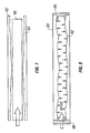
- Figures 5-8 show an example of a method by which a fiber reinforced liner for a stator may be formed.
- alternating layers of a resilient material such as an elastomer material, and a woven fiber material may be overlaid so as to form a composite structure.
- some embodiments may include wrapping successive layers over a core or mandrel.
- a mandrel is not necessary to form the liner.
- a first layer comprising an elastomer material 50 (or, for example, an elastomer tube) may be wrapped with a second layer comprising a fiber layer 52 , which in some embodiments may comprise a woven fiber mesh.
- the fiber layer 52 may comprise aramid fibers such as those sold under the mark "Kevlar” (a mark of E.I. Dupont de Nemours of Wilmington, Delaware), wherein the Kevlar fibers are wound at selected angles with respect to, for example, a longitudinal axis 54 of the liner ( e.g ., a longitudinal axis of the stator).
- Kevlar a mark of E.I. Dupont de Nemours of Wilmington, Delaware
- fibers used to reinforce the elastomer material 50 in a preferred embodiment are generally not impregnated with a resin or other polymeric material, but it is within the scope of the present invention to use impregnated materials.
- the fibers may also be wound directly onto the elastomer materials using means known in the art, and use of a pre-woven cloth is not intended to limit the scope of the invention.
- Embodiments of the invention may comprise any number of layers and arrangements of elastomer and fiber reinforcing materials.
- Figure 6 shows an embodiment comprising a fiber reinforcing layer 52 disposed between two elastomer layers 50 .
- a plurality of fiber reinforcing layers 52 may be used so as to, for example, increase a stiffness and/or wear resistance of the liner.
- the invention is not limited to the layering techniques shown in Figures 2 and 3.
- Figure 9 shows an embodiment comprising adjacent fiber layers 52 enclosed within elastomer layers 50 . This layering technique may be used to, for example, increase fiber density.
- a plurality of elastomer layers may be used to form the liner.
- a preferred embodiment comprises a plurality of consecutively layered elastomer and fiber materials.
- Fibers in the reinforcing layers may be wound at any angle with respect to the longitudinal axis of the stator.
- the fibers may be woven into a mesh, braided, or overlaid.
- a plurality of fibers may be woven together with approximately half of the fibers wound at an angle of +45 degrees and approximately half of the fibers wound at an angle of -45 degrees.
- adjacent fiber layers may be wound at similar or different angles so that, for example, one fiber layer provides circumferential support ( e.g ., a radially wound layer) and another fiber layer provides increased bending stiffness ( e.g ., a longitudinally wound layer).
- different elastomers and different fiber materials may be used in consecutive layers.
- some embodiments may comprise first 60 , second 62 , and third 64 elastomer layers enclosing first 66 and second 68 fiber layers.
- the elastomer layers 60 , 62 , 64 may comprises the same material while the first 66 and second 68 fiber layers are formed from Kevlar and glass fibers, respectively.
- different elastomer materials may be used to form the different elastomer layers 60, 62, 64 .
- Additional fiber layers may be included to, for example, form external layers that enclose the elastomer layers. Any combination of materials may be used to form the layers, and the example shown in Figure 10 is not intended to limit the scope of the invention.
- a wind angle ⁇ of selected fibers 70 may be oriented relative to lobes 72 formed on a liner 74 and shaped inner surface (not shown separately in Figure 11) of the stator (not shown separately in Figure 11).
- Figure 11 shows a planar projection of a section of the liner 74 and includes a stator axis 78 as a reference.
- contact between the rotor and the stator generally occurs in a plane 76 (e.g ., a "contact plane") that is generally defined as a function of the helical shape of the rotor and the stator.
- the fibers 70 may be wound (or a pre-woven cloth positioned) so that the fibers 70 lay at a selected angle (3 with respect to the contact plane 76 .
- the fibers 70 may be positioned so as to improve the wear and performance properties of the lobes 72 in the region proximate the seal formed between the rotor and the stator.
- the fibers 70 are shown as being positioned substantially perpendicular to the contact plane 76 . This arrangement is shown to clarify the invention and is not intended to be limiting.
- a substantially cylindrical liner 80 may be inserted into a stator 82 comprising a shaped inner surface 84 as described above.
- ends of the stator 82 may then be sealed (using, for example, end pieces 86, 88 ) and the liner 80 may be cured by applying high pressure and high temperature to the interior of the liner 80 so as to expand the liner 80 within the stator 82 so that the liner 80 may conform to the shaped inner surface 84 .
- a curing pressure, temperature, and time may be selected using means know in the art so as to completely cure the elastomer.
- the stator will be returned to normal atmospheric conditions. Final machining may be required to complete the stator (e.g., ends of the liner 80 may need to be trimmed, ends of the stator 82 may be threaded, etc. ).
- the elastomer will typically plastically deform and conform to the shaped inner surface of the stator.
- the elastomer may be selected so that, for example, the elastomer material "flows" to locally encapsulate the fiber layers and, in some embodiments, the individual fibers.
- the fiber layers may be wound or positioned in a manner that allows the fiber layers to unwrap or expand so as to conform to the expansion of the elastomer material.
- an adhesive material may also be used to bond the liner to the inner surface.
- the type of elastomer may be selected so that an adhesive is not required. If an adhesive is required, any suitable adhesive known in the art may be used in the curing process.
- a lined rotor 100 may be formed by consecutively layering elastomer layers 104 , 108 and fiber layers 106 over a rotor 102 to form a rotor liner 110.
- a plurality of elastomer and fiber layers may be used to form the rotor liner 110 , and the layers may be arranged in any manner to achieve, for example, a desired wear resistance, flexibility, stiffness, and the like.
- the rotor liner 110 may be formed according to the other methods and embodiments disclosed herein such that the arrangement shown in Figure 12 is not intended to be limiting.
- the rotor liner 110 may comprise a substantially uniform or a non-uniform cross-section, and the elastomer and fiber layers may be formed according to the description of the previous embodiments.
- the rotor liner 110 may be cured by applying high temperature and high pressure in a manner similar to that described with respect to the embodiment shown in Figure 7.
- the rotor liner 110 may be positioned on the rotor 102 before curing so that the rotor liner 110 substantially conforms to an outer surface 120 of the rotor 102 .
- the rotor liner 110 may then be cured on the rotor 102 so that the fiber and elastomer layers conform to the shape of the rotor 102 and form a bond with each other and with the outer surface 120 .
- This arrangement eliminates the need for an intermediate forming apparatus (e.g. , a mandrel) and permits the fiber reinforced rotor liner 110 to be compression molded directly onto the outer surface 120 of the rotor 102 during the curing process.
- the lined rotor 100 may be returned to atmospheric conditions and machined as required to achieve a desired final configuration.
- the lined rotor 100 is adapted for use with a stator 112 comprising a shaped, unlined inner surface 114 .
- the operation of a positive displacement motor 116 formed by the lined rotor 100 and the shaped stator 112 is similar to that described with respect to previous embodiments.
- the lined rotor 100 nutates within the shaped stator 112 , and the rotor liner 110 is compressed when lobes 118 formed on the lined rotor 100 contact the inner surface 114 of the shaped stator 112 .
- a fiber density is substantially uniform throughout the thickness of the liner.
- a uniform fiber density is advantageous because it helps achieve, for example, uniform wear resistance throughout the thickness of the liner.
- a uniform fiber density is particular desirable proximate the lobes because the lobes experience the highest mechanical and thermal stresses. Additional support and wear resistance proximate the lobes helps increase the longevity of the liner.
- the liner thickness is at a maximum proximate the lobes, and a uniform fiber density supports and helps stiffen these regions so as to reduce deformation of the lobes caused by, for example, fluid pressure and contact with the rotor.
- stator and rotor forming processes described herein enable the formation of preferred embodiments (e.g ., embodiments comprising liners having a substantially uniform fiber density) because the forming processes help ensure that a desired fiber arrangement is maintained (after the application of heat and pressure to cure the stator or rotor liner). Accordingly, the stator and rotor forming processes help avoid local and global deformation of fibers disposed in the liner such as that associated with elastomer injection around a set of prepositioned fibers in a stator tube.
- the thickness 42 of the liner 36 may be selected to generate a desired amount of contact (or, if desired, clearance) between the liner 36 and the rotor 34.
- the thickness 42 of the liner 36 may be selected to form a seal between the rotor 34 and the stator 32 while maintaining a desired level of compression between the rotor 34 and stator 32 when they are in contact with each other.
- the thickness 42 of the liner 36 may be selected to permit, for example, swelling or contraction of the liner 36 caused by elevated temperatures, contact with drilling fluids and other fluids, and the like. Similar liner thickness selections may be made when forming a fiber reinforced rotor such as that shown in Figures 12 and 13.
- the embodiment shown in Figure 4 is generally referred to as a "5:6" configuration including 5 lobes formed on the rotor and 6 lobes formed on the stator.
- the embodiment shown in Figure 13 is similarly referred to as a "4:5" configuration.
- Other embodiments may include any other rotor/stator combination known in the art, including 1:2, 3:4, 7:8, and other arrangements.
- stators may generally be formed using "n+1" or "n-1" lobes, where "n” refers to a number of rotor lobes. Accordingly, the embodiments shown in Figures 4 and 13, and other embodiments described herein, are intended to clarify the invention and are not intended to limit the scope of the invention with respect to, for example, a number of or arrangement of lobes.
- the invention comprises a stator or rotor comprising a durable liner comprising a fiber reinforced material.
- the fiber reinforced liner material may be used with conventional rotors and formed stators having a shaped inner surface, and the liner material may be adapted to form either a non-uniform or a substantially uniform liner thickness.
- the fiber density may be controlled so that it is substantially constant through a cross-section of the liner material (especially proximate lobes formed in liner having a non-uniform cross-section), and the liner material may be formed using industry standard manufacturing processes, such as calendaring, before being disposed in the stator or on the outer surface of the rotor.
- the fiber reinforced liner material helps increase the longevity of the liner and, therefore, the stator or rotor by providing additional mechanical and thermal support through the liner but especially proximate the stator or rotor lobes. Increased longevity reduces a number of trips required to replace failed power sections when drilling wells in earth formation. Accordingly, fiber reinforced stators or rotors may significantly reduce the costs associated with drilling and exploration.
Landscapes
- Engineering & Computer Science (AREA)
- Mechanical Engineering (AREA)
- Chemical & Material Sciences (AREA)
- Composite Materials (AREA)
- General Engineering & Computer Science (AREA)
- Moulding By Coating Moulds (AREA)
- Filling Or Discharging Of Gas Storage Vessels (AREA)
Abstract
Description
- The invention relates generally to stators used with positive displacement drilling motors. More specifically, the invention relates to a fiber reinforced liner adapted for use with formed stators.
- Positive Displacement Motors (PDMs) are known in the art and are commonly used to drill wells in earth formations. PDMs operate according to a reverse mechanical application of the Moineau principle wherein pressurized fluid is forced though a series of channels formed on a rotor and a stator. The channels are generally helical in shape and may extend the entire length of the rotor and stator. The passage of the pressurized fluid generally causes the rotor to rotate within the stator. For example, a substantially continuous seal may be formed between the rotor and the stator, and the pressurized fluid may act against the rotor proximate the sealing surfaces so as to impart rotational motion on the rotor as the pressurized fluid passes through the helical channels.
- Referring to Figure 1, a
typical rotor 10 includes at least one lobe 12 (wherein, for example,channels 14 are formed between lobes 12), amajor diameter 8, and aminor diameter 6. Therotor 10 may be formed of metal or any other suitable material. Therotor 10 may also be coated to withstand harsh drilling environments experienced downhole. Referring to Figure 2, atypical stator 20 comprises at least twolobes 22, amajor diameter 7, and a minor diameter 5. Note that if the rotor (10 in Figure 1) includes "n" lobes, thecorresponding stator 20 used in combination with therotor 10 generally includes either "n+1" or "n-1" lobes. Referring to Figure 3, thestator 20 generally includes a cylindricalexternal tube 24 and a liner 26. The liner 26 may be formed from an elastomer, plastic, or other synthetic or natural material known in the art. The liner 26 is typically injected into the cylindricalexternal tube 24 around a mold (not shown) that has been placed therein. The liner 26 is then cured for a selected time at a selected temperature (or temperatures) before the mold (not shown) is removed. Athickness 28 of the liner 26 is generally controlled by changing the dimensions of the mold (not shown). - A lower end of the rotor may be coupled either directly or indirectly to, for example, a drill bit. In this manner, the PDM provides a drive mechanism for a drill bit independent of any rotational motion of a drillstring generated proximate the surface of the well by, for example, rotation of a rotary table on a drilling rig. Accordingly, PDMs are especially useful in drilling directional wells where a drill bit is connected to a lower end of a bottom hole assembly (BHA). The BHA may include, for example, a PDM, a transmission assembly, a bent housing assembly, a bearing section, and the drill bit. The rotor may transmit torque to the drill bit via a drive shaft or a series of drive shafts that are operatively coupled to the rotor and to the drill bit. Therefore, when directionally drilling a wellbore, the drilling action is typically referred to as "sliding" because the drill string slides through the wellbore rather than rotating through the wellbore (as would be the case if the drill string were rotated using a rotary table) because rotary motion of the drill bit is produced by the PDM. However, directional drilling may also be performed by rotating the drill string and using the PDM, thereby increasing the available torque and drill bit rpm.
- A rotational frequency and, for example, an amount of torque generated by the rotation of the rotor within the stator may be selected by determining a number of lobes on the rotor and stator, a major and minor diameter of the rotor and stator, and the like. An assembled view of a rotor and a stator is shown in Figure 3. Rotation of the
rotor 10 within thestator 20 causes therotor 10 to nutate within thestator 20. Typically, a single nutation may be defined as when therotor 10 moves one lobe width within thestator 20. The motion of therotor 10 within thestator 20 may be defined by a circle O which defines a trajectory of a point A disposed on a rotor axis as point A moves around a stator axis B during a series of nutations. Note that an "eccentricity" e of the assembly may be defined as a distance between the rotor axis A and the stator axis B when therotor 10 andstator 20 are assembled to form a PDM. - Typical stators known in the art are formed in a manner similar to that shown in Figure 2. Specifically, an inner surface 29 of the
external tube 24 is generally cylindrical in shape and thestator lobes 22 are formed by molding an elastomer in theexternal tube 24. Problems may be encountered with thestator 20 when, for example, rotation of therotor 10 within thestator 20 shears off portions of thestator lobes 22. This process, which may be referred to as "chunking," deteriorates the seal formed between therotor 10 andstator 20 and may cause failure of the PDM. Chunking may be increased by swelling of the liner 26 or thermal fatigue. Swelling and thermal fatigue may be caused by elevated temperatures and exposure to certain drilling fluids and formation fluids, among other factors. Moreover, flexibility of the liner 26 may lead to incomplete sealing between therotor 10 andstator 20 such that available torque may be lost when the rotor compresses the stator lobe material, thereby reducing the power output of the PDM. Accordingly, there is a need for a stator design that provides increased power output and increased longevity in harsh downhole environments. - Prior attempts have been made to increase stator durability and heat conduction properties. U.S. Patent No. 6,201,681, issued to Turner, describes fibers disposed in an elastomer material that forms a stator for a helicoidal pump or motor. The fibers are generally arranged to form a two or three dimensional structure within the elastomer material. The fibers are either coated with the elastomer material as they are being woven to form a fabric layer or are formed into the desired arrangement to form a fiber skeleton. After the fiber skeleton is formed, elastomer is then injected into the stator under heat and pressure to complete the process.
- However, fiber reinforcement has presented manufacturing difficulties because it is difficult to achieve a desired fiber arrangement using injection molding techniques. Fiber reinforcement via injection molding requires additional manufacturing steps, and the manufacturing processes generally produce either a different concentration of fibers per unit volume of elastomer between the thick portions of the lobes and the thin portions (which reduces the mechanical strength of the liner) or, when fibers are disposed manually, a different number of layers must be applied in the thick portions of the lobes as compared to the thin portions.
- Accordingly, there is a need for a liner material that is more durable and is able to withstand prolonged sealing engagement between a rotor and a stator in harsh operating conditions. Moreover, there is a need for a new liner material that is adapted for use with stators that include contoured inner surfaces formed on the stator tube. The liner material should be durable and should be less susceptible to wear and, for example, thermal fatigue. The liner material should also be easy to install so as to achieve a desired fiber concentration proximate selected regions of the rotor or stator.
- In one aspect, the invention comprises a method of forming a stator for a positive displacement motor. The method comprises forming a liner including at least two resilient layers and at least one fiber layer. The at least two resilient layers are positioned so as to enclose the at least one fiber layer. The liner is positioned in a stator tube, and the stator tube comprises a shaped inner surface including at least two radially inwardly projecting lobes extending helically along a selected length of the stator tube. The liner is cured in the stator tube so that the liner conforms to the radially inwardly projecting lobes formed on the inner surface and to the helical shape of the inner surface. The curing is adapted to form a bond between the liner and the inner surface and between the at least two resilient layers and the at least one fiber layer.
- In another aspect, the invention comprises a stator for a positive displacement motor. The stator comprises a stator tube and a liner. The stator tube comprises a shaped inner surface including at least two radially inwardly projecting lobes extending helically along a selected length of the stator tube. The liner comprises at least two resilient layers and at least one fiber layer, and the at least two resilient layers are positioned so as to enclose the at least one fiber layer. The liner is disposed in the stator tube proximate the inner surface, and the liner conforms to the radially inwardly projecting lobes formed on the inner surface and to the helical shape of the inner surface.
- In another aspect, the invention comprises a positive displacement motor including a stator comprising a shaped inner surface. The inner surface comprises at least two radially inwardly projecting lobes extending helically along a selected length of the stator. A liner comprising at least two resilient layers and at least one fiber layer is disposed within the stator so that the liner conforms to the helical shape formed by the at least two radially inwardly projecting lobes. The at least two resilient layers are positioned so as to enclose the at least one fiber layer. A rotor comprises at least one radially outwardly projecting lobe extending helically along a selected length of the rotor. The rotor is disposed inside of the stator and the at least one radially outwardly projecting lobe formed on the rotor is adapted to sealingly engage the at least two radially inwardly projecting lobes formed when the liner conforms to the inner surface of the stator.
- In another aspect, the invention comprises a method of forming a rotor for a positive displacement motor. The method comprises forming a liner on a rotor by layering at least two resilient layers and at least one fiber layer on an outer surface of the rotor. The at least two resilient layers are positioned so as to enclose the at least one fiber layer, and the rotor comprises at least one radially outwardly projecting lobe extending helically along a selected length of the rotor. The liner is cured on the rotor so that the liner conforms to the at least one radially outwardly projecting lobe formed on the rotor and to the helical shape of the rotor, and the curing is adapted to form a bond between the liner and the outer surface and between the at least two resilient layers and the at least one fiber layer.
- In another aspect, the invention comprises a rotor for a positive displacement motor. The rotor comprises at least one radially outwardly projecting lobe formed on an outer surface of the rotor and extending helically along a selected length of the rotor. A liner comprising at least two resilient layers and at least one fiber layer is disposed on the rotor proximate the outer surface. The at least two resilient layers positioned so as to enclose the at least one fiber layer, and the liner conforms to the at least one radially outwardly projecting lobe formed on the outer surface and to the helical shape of the rotor.
- In another aspect, the invention comprises a positive displacement motor including a stator comprising a shaped inner surface. The inner surface comprises at least two radially inwardly projecting lobes extending helically along a selected length of the stator. A rotor comprises at least one radially outwardly projecting lobe formed on an outer surface of the rotor and extending helically along a selected length of the rotor. A liner comprising at least two resilient layers and at least one fiber layer is disposed on the external surface so that the liner conforms to the helical shape formed by the at least one radially outwardly projecting lobe. The at least two resilient layers are positioned so as to enclose the at least one fiber layer. The rotor is disposed inside of the stator and the at least one radially outwardly projecting lobe formed when the liner conforms to the outer surface of the rotor is adapted to sealingly engage the at least two radially inwardly projecting lobes formed on the stator.
- Other aspects and advantages of the invention will be apparent from the following description and the appended claims.
-
- Figure 1 shows a cross-sectional view of a prior art rotor.
- Figure 2 shows a cross-sectional view of a prior art stator.
- Figure 3 shows a cross-sectional view of an assembled positive displacement motor.
- Figure 4 shows a cross-sectional view of an embodiment of the invention.
- Figure 5 shows a perspective view of an embodiment of the invention.
- Figure 6 shows a perspective view of an embodiment of the invention.
- Figure 7 shows a cross-sectional view of an embodiment of the invention.
- Figure 8 shows a cross-sectional view of an embodiment of the invention.
- Figure 9 shows a cross-sectional view of an embodiment of the invention.
- Figure 10 shows a cross-sectional view of an embodiment of the invention.
- Figure 11 shows a cross-sectional view of an embodiment of the invention.
- Figure 12 shows a perspective view of an embodiment of the invention.
- Figure 13 shows a cross-sectional view of an embodiment of the invention.
-
- Figure 4 shows an embodiment comprising at least one aspect of the present invention. A positive displacement motor (PDM) 30 comprises a
stator 32 and a rotor 34. Thestator 32 comprises anexternal tube 38 that may be formed from, for example, steel or another material suitable for downhole use in a drilling environment. The stator also comprises aliner 36. - The
external tube 38 comprises a shapedinner surface 44 that comprises at least twolobes 46 formed thereon. Thelobes 46 are helically formed along a selected length of theexternal tube 38 so that thelobes 46 define a helical pattern along the selected length. The helical form of theinner surface 44 generally corresponds to a desired shape for stator lobes. Theliner 36 typically comprises at least twolobes 40, and athickness 42 of theliner 36 may be either uniform or non-uniform throughout a cross-section thereof. Accordingly, the embodiments shown herein comprising a non-uniform cross-section are intended to clarify the invention and should not be interpreted as limiting the scope of the invention to a non-uniform cross-section. The lobes 40 (and the liner 36) are helically formed along a selected length of theexternal tube 38 such that theliner 36 conforms to the helically shapedinner surface 44 so that the at least twolobes 46 formed on the shapedinner surface 44 correspond to thelobes 40 formed in theliner 36. Theexternal tube 38, including theinner surface 44, may be helically shaped by any means known in the art including machining, hydroforming, extrusion, and the like. Shaping of theinner surface 44 of theexternal tube 38 is described in co-pending U.S. Patent Application No. 10/056,135 filed on January 24, 2002, and assigned to the assignee of the present application. - In some embodiments, the shaped
inner surface 44 of theexternal tube 38 is adapted to provide additional support for the liner material. The shapedinner surface 44 "stiffens" theliner 36 by providing support for the liner 36 (e.g., by forming a metal backing), thereby increasing power available from the PDM. For example, shaping theinner surface 44 to form a contoured backing for theliner 36 may stiffen the liner material proximate thelobes 40 by reducing an amount by which theliner 36 may be compressed when contacted by therotor 44 so that a better seal may be formed between therotor 44 and thestator 32. Moreover, reduced flexibility increases an amount of torque required to stall the PDM. Thethickness 42 of theliner 36 is substantially uniform through a cross-section thereof. The shaped form of theinner surface 44 typically results in athinner liner 36 than is commonly used in prior art stators (such as that shown in Figure 2). Fluid pressure is less likely to deform theliner 36 and, accordingly, theliner 36 is less susceptible to deformation that could reduce the efficiency of the seal formed between the rotor 34 and stator 32 (thereby producing an additional loss in power output of the PDM 30). - The
liner 36 may be formed from different materials, including but not limited to resilient materials such as elastomers, polymers, and other synthetic or natural materials known in the art. A preferred embodiment comprises aliner 36 formed from a fiber reinforced elastomer material. However, while a preferred embodiment comprises an elastomer material as the resilient material, any suitable resilient material known in the art may be used within the scope of the invention. Accordingly, descriptions of embodiments contained herein that refer to elastomer materials are not intended to be limiting with respect to the type of resilient material. - Figures 5-8 show an example of a method by which a fiber reinforced liner for a stator may be formed. As shown in Figures 5 and 6, alternating layers of a resilient material, such as an elastomer material, and a woven fiber material may be overlaid so as to form a composite structure. Note that some embodiments may include wrapping successive layers over a core or mandrel. However, a mandrel is not necessary to form the liner. For example, a first layer comprising an elastomer material 50 (or, for example, an elastomer tube) may be wrapped with a second layer comprising a
fiber layer 52, which in some embodiments may comprise a woven fiber mesh. In some embodiments, thefiber layer 52 may comprise aramid fibers such as those sold under the mark "Kevlar" (a mark of E.I. Dupont de Nemours of Wilmington, Delaware), wherein the Kevlar fibers are wound at selected angles with respect to, for example, alongitudinal axis 54 of the liner (e.g., a longitudinal axis of the stator). - Other embodiments may comprise glass, carbon, or any other type of suitable fiber known in the art. Moreover, the fibers used to reinforce the
elastomer material 50 in a preferred embodiment are generally not impregnated with a resin or other polymeric material, but it is within the scope of the present invention to use impregnated materials. The fibers may also be wound directly onto the elastomer materials using means known in the art, and use of a pre-woven cloth is not intended to limit the scope of the invention. - Embodiments of the invention may comprise any number of layers and arrangements of elastomer and fiber reinforcing materials. Figure 6 shows an embodiment comprising a
fiber reinforcing layer 52 disposed between two elastomer layers 50. However, a plurality offiber reinforcing layers 52 may be used so as to, for example, increase a stiffness and/or wear resistance of the liner. Moreover, the invention is not limited to the layering techniques shown in Figures 2 and 3. For example, Figure 9 shows an embodiment comprising adjacent fiber layers 52 enclosed within elastomer layers 50. This layering technique may be used to, for example, increase fiber density. Additionally, a plurality of elastomer layers may be used to form the liner. A preferred embodiment comprises a plurality of consecutively layered elastomer and fiber materials. - Fibers in the reinforcing layers may be wound at any angle with respect to the longitudinal axis of the stator. In some embodiments, the fibers may be woven into a mesh, braided, or overlaid. For example, a plurality of fibers may be woven together with approximately half of the fibers wound at an angle of +45 degrees and approximately half of the fibers wound at an angle of -45 degrees. Moreover, adjacent fiber layers may be wound at similar or different angles so that, for example, one fiber layer provides circumferential support (e.g., a radially wound layer) and another fiber layer provides increased bending stiffness (e.g., a longitudinally wound layer).
- In some embodiments, different elastomers and different fiber materials may be used in consecutive layers. Referring to Figure 10, some embodiments may comprise first 60, second 62, and third 64 elastomer layers enclosing first 66 and second 68 fiber layers. In some embodiments, the elastomer layers 60, 62, 64 may comprises the same material while the first 66 and second 68 fiber layers are formed from Kevlar and glass fibers, respectively. Alternatively, different elastomer materials may be used to form the different elastomer layers 60, 62, 64. Additional fiber layers may be included to, for example, form external layers that enclose the elastomer layers. Any combination of materials may be used to form the layers, and the example shown in Figure 10 is not intended to limit the scope of the invention.
- In other embodiments such as the embodiment shown in Figure 11, a wind angle β of selected
fibers 70 may be oriented relative tolobes 72 formed on a liner 74 and shaped inner surface (not shown separately in Figure 11) of the stator (not shown separately in Figure 11). Note that Figure 11 shows a planar projection of a section of the liner 74 and includes astator axis 78 as a reference. For example, contact between the rotor and the stator generally occurs in a plane 76 (e.g., a "contact plane") that is generally defined as a function of the helical shape of the rotor and the stator. Accordingly, thefibers 70 may be wound (or a pre-woven cloth positioned) so that thefibers 70 lay at a selected angle (3 with respect to thecontact plane 76. In this manner, thefibers 70 may be positioned so as to improve the wear and performance properties of thelobes 72 in the region proximate the seal formed between the rotor and the stator. Note that thefibers 70 are shown as being positioned substantially perpendicular to thecontact plane 76. This arrangement is shown to clarify the invention and is not intended to be limiting. - Referring to Figure 7, after the layering process has been completed, a substantially
cylindrical liner 80 may be inserted into astator 82 comprising a shapedinner surface 84 as described above. Referring to Figure 8, ends of thestator 82 may then be sealed (using, for example,end pieces 86, 88) and theliner 80 may be cured by applying high pressure and high temperature to the interior of theliner 80 so as to expand theliner 80 within thestator 82 so that theliner 80 may conform to the shapedinner surface 84. A curing pressure, temperature, and time may be selected using means know in the art so as to completely cure the elastomer. After completion of the curing process, the stator will be returned to normal atmospheric conditions. Final machining may be required to complete the stator (e.g., ends of theliner 80 may need to be trimmed, ends of thestator 82 may be threaded, etc. ). - During the curing process, the elastomer will typically plastically deform and conform to the shaped inner surface of the stator. Moreover, the elastomer may be selected so that, for example, the elastomer material "flows" to locally encapsulate the fiber layers and, in some embodiments, the individual fibers. The fiber layers may be wound or positioned in a manner that allows the fiber layers to unwrap or expand so as to conform to the expansion of the elastomer material. Note that an adhesive material may also be used to bond the liner to the inner surface. However, the type of elastomer may be selected so that an adhesive is not required. If an adhesive is required, any suitable adhesive known in the art may be used in the curing process.
- Another embodiment comprising at least one aspect of the present invention is shown in Figure 12. A lined
rotor 100 may be formed by consecutively layering elastomer layers 104, 108 andfiber layers 106 over arotor 102 to form arotor liner 110. As described with respect to previous embodiments, a plurality of elastomer and fiber layers may be used to form therotor liner 110, and the layers may be arranged in any manner to achieve, for example, a desired wear resistance, flexibility, stiffness, and the like. Moreover, therotor liner 110 may be formed according to the other methods and embodiments disclosed herein such that the arrangement shown in Figure 12 is not intended to be limiting. For example, therotor liner 110 may comprise a substantially uniform or a non-uniform cross-section, and the elastomer and fiber layers may be formed according to the description of the previous embodiments. - After the
rotor 102 has been coated with the fiber reinforcedrotor liner 110, therotor liner 110 may be cured by applying high temperature and high pressure in a manner similar to that described with respect to the embodiment shown in Figure 7. Therotor liner 110 may be positioned on therotor 102 before curing so that therotor liner 110 substantially conforms to anouter surface 120 of therotor 102. Therotor liner 110 may then be cured on therotor 102 so that the fiber and elastomer layers conform to the shape of therotor 102 and form a bond with each other and with theouter surface 120. This arrangement eliminates the need for an intermediate forming apparatus (e.g., a mandrel) and permits the fiber reinforcedrotor liner 110 to be compression molded directly onto theouter surface 120 of therotor 102 during the curing process. - After completion of the curing process, the lined
rotor 100 may be returned to atmospheric conditions and machined as required to achieve a desired final configuration. Referring to Figure 13, the linedrotor 100 is adapted for use with astator 112 comprising a shaped, unlinedinner surface 114. The operation of apositive displacement motor 116 formed by the linedrotor 100 and the shapedstator 112 is similar to that described with respect to previous embodiments. The linedrotor 100 nutates within the shapedstator 112, and therotor liner 110 is compressed whenlobes 118 formed on the linedrotor 100 contact theinner surface 114 of the shapedstator 112. - In a preferred embodiment of the invention, a fiber density is substantially uniform throughout the thickness of the liner. A uniform fiber density is advantageous because it helps achieve, for example, uniform wear resistance throughout the thickness of the liner. A uniform fiber density is particular desirable proximate the lobes because the lobes experience the highest mechanical and thermal stresses. Additional support and wear resistance proximate the lobes helps increase the longevity of the liner. Note that, in some embodiments, the liner thickness is at a maximum proximate the lobes, and a uniform fiber density supports and helps stiffen these regions so as to reduce deformation of the lobes caused by, for example, fluid pressure and contact with the rotor.
- The stator and rotor forming processes described herein enable the formation of preferred embodiments (e.g., embodiments comprising liners having a substantially uniform fiber density) because the forming processes help ensure that a desired fiber arrangement is maintained (after the application of heat and pressure to cure the stator or rotor liner). Accordingly, the stator and rotor forming processes help avoid local and global deformation of fibers disposed in the liner such as that associated with elastomer injection around a set of prepositioned fibers in a stator tube.
- Referring again to Figure 4, the
thickness 42 of theliner 36 may be selected to generate a desired amount of contact (or, if desired, clearance) between theliner 36 and the rotor 34. For example, thethickness 42 of theliner 36 may be selected to form a seal between the rotor 34 and thestator 32 while maintaining a desired level of compression between the rotor 34 andstator 32 when they are in contact with each other. Moreover, thethickness 42 of theliner 36 may be selected to permit, for example, swelling or contraction of theliner 36 caused by elevated temperatures, contact with drilling fluids and other fluids, and the like. Similar liner thickness selections may be made when forming a fiber reinforced rotor such as that shown in Figures 12 and 13. - Note that the embodiment shown in Figure 4 is generally referred to as a "5:6" configuration including 5 lobes formed on the rotor and 6 lobes formed on the stator. Moreover, the embodiment shown in Figure 13 is similarly referred to as a "4:5" configuration. Other embodiments may include any other rotor/stator combination known in the art, including 1:2, 3:4, 7:8, and other arrangements. Moreover, as described above, stators may generally be formed using "n+1" or "n-1" lobes, where "n" refers to a number of rotor lobes. Accordingly, the embodiments shown in Figures 4 and 13, and other embodiments described herein, are intended to clarify the invention and are not intended to limit the scope of the invention with respect to, for example, a number of or arrangement of lobes.
- Advantageously, the invention comprises a stator or rotor comprising a durable liner comprising a fiber reinforced material. The fiber reinforced liner material may be used with conventional rotors and formed stators having a shaped inner surface, and the liner material may be adapted to form either a non-uniform or a substantially uniform liner thickness. The fiber density may be controlled so that it is substantially constant through a cross-section of the liner material (especially proximate lobes formed in liner having a non-uniform cross-section), and the liner material may be formed using industry standard manufacturing processes, such as calendaring, before being disposed in the stator or on the outer surface of the rotor.
- The fiber reinforced liner material helps increase the longevity of the liner and, therefore, the stator or rotor by providing additional mechanical and thermal support through the liner but especially proximate the stator or rotor lobes. Increased longevity reduces a number of trips required to replace failed power sections when drilling wells in earth formation. Accordingly, fiber reinforced stators or rotors may significantly reduce the costs associated with drilling and exploration.
- While the invention has been described with respect to a limited number of embodiments, those skilled in the art, having benefit of this disclosure, will appreciate that other embodiments can be devised which do not depart from the scope of the invention as disclosed herein. Accordingly, the scope of the invention should be limited only by the attached claims.
Claims (27)
Applications Claiming Priority (2)
| Application Number | Priority Date | Filing Date | Title |
|---|---|---|---|
| US97480 | 2002-03-14 | ||
| US10/097,480 US6604922B1 (en) | 2002-03-14 | 2002-03-14 | Optimized fiber reinforced liner material for positive displacement drilling motors |
Publications (2)
| Publication Number | Publication Date |
|---|---|
| EP1344936A1 true EP1344936A1 (en) | 2003-09-17 |
| EP1344936B1 EP1344936B1 (en) | 2009-10-28 |
Family
ID=27660418
Family Applications (1)
| Application Number | Title | Priority Date | Filing Date |
|---|---|---|---|
| EP03250170A Expired - Lifetime EP1344936B1 (en) | 2002-03-14 | 2003-01-10 | Fibre reinforced liner material for moineau-type motor and method of forming |
Country Status (4)
| Country | Link |
|---|---|
| US (2) | US6604922B1 (en) |
| EP (1) | EP1344936B1 (en) |
| CA (1) | CA2411989C (en) |
| DE (1) | DE60329802D1 (en) |
Cited By (1)
| Publication number | Priority date | Publication date | Assignee | Title |
|---|---|---|---|---|
| GB2424452A (en) * | 2005-03-22 | 2006-09-27 | Schlumberger Holdings | Progressive cavity motor with elastomer rotor sheath |
Families Citing this family (62)
| Publication number | Priority date | Publication date | Assignee | Title |
|---|---|---|---|---|
| US6604922B1 (en) * | 2002-03-14 | 2003-08-12 | Schlumberger Technology Corporation | Optimized fiber reinforced liner material for positive displacement drilling motors |
| EP1558847A1 (en) * | 2002-10-21 | 2005-08-03 | Noetic Engineering Inc. | Stator of a moineau-pump |
| DE10338632B4 (en) * | 2003-08-22 | 2005-11-03 | Wilhelm Kächele GmbH | Eccentric screw pump with erosion-resistant rotor |
| US20050089429A1 (en) * | 2003-10-27 | 2005-04-28 | Dyna-Drill Technologies, Inc. | Composite material progressing cavity stators |
| US20050218741A1 (en) * | 2004-03-18 | 2005-10-06 | Wnorowski Edward J Jr | Generators, transformers and stators containing high-strength, laminated, carbon-fiber windings |
| US7396220B2 (en) * | 2005-02-11 | 2008-07-08 | Dyna-Drill Technologies, Inc. | Progressing cavity stator including at least one cast longitudinal section |
| US20060182643A1 (en) * | 2005-02-11 | 2006-08-17 | Dyna-Drill Technologies, Inc. | Progressing cavity stator having a plurality of cast longitudinal sections |
| US7828533B2 (en) * | 2006-01-26 | 2010-11-09 | National-Oilwell, L.P. | Positive displacement motor/progressive cavity pump |
| DE102006018124A1 (en) | 2006-04-19 | 2007-10-25 | Schwäbische Hüttenwerke Automotive GmbH & Co. KG | Adjustable rotary pump with wear reduction |
| US20080023123A1 (en) * | 2006-07-31 | 2008-01-31 | Schlumberger Technology Corporation | Automatic elastomer extrusion apparatus and method |
| US9163629B2 (en) * | 2006-07-31 | 2015-10-20 | Schlumberger Technology Corporation | Controlled thickness resilient material lined stator and method of forming |
| US20080050259A1 (en) * | 2006-08-25 | 2008-02-28 | Dyna-Drill Technologies, Inc. | Highly reinforced elastomer for use in downhole stators |
| US7617874B2 (en) * | 2006-09-11 | 2009-11-17 | Schlumberger Technology Corporation | Flexible matrix composite actuator for use in subsurface wellbores |
| US8337182B2 (en) * | 2006-10-03 | 2012-12-25 | Schlumberger Technology Corporation | Skinning of progressive cavity apparatus |
| US8173909B2 (en) * | 2006-10-25 | 2012-05-08 | Nitto Denko Corporation | Method for mating flexure to flex-print circuit and flexure therefor |
| CA2673720C (en) | 2007-01-24 | 2013-04-16 | Halliburton Energy Services, Inc. | Electroformed stator tube for a progressing cavity apparatus |
| DE112008000606A5 (en) * | 2007-04-02 | 2009-12-10 | Luk Lamellen Und Kupplungsbau Beteiligungs Kg | friction lining |
| US8257633B2 (en) * | 2007-04-27 | 2012-09-04 | Schlumberger Technology Corporation | Rotor of progressive cavity apparatus and method of forming |
| US7950914B2 (en) * | 2007-06-05 | 2011-05-31 | Smith International, Inc. | Braze or solder reinforced Moineau stator |
| US7878774B2 (en) * | 2007-06-05 | 2011-02-01 | Smith International, Inc. | Moineau stator including a skeletal reinforcement |
| TWI467087B (en) * | 2008-03-25 | 2015-01-01 | Amicable Inv S Llc | Equipment that interacts with air or gas and its injection engine |
| US8734141B2 (en) * | 2009-09-23 | 2014-05-27 | Halliburton Energy Services, P.C. | Stator/rotor assemblies having enhanced performance |
| US20110116961A1 (en) * | 2009-11-13 | 2011-05-19 | Hossein Akbari | Stators for downhole motors, methods for fabricating the same, and downhole motors incorporating the same |
| US9347266B2 (en) | 2009-11-13 | 2016-05-24 | Schlumberger Technology Corporation | Stator inserts, methods of fabricating the same, and downhole motors incorporating the same |
| US8777598B2 (en) * | 2009-11-13 | 2014-07-15 | Schlumberger Technology Corporation | Stators for downwhole motors, methods for fabricating the same, and downhole motors incorporating the same |
| US8403332B2 (en) * | 2009-12-28 | 2013-03-26 | Nissan Kogyo Co., Ltd | Seal member |
| US8614273B2 (en) * | 2009-12-28 | 2013-12-24 | Nissin Kogyo Co., Ltd. | Seal member |
| US20110156357A1 (en) * | 2009-12-28 | 2011-06-30 | Nissin Kogyo Co., Ltd. | Dynamic seal member |
| WO2011109449A1 (en) | 2010-03-01 | 2011-09-09 | Frazier Scott R | Rotary compressor-expander systems and associated methods of use and manufacture |
| US9393648B2 (en) | 2010-03-30 | 2016-07-19 | Smith International Inc. | Undercut stator for a positive displacment motor |
| US9045943B2 (en) * | 2010-07-23 | 2015-06-02 | Baker Hughes Incorporated | Components and motors for downhole tools and methods of applying hardfacing to surfaces thereof |
| US9309884B2 (en) * | 2010-11-29 | 2016-04-12 | Schlumberger Technology Corporation | Downhole motor or pump components, method of fabrication the same, and downhole motors incorporating the same |
| US8944789B2 (en) | 2010-12-10 | 2015-02-03 | National Oilwell Varco, L.P. | Enhanced elastomeric stator insert via reinforcing agent distribution and orientation |
| US8840385B2 (en) | 2011-03-03 | 2014-09-23 | Ti Group Automotive Systems, L.L.C. | Positive displacement fluid pump |
| BR112013025421B1 (en) | 2011-04-08 | 2020-10-27 | National Oilwell Varco, L.P. | valve to control the flow of a drilling fluid, and method of controlling the flow of a drilling fluid |
| CA2839949A1 (en) | 2011-06-28 | 2013-01-03 | Bright Energy Storage Technologies, Llp | Semi-isothermal compression engines with separate combustors and expanders, and associated systems and methods |
| US9340854B2 (en) | 2011-07-13 | 2016-05-17 | Baker Hughes Incorporated | Downhole motor with diamond-like carbon coating on stator and/or rotor and method of making said downhole motor |
| US9168552B2 (en) | 2011-08-25 | 2015-10-27 | Smith International, Inc. | Spray system for application of adhesive to a stator tube |
| US20130052067A1 (en) * | 2011-08-26 | 2013-02-28 | Baker Hughes Incorporated | Downhole Motors and Pumps with Improved Stators and Methods of Making and Using Same |
| US8888474B2 (en) | 2011-09-08 | 2014-11-18 | Baker Hughes Incorporated | Downhole motors and pumps with asymmetric lobes |
| US9228584B2 (en) | 2011-11-10 | 2016-01-05 | Schlumberger Technology Corporation | Reinforced directional drilling assemblies and methods of forming same |
| CN102562574A (en) * | 2011-12-31 | 2012-07-11 | 重庆明珠机电有限公司 | Single-screw pump |
| EP2817485B1 (en) * | 2012-02-21 | 2021-05-12 | Services Pétroliers Schlumberger | Fiber reinforced elastomeric stator |
| WO2014031963A1 (en) * | 2012-08-24 | 2014-02-27 | Barson Composites Corporation | Coatings for fluid energy device components |
| US8985977B2 (en) | 2012-09-06 | 2015-03-24 | Baker Hughes Incorporated | Asymmetric lobes for motors and pumps |
| US9133841B2 (en) | 2013-04-11 | 2015-09-15 | Cameron International Corporation | Progressing cavity stator with metal plates having apertures with englarged ends |
| JP6615444B2 (en) | 2013-10-17 | 2019-12-04 | 日信工業株式会社 | Method for producing rubber composition and rubber composition |
| US20150122549A1 (en) | 2013-11-05 | 2015-05-07 | Baker Hughes Incorporated | Hydraulic tools, drilling systems including hydraulic tools, and methods of using hydraulic tools |
| BR112016019261B1 (en) | 2014-02-18 | 2022-06-14 | Reme Technologies, Llc | PROGRESSIVE CAVITY ENERGY SECTION |
| JP2017506308A (en) | 2014-02-18 | 2017-03-02 | バート ローターズ ユーケー リミテッドVert Rotors Uk Limited | Positive displacement rotary machine |
| US20150252653A1 (en) * | 2014-03-04 | 2015-09-10 | Geothermal Technologies, Inc. | System to enable geothermal field interaction with existing hvac systems, method to enable geothermal field interaction with existing hvac system |
| KR101714157B1 (en) * | 2015-06-08 | 2017-03-08 | 현대자동차주식회사 | Molding apparatus |
| WO2017095466A1 (en) * | 2015-11-30 | 2017-06-08 | Halliburton Energy Services, Inc. | Stiffness tuning and dynamic force balancing rotors of downhole drilling motors |
| US9896885B2 (en) | 2015-12-10 | 2018-02-20 | Baker Hughes Incorporated | Hydraulic tools including removable coatings, drilling systems, and methods of making and using hydraulic tools |
| CA2961629A1 (en) | 2017-03-22 | 2018-09-22 | Infocus Energy Services Inc. | Reaming systems, devices, assemblies, and related methods of use |
| US10612381B2 (en) * | 2017-05-30 | 2020-04-07 | Reme Technologies, Llc | Mud motor inverse power section |
| EP4171934A4 (en) | 2020-06-30 | 2024-07-31 | Services Pétroliers Schlumberger | Over mandrel extrusion for composite pcp stator |
| CN112123617B (en) * | 2020-07-27 | 2022-02-25 | 青岛科技大学 | A meshing shearing variable gap hexagonal rotor |
| WO2022026572A1 (en) | 2020-07-31 | 2022-02-03 | Baker Hughes Oilfield Operations Llc | Metal felt and brush structures as sealing elements in metal-metal mud motors |
| US12110892B2 (en) | 2020-08-21 | 2024-10-08 | Schlumberger Technology Corporation | System and methodology comprising composite stator for low flow electric submersible progressive cavity pump |
| CN112549346B (en) * | 2020-10-21 | 2022-02-01 | 青岛科技大学 | Variable-gap rotor for internal mixer |
| CN112976605B (en) * | 2021-02-04 | 2022-06-28 | 哈尔滨玻璃钢研究院有限公司 | Forming method of low-cost double-flanging flange structure |
Citations (8)
| Publication number | Priority date | Publication date | Assignee | Title |
|---|---|---|---|---|
| DE3119568A1 (en) * | 1981-05-16 | 1982-12-02 | Big Dutchman (International) AG, 8090 Wezep | Eccentric worm screw pump |
| DE3147663A1 (en) * | 1981-12-02 | 1983-06-09 | Gummi-Jäger KG GmbH & Cie, 3000 Hannover | Stator for spiral pumps |
| WO1999031389A2 (en) * | 1997-12-18 | 1999-06-24 | Baker Hughes Incorporated | Method of making stators for moineau pumps |
| US6102681A (en) * | 1997-10-15 | 2000-08-15 | Aps Technology | Stator especially adapted for use in a helicoidal pump/motor |
| US6201681B1 (en) | 1998-07-09 | 2001-03-13 | Honda Giken Kogyo Kabushiki Kaisha | Control apparatus for electromagnetic actuator |
| WO2001044615A2 (en) * | 1999-11-10 | 2001-06-21 | Ewm Technology, Inc. | Composite stator for drilling motors and method of constructing same |
| US20010005486A1 (en) * | 1996-04-24 | 2001-06-28 | Wood Steven M. | Progressive cavity helical device |
| WO2001081730A1 (en) * | 2000-04-21 | 2001-11-01 | Aps Technology, Inc. | Improved stator especially adapted for use in a helicoidal pump/motor and method of making same |
Family Cites Families (22)
| Publication number | Priority date | Publication date | Assignee | Title |
|---|---|---|---|---|
| US3417664A (en) | 1966-08-29 | 1968-12-24 | Black & Decker Mfg Co | Vane construction for pneumatic motor |
| FR2343906A1 (en) | 1976-03-09 | 1977-10-07 | Mecanique Metallurgie Ste Gle | IMPROVEMENTS TO SCREW PUMP STATORS |
| DE2713468C3 (en) * | 1977-03-26 | 1982-09-02 | Allweiler Ag, 7760 Radolfzell | Stator for progressing cavity pumps |
| US4173670A (en) | 1977-05-27 | 1979-11-06 | Exxon Research & Engineering Co. | Composite tubular elements |
| US4836759A (en) | 1985-11-08 | 1989-06-06 | Nautical Services Pty. Ltd. | Rotary pump with orbiting rotor of harder material than stator |
| US4676725A (en) | 1985-12-27 | 1987-06-30 | Hughes Tool Company | Moineau type gear mechanism with resilient sleeve |
| US5611397A (en) | 1994-02-14 | 1997-03-18 | Wood; Steven M. | Reverse Moineau motor and centrifugal pump assembly for producing fluids from a well |
| US6183226B1 (en) | 1986-04-24 | 2001-02-06 | Steven M. Wood | Progressive cavity motors using composite materials |
| GB2244517B (en) | 1990-05-31 | 1994-05-04 | Mono Pumps Ltd | Helical gear pump and stator |
| US5171138A (en) | 1990-12-20 | 1992-12-15 | Drilex Systems, Inc. | Composite stator construction for downhole drilling motors |
| DE4134853C1 (en) | 1991-05-22 | 1992-11-12 | Netzsch-Mohnopumpen Gmbh, 8264 Waldkraiburg, De | |
| DE4237966A1 (en) | 1992-11-11 | 1994-05-26 | Arnold Jaeger | Eccentric screw pump |
| US5759019A (en) | 1994-02-14 | 1998-06-02 | Steven M. Wood | Progressive cavity pumps using composite materials |
| DE19734678B4 (en) | 1996-08-23 | 2017-03-02 | Schaeffler Technologies AG & Co. KG | Hydrodynamic torque converter |
| JP3522062B2 (en) | 1997-01-23 | 2004-04-26 | 鬼怒川ゴム工業株式会社 | Fiber reinforced rubber hose for automatic transmission |
| DE19754818A1 (en) | 1997-12-10 | 1999-06-17 | Artemis Kautschuk Kunststoff | Process for the production of elastomer stators for eccentric screw pumps |
| DE19804259A1 (en) | 1998-02-04 | 1999-08-12 | Artemis Kautschuk Kunststoff | Elastomer stator for eccentric screw pumps |
| US6120267A (en) | 1998-04-01 | 2000-09-19 | Robbins & Myers, Inc. | Progressing cavity pump including a stator modified to improve material handling capability |
| US6309195B1 (en) | 1998-06-05 | 2001-10-30 | Halliburton Energy Services, Inc. | Internally profiled stator tube |
| DE19827101A1 (en) | 1998-06-18 | 1999-12-23 | Artemis Kautschuk Kunststoff | Machine used in deep drilling, especially in crude oil recovery |
| US6604921B1 (en) * | 2002-01-24 | 2003-08-12 | Schlumberger Technology Corporation | Optimized liner thickness for positive displacement drilling motors |
| US6604922B1 (en) * | 2002-03-14 | 2003-08-12 | Schlumberger Technology Corporation | Optimized fiber reinforced liner material for positive displacement drilling motors |
-
2002
- 2002-03-14 US US10/097,480 patent/US6604922B1/en not_active Expired - Lifetime
- 2002-11-18 CA CA002411989A patent/CA2411989C/en not_active Expired - Fee Related
-
2003
- 2003-01-10 DE DE60329802T patent/DE60329802D1/en not_active Expired - Lifetime
- 2003-01-10 EP EP03250170A patent/EP1344936B1/en not_active Expired - Lifetime
- 2003-05-15 US US10/439,210 patent/US6944935B2/en not_active Expired - Lifetime
Patent Citations (8)
| Publication number | Priority date | Publication date | Assignee | Title |
|---|---|---|---|---|
| DE3119568A1 (en) * | 1981-05-16 | 1982-12-02 | Big Dutchman (International) AG, 8090 Wezep | Eccentric worm screw pump |
| DE3147663A1 (en) * | 1981-12-02 | 1983-06-09 | Gummi-Jäger KG GmbH & Cie, 3000 Hannover | Stator for spiral pumps |
| US20010005486A1 (en) * | 1996-04-24 | 2001-06-28 | Wood Steven M. | Progressive cavity helical device |
| US6102681A (en) * | 1997-10-15 | 2000-08-15 | Aps Technology | Stator especially adapted for use in a helicoidal pump/motor |
| WO1999031389A2 (en) * | 1997-12-18 | 1999-06-24 | Baker Hughes Incorporated | Method of making stators for moineau pumps |
| US6201681B1 (en) | 1998-07-09 | 2001-03-13 | Honda Giken Kogyo Kabushiki Kaisha | Control apparatus for electromagnetic actuator |
| WO2001044615A2 (en) * | 1999-11-10 | 2001-06-21 | Ewm Technology, Inc. | Composite stator for drilling motors and method of constructing same |
| WO2001081730A1 (en) * | 2000-04-21 | 2001-11-01 | Aps Technology, Inc. | Improved stator especially adapted for use in a helicoidal pump/motor and method of making same |
Cited By (2)
| Publication number | Priority date | Publication date | Assignee | Title |
|---|---|---|---|---|
| GB2424452A (en) * | 2005-03-22 | 2006-09-27 | Schlumberger Holdings | Progressive cavity motor with elastomer rotor sheath |
| GB2424452B (en) * | 2005-03-22 | 2011-01-19 | Schlumberger Holdings | Progressive cavity motor with rotor having an elastomer sleeve |
Also Published As
| Publication number | Publication date |
|---|---|
| DE60329802D1 (en) | 2009-12-10 |
| US6944935B2 (en) | 2005-09-20 |
| CA2411989C (en) | 2006-02-07 |
| EP1344936B1 (en) | 2009-10-28 |
| CA2411989A1 (en) | 2003-09-14 |
| US20030192184A1 (en) | 2003-10-16 |
| US6604922B1 (en) | 2003-08-12 |
Similar Documents
| Publication | Publication Date | Title |
|---|---|---|
| EP1344936B1 (en) | Fibre reinforced liner material for moineau-type motor and method of forming | |
| EP1333151B1 (en) | Liner of optimized thickness for positive displacement drilling motors | |
| CA2606034C (en) | Skinning of progressive cavity apparatus | |
| US10724299B2 (en) | Reinforced directional drilling assemblies and methods of forming same | |
| EP1095218B1 (en) | Internally profiled stator tube | |
| EP0894195B1 (en) | Progressive cavity pumps using composite materials | |
| CA2397164C (en) | Progressive cavity helical device | |
| RU2607833C2 (en) | Downhole motors and pumps with asymmetric helical teeth | |
| US8734141B2 (en) | Stator/rotor assemblies having enhanced performance | |
| US7739792B2 (en) | Method of forming controlled thickness resilient material lined stator | |
| US20130052067A1 (en) | Downhole Motors and Pumps with Improved Stators and Methods of Making and Using Same | |
| US9163629B2 (en) | Controlled thickness resilient material lined stator and method of forming | |
| EP1693571B1 (en) | Multiple elastomer layer progressing cavity stators | |
| US20050089429A1 (en) | Composite material progressing cavity stators | |
| WO2005042910A2 (en) | Asymmetric contouring of elastomer liner on lobes in a moineau style power section stator | |
| US20060131079A1 (en) | Composite motor stator | |
| CA1121212A (en) | Stator for a downhole fluid operated motor and method of assembling the same | |
| EP1406016A1 (en) | Progressive cavity pumps using composite materials | |
| US20260117768A1 (en) | Intervening reinforcement lining for a mud motor | |
| US20080000083A1 (en) | Process for lining a fluid helical device stator | |
| RU226330U1 (en) | Mold for surface relief reinforcement of elastomeric teeth of the stator of a screw hydraulic machine with wear-resistant fabric | |
| WO2024147932A1 (en) | Anisotropic stator reinforcement lining | |
| US20260071621A1 (en) | Progressive cavity fluid pump and associated methods |
Legal Events
| Date | Code | Title | Description |
|---|---|---|---|
| PUAI | Public reference made under article 153(3) epc to a published international application that has entered the european phase |
Free format text: ORIGINAL CODE: 0009012 |
|
| AK | Designated contracting states |
Kind code of ref document: A1 Designated state(s): AT BE BG CH CY CZ DE DK EE ES FI FR GB GR HU IE IT LI LU MC NL PT SE SI SK TR |
|
| AX | Request for extension of the european patent |
Extension state: AL LT LV MK RO |
|
| 17P | Request for examination filed |
Effective date: 20040207 |
|
| AKX | Designation fees paid |
Designated state(s): BE DE FR GB |
|
| 17Q | First examination report despatched |
Effective date: 20040503 |
|
| GRAP | Despatch of communication of intention to grant a patent |
Free format text: ORIGINAL CODE: EPIDOSNIGR1 |
|
| GRAS | Grant fee paid |
Free format text: ORIGINAL CODE: EPIDOSNIGR3 |
|
| GRAA | (expected) grant |
Free format text: ORIGINAL CODE: 0009210 |
|
| AK | Designated contracting states |
Kind code of ref document: B1 Designated state(s): BE DE FR GB |
|
| REG | Reference to a national code |
Ref country code: GB Ref legal event code: FG4D |
|
| REF | Corresponds to: |
Ref document number: 60329802 Country of ref document: DE Date of ref document: 20091210 Kind code of ref document: P |
|
| PG25 | Lapsed in a contracting state [announced via postgrant information from national office to epo] |
Ref country code: BE Free format text: LAPSE BECAUSE OF FAILURE TO SUBMIT A TRANSLATION OF THE DESCRIPTION OR TO PAY THE FEE WITHIN THE PRESCRIBED TIME-LIMIT Effective date: 20091028 |
|
| PLBE | No opposition filed within time limit |
Free format text: ORIGINAL CODE: 0009261 |
|
| STAA | Information on the status of an ep patent application or granted ep patent |
Free format text: STATUS: NO OPPOSITION FILED WITHIN TIME LIMIT |
|
| 26N | No opposition filed |
Effective date: 20100729 |
|
| REG | Reference to a national code |
Ref country code: FR Ref legal event code: PLFP Year of fee payment: 14 |
|
| PGFP | Annual fee paid to national office [announced via postgrant information from national office to epo] |
Ref country code: FR Payment date: 20151208 Year of fee payment: 14 |
|
| PGFP | Annual fee paid to national office [announced via postgrant information from national office to epo] |
Ref country code: GB Payment date: 20160106 Year of fee payment: 14 |
|
| PGFP | Annual fee paid to national office [announced via postgrant information from national office to epo] |
Ref country code: DE Payment date: 20170331 Year of fee payment: 15 |
|
| GBPC | Gb: european patent ceased through non-payment of renewal fee |
Effective date: 20170110 |
|
| REG | Reference to a national code |
Ref country code: FR Ref legal event code: ST Effective date: 20170929 |
|
| PG25 | Lapsed in a contracting state [announced via postgrant information from national office to epo] |
Ref country code: FR Free format text: LAPSE BECAUSE OF NON-PAYMENT OF DUE FEES Effective date: 20170131 |
|
| PG25 | Lapsed in a contracting state [announced via postgrant information from national office to epo] |
Ref country code: GB Free format text: LAPSE BECAUSE OF NON-PAYMENT OF DUE FEES Effective date: 20170110 |
|
| REG | Reference to a national code |
Ref country code: DE Ref legal event code: R119 Ref document number: 60329802 Country of ref document: DE |
|
| PG25 | Lapsed in a contracting state [announced via postgrant information from national office to epo] |
Ref country code: DE Free format text: LAPSE BECAUSE OF NON-PAYMENT OF DUE FEES Effective date: 20180801 |
|
| P01 | Opt-out of the competence of the unified patent court (upc) registered |
Effective date: 20231208 |