EP1344915A2 - A variable position intake for an aircraft mounted gas turbine engine - Google Patents
A variable position intake for an aircraft mounted gas turbine engine Download PDFInfo
- Publication number
- EP1344915A2 EP1344915A2 EP03251232A EP03251232A EP1344915A2 EP 1344915 A2 EP1344915 A2 EP 1344915A2 EP 03251232 A EP03251232 A EP 03251232A EP 03251232 A EP03251232 A EP 03251232A EP 1344915 A2 EP1344915 A2 EP 1344915A2
- Authority
- EP
- European Patent Office
- Prior art keywords
- aircraft
- gas turbine
- wing
- turbine engine
- hollow member
- Prior art date
- Legal status (The legal status is an assumption and is not a legal conclusion. Google has not performed a legal analysis and makes no representation as to the accuracy of the status listed.)
- Granted
Links
- 230000002093 peripheral effect Effects 0.000 claims description 7
- 238000011144 upstream manufacturing Methods 0.000 description 17
- 238000002485 combustion reaction Methods 0.000 description 2
- 239000000203 mixture Substances 0.000 description 2
- 230000037406 food intake Effects 0.000 description 1
- 230000007704 transition Effects 0.000 description 1
Images


Classifications
-
- F—MECHANICAL ENGINEERING; LIGHTING; HEATING; WEAPONS; BLASTING
- F02—COMBUSTION ENGINES; HOT-GAS OR COMBUSTION-PRODUCT ENGINE PLANTS
- F02C—GAS-TURBINE PLANTS; AIR INTAKES FOR JET-PROPULSION PLANTS; CONTROLLING FUEL SUPPLY IN AIR-BREATHING JET-PROPULSION PLANTS
- F02C7/00—Features, components parts, details or accessories, not provided for in, or of interest apart form groups F02C1/00 - F02C6/00; Air intakes for jet-propulsion plants
- F02C7/04—Air intakes for gas-turbine plants or jet-propulsion plants
- F02C7/042—Air intakes for gas-turbine plants or jet-propulsion plants having variable geometry
-
- B—PERFORMING OPERATIONS; TRANSPORTING
- B64—AIRCRAFT; AVIATION; COSMONAUTICS
- B64D—EQUIPMENT FOR FITTING IN OR TO AIRCRAFT; FLIGHT SUITS; PARACHUTES; ARRANGEMENT OR MOUNTING OF POWER PLANTS OR PROPULSION TRANSMISSIONS IN AIRCRAFT
- B64D33/00—Arrangement in aircraft of power plant parts or auxiliaries not otherwise provided for
- B64D33/02—Arrangement in aircraft of power plant parts or auxiliaries not otherwise provided for of combustion air intakes
-
- F—MECHANICAL ENGINEERING; LIGHTING; HEATING; WEAPONS; BLASTING
- F05—INDEXING SCHEMES RELATING TO ENGINES OR PUMPS IN VARIOUS SUBCLASSES OF CLASSES F01-F04
- F05D—INDEXING SCHEME FOR ASPECTS RELATING TO NON-POSITIVE-DISPLACEMENT MACHINES OR ENGINES, GAS-TURBINES OR JET-PROPULSION PLANTS
- F05D2250/00—Geometry
- F05D2250/30—Arrangement of components
- F05D2250/31—Arrangement of components according to the direction of their main axis or their axis of rotation
- F05D2250/311—Arrangement of components according to the direction of their main axis or their axis of rotation the axes being in line
-
- F—MECHANICAL ENGINEERING; LIGHTING; HEATING; WEAPONS; BLASTING
- F05—INDEXING SCHEMES RELATING TO ENGINES OR PUMPS IN VARIOUS SUBCLASSES OF CLASSES F01-F04
- F05D—INDEXING SCHEME FOR ASPECTS RELATING TO NON-POSITIVE-DISPLACEMENT MACHINES OR ENGINES, GAS-TURBINES OR JET-PROPULSION PLANTS
- F05D2250/00—Geometry
- F05D2250/40—Movement of components
- F05D2250/41—Movement of components with one degree of freedom
- F05D2250/411—Movement of components with one degree of freedom in rotation
Definitions
- the present invention relates to a variable position intake for an aircraft mounted gas turbine engine.
- the present invention relates in particular to a variable position intake for an aircraft mounted turbofan gas turbine engine.
- An aircraft mounted gas turbine engine requires an intake to provide a smooth path for the flow of air into the gas turbine engine.
- the main requirement of the intake is to supply air to the gas turbine engine, under all operating conditions, with minimum loss of energy.
- the air must be supplied to the gas turbine engine fan and/or compressor at uniform pressure distributed evenly across the whole of the intake area.
- the airflow velocity into the gas turbine engine is slower than the speed of the aircraft.
- the lift provided by the aircraft wing helps to reduce the velocity of the air entering the gas turbine engine because of the higher pressure under the aircraft wing, which slows down the air flow in front of the intake mounted under and at the downstream end of the aircraft wing.
- An intake mounted under and at the downstream end of the aircraft wing interacts favourably with the aircraft wing at high-speed cruise conditions.
- the intake mounted under and at the downstream end of the aircraft wing requires a relatively small area inlet with relatively sharp lips to reduce spillage drag.
- the airflow velocity into the gas turbine engine is faster than the speed of the aircraft.
- the lift provided by the aircraft wing helps to increase the velocity of the air entering the gas turbine engine because of the lower pressure over the aircraft wing, which speeds up the air flow in front of the intake mounted over and at the downstream end of the aircraft wing.
- An intake mounted over and at the downstream end of the aircraft wing interacts favourably with the aircraft wing at low-speed conditions.
- the intake mounted over and at the downstream end of the aircraft wing requires a relatively large area inlet with relatively thick lips to guide the air into the gas turbine engine at very low speeds.
- a typical prior art solution to the problem provides an intake configured for cruise and auxiliary intakes for low speed operation and additional blocker doors to prevent foreign objects entering the intake.
- This prior art compromises the aerodynamic flow conditions into the fan and/or the compressor, which may induce aerodynamic instability and unacceptable stresses into components of the gas turbine engine.
- the present invention seeks to provide a novel intake for an aircraft mounted gas turbine engine, which reduces, preferably overcomes, the above-mentioned problems.
- the present invention provides an aircraft comprising a wing having an upper surface and a lower surface, at least one gas turbine engine mounted on the aircraft, the at least one gas turbine engine having an inlet, an intake for supplying air to the inlet of the at least one gas turbine engine, the intake comprising a movable hollow member such that in use the hollow member is movable between a first position in which air flowing over and/or above the upper surface of the wing flows through the hollow member and into the inlet of the at least one gas turbine engine and a second position in which air flowing along and/or under the lower surface of the wing flows through the hollow member and into the inlet of the at least one gas turbine engine.
- the intake comprising a hollow member rotatably mounted coaxially with the at least one gas turbine engine such that in use the hollow member is rotatable between a first position in which air flowing over and/or above the upper surface of the wing flows through the hollow member and into the inlet of the at least one gas turbine engine and a second position in which air flowing along and/or under the lower surface of the wing flows through the hollow member and into the inlet of the at least one gas turbine engine.
- the hollow member has a cylindrical base portion.
- the hollow member may be a hollow pseudo axis-symmetrical member.
- the hollow member is a hollow pseudo conical member, the hollow pseudo conical member has an aperture in one region and an aperture in the cylindrical base portion of the hollow pseudo conical member.
- the hollow member is a hollow pseudo part elliptical member, the hollow pseudo elliptical member has an aperture in one region and an aperture in the cylindrical base portion of the hollow pseudo elliptical member.
- the hollow member may have an outwardly flared portion, the hollow has an aperture in one region and an aperture in the cylindrical base portion of the hollow member.
- the aperture in the region of the hollow member has rounded edges.
- the hollow member is rotatably mounted on the gas turbine engine.
- the base portion of the hollow member is rotatably mounted on the gas turbine engine by a bearing.
- the hollow member is rotatably mounted on the wing of the aircraft.
- the hollow member is rotatably mounted on the wing of the aircraft by a bearing.
- the bearing is a roller bearing or a ball bearing.
- the intake duct comprises an intake duct portion under the lower surface of the wing.
- the intake duct portion is defined by the lower surface of the wing and a wall positioned under the lower surface of the wing.
- the wing has an aperture
- the hollow member is rotatably mounted in the aperture in the wing.
- the hollow member may have at least one groove on its outer surface.
- the present invention also provides an aircraft comprising a wing having an upper surface and a lower surface, at least one gas turbine engine mounted on the aircraft, the axis of the at least one gas turbine engine being arranged substantially in the plane of the wing of the aircraft, the at least one gas turbine engine having an inlet, an intake for supplying air to the inlet of the at least one gas turbine engine, the intake comprising a hollow member rotatably mounted coaxially with the at least one gas turbine engine such that in use the hollow member is rotatable between a first position in which air flowing over and/or above the upper surface of the wing flows through the hollow member and into the inlet of the at least one gas turbine engine and a second position in which air flowing along and/or under the lower surface of the wing flows through the hollow member and into the inlet of the at least one gas turbine engine.
- the present invention also provides a gas turbine engine having an inlet and an intake for supplying air to the inlet, the intake comprising a movable hollow member such that in use the hollow member is movable between a first position in which air flowing over a first sector upstream of the intake flows through the hollow member and into the inlet of the at least one gas turbine engine and a second position in which air flowing over a second angularly spaced sector upstream of the intake flows through the hollow member and into the inlet of the at least one gas turbine engine.
- the intake comprising a hollow member rotatably mounted coaxially with the at least one gas turbine engine such that in use the hollow member is rotatable between a first position in which air flowing over a first sector upstream of the intake flows through the hollow member and into the inlet of the at least one gas turbine engine and a second position in which air flowing over a second angularly spaced sector upstream of the intake flows through the hollow member and into the inlet of the at least one gas turbine engine.
- the hollow member has a cylindrical base portion.
- the hollow member may be a hollow pseudo axis-symmetrical member.
- the hollow member is a hollow pseudo conical member, the hollow pseudo conical member has an aperture in one region and an aperture in the cylindrical base portion of the hollow pseudo conical member.
- the hollow member is a hollow pseudo part elliptical member, the hollow pseudo elliptical member has an aperture in one region and an aperture in the cylindrical base portion of the hollow pseudo elliptical member.
- the hollow member has an outwardly flared portion, the hollow has an aperture in one region and an aperture in the cylindrical base portion of the hollow member.
- the aperture in the region of the hollow member has rounded edges.
- the hollow member is rotatably mounted on the gas turbine engine.
- the base portion of the hollow member is rotatably mounted on the gas turbine engine by a bearing.
- the bearing is a roller bearing or a ball bearing.
- the hollow member has at least one groove on its outer surface.
- the hollow member is rotated through 180° between the first position and the second position.
- the gas turbine engine is a turbofan gas turbine engine.
- the present invention also provides a gas turbine engine having an inlet and an intake for supplying air to the inlet, the intake comprising a hollow member rotatably mounted coaxially with the at least one gas turbine engine such that in use the hollow member is rotatable between a first position in which air flowing over a first sector upstream of the intake flows through the hollow member and into the inlet of the at least one gas turbine engine and a second position in which air flowing over a second angularly spaced sector upstream of the intake flows through the hollow member and into the inlet of the at least one gas turbine engine.
- FIG. 1 An aircraft 10 comprising a fuselage 11, and a pair of wings 12 is shown in figure 1.
- the wings 12 have a centre line 14, an upper surface 16 and a lower surface 18.
- the aircraft 10 has a plurality of turbofan gas turbine engines 20 mounted on the wings 12 of the aircraft 10 or on the fuselage 11 of the aircraft 10.
- Each turbofan gas turbine engine 20 comprises in flow series an inlet 22, a fan section 24, a compressor section 26, a combustion section 28, a turbine section 30 and an exhaust 32.
- the turbofan gas turbine engine 20 has an axis of rotation 34. The operation of the turbofan gas turbine engine 20 is quite conventional and its operation will not be discussed further.
- Each turbofan gas turbine engine 20 is mounted on a respective wing 12 of the aircraft 10 such that the axis 34 of the turbofan gas turbine engine 20 is substantially in the centre line 14, or plane, of the respective wing 12. Additionally the inlet 22 of each turbofan gas turbine engine 20 is positioned towards the downstream end of the respective wing 12.
- each turbofan gas turbine engine 10 has a main intake duct 36 positioned under the respective wing 12 of the aircraft 10.
- the main intake duct 36 has an intake plane 38 positioned at a mid region of the wing 12.
- the main intake duct 36 is defined by a peripheral wall 40 and in this example the main intake duct is circular in cross-section.
- the peripheral wall 40 of the main intake duct 40 is spaced from the lower surface 18 of the wing 12 at the intake plane 38 but the peripheral wall 40 blends into the lower surface 18 of the wing 12 at a suitable distance downstream of the intake plane 38.
- the wing 12 of the aircraft 10 has a symmetrically shaped, in this example a substantially triangular shaped, aperture 42 arranged immediately upstream of the inlet 22 of the turbofan 20.
- the line of symmetry of the symmetrically shaped aperture 42 is collinear with the axis 34 of the turbofan gas turbine engine 20.
- a hollow pseudo axis-symmetrical member, in this example a hollow pseudo substantially conical member, 44 is arranged immediately upstream of the inlet 22 of the turbofan 20 and the hollow pseudo conical member 44 is arranged in the aperture 42 in the wing 12 of the aircraft 10.
- the axis of symmetry of the hollow pseudo conical member 44 is arranged collinear with the line of symmetry of the aperture 42 and collinear with the axis 34 of the turbofan gas turbine engine 20.
- the hollow pseudo conical member 44 comprises a circular base portion 46 and an apex 48.
- the circular base portion 46 has a circular aperture 47 and the circular base portion 46 is rotatably mounted on the upstream end of the turbofan gas turbine engine 20 by a bearing 50.
- the apex 48 of the hollow pseudo conical member 44 is rotatably mounted on the wing 12 of the aircraft 10 by a bearing 52.
- the hollow pseudo conical member 44 also comprises an aperture 54 and one or more longitudinally extending grooves 56 on the outer surface of the hollow pseudo conical member 44.
- the two dimensional shape of the hollow pseudo conical member 44 is substantially the two dimensional shape of the aperture 42 in the wing 12 and that the dimensions of the hollow pseudo conical member 44 are substantially the same as those of the aperture 42 in the wing 12 of the aircraft 10 such that there is substantially no, or a minimum amount of, leakage of air through the aperture 42 between the hollow pseudo conical member 44 and the edge of the aperture 42.
- the means 59 may also comprise any suitable actuation means for example a pneumatic ram, a hydraulic ram, an electrical ram, a screw jack or a worm drive.
- the hollow pseudo conical member 44 In use the hollow pseudo conical member 44 is positioned in the first position, as shown in figures 2 and 3, for operation of the aircraft 10 at low-speeds and on the ground and in use the hollow pseudo conical member 44 is positioned in the second position, as shown in figures 5 and 6, for operation of the aircraft 10 at cruise and high speeds.
- Figure 4 shows the hollow pseudo conical member 44 at a position between the first position and the second position.
- the aperture 54 is aligned with the aperture 42 in the wing 12 of the aircraft 10 and allows air flowing over and/or above the upper surface 16 of the wing 12 to flow smoothly into the hollow pseudo conical member 44 though the aperture 47 and thence to the inlet 22 of the turbofan gas turbine engine 20.
- the aperture 54 of the hollow pseudo conical member 44 has rounded edges 58, which define generously proportioned intake lips for a relatively large intake over the upper surface 16 of the wing 12 of the aircraft 10.
- the hollow pseudo conical member 44 prevents the air flowing along and/or below the lower surface 18 of the wing 12 and through the intake duct 36 to the inlet 22 of the turbofan gas turbine engine 20. Any foreign objects, or debris, entering the intake duct 36 flow through the grooves 56 and out of the intake duct 36, to prevent damage to the turbofan gas turbine engine 20.
- the aperture 54 is aligned with the aperture 42 in the wing 12 of the aircraft 10 and allows air flowing below the lower surface 16 of the wing 12 to flow smoothly into the hollow pseudo conical member 44 through the aperture 47 and thence to the inlet 22 of the turbofan gas turbine engine 20.
- the hollow pseudo conical member 44 defines a sealed intake for air flowing from the intake duct 36 to the inlet 22 of the gas turbine engine 20 and hence the hollow pseudo conical member 44 prevents the air flowing over and/or above the upper surface 18 of the wing 12 to the inlet 22 of the turbofan gas turbine engine 20.
- each turbofan gas turbine engine 20 comprises in flow series an inlet 22, a fan section 24, a compressor section 26, a combustion section 28, a turbine section 30 and an exhaust 32.
- the turbofan gas turbine engine 20 has an axis of rotation 34. The operation of the turbofan gas turbine engine 20 is quite conventional and its operation will not be discussed further.
- Each turbofan gas turbine engine 20 is mounted on a respective side of the fuselage 11 of the aircraft 10 such that the axis 34 of the turbofan gas turbine engine 20 is substantially in the centre line 14, or plane, of the respective wing 12. Additionally the inlet 22 of each turbofan gas turbine engine 20 is positioned towards the downstream end of the respective wing 12.
- each turbofan gas turbine engine 10 has a main intake duct 36 positioned under the respective wing 12 of the aircraft 10.
- the main intake duct 36 has an intake plane 38 positioned at a mid region of the wing 12.
- the main intake duct 36 is defined by a peripheral wall 40 and in this example the main intake duct is circular in cross-section.
- the peripheral wall 40 of the main intake duct 40 is spaced from the lower surface 18 of the wing 12 at the intake plane 38 but the peripheral wall 40 blends into the lower surface 18 of the wing 12 at a suitable distance downstream of the intake plane 38.
- the wing 12 of the aircraft 10 has a symmetrically shaped, in this example a triangular shaped, aperture 42B arranged immediately upstream of the inlet 22 of the turbofan 20.
- the aperture 42B also comprises two notches 43B extending from the triangular shaped aperture 42B.
- the line of symmetry of the symmetrically shaped aperture 42B is collinear with the axis 34 of the turbofan gas turbine engine 20.
- a hollow member 44B is arranged immediately upstream of the inlet 22 of the turbofan 20 and the hollow member 44B is arranged in the aperture 42 in the wing 12 of the aircraft 10.
- the axis of symmetry of the hollow member 44B is arranged collinear with the line of symmetry of the aperture 42B and collinear with the axis 34 of the turbofan gas turbine engine 20.
- the hollow member 44B comprises a circular base portion 46B and an apex 48B.
- the circular base portion 46B has a circular aperture 47B and the circular base portion 46B is rotatably mounted on the upstream end of the turbofan gas turbine engine 20 by a bearing 50B.
- the apex 48B of the hollow member 44B is rotatably mounted on the wing 12 of the aircraft 10 by a bearing 52B.
- the hollow member 44B comprises an aperture 54B and an outwardly flared portion 45B.
- the hollow member 44B also has projections 45B of substantially the same shape and size as the notches 43B.
- the two dimensional shape of the hollow member 44B is substantially the two dimensional shape of the aperture 42B in the wing 12 and that the dimensions of the hollow member 44B are substantially the same as those of the aperture 42B in the wing 12 of the aircraft 10 such that there is substantially no, or a minimum amount of, leakage of air through the aperture 42B between the hollow member 44B and the edge of the aperture 42B.
- the means 59B to rotate the hollow pseudo conical member 44B through 180° between a first position and a second position.
- the means 59B comprises a toothed rack 60 on the hollow pseudo conical member 44 and a pinion gear 62 meshing with the toothed rack 60. Rotation of the pinion gear 62 causes the toothed rack 60 and hollow pseudo conical member to rotate between the first position and the second position.
- the means 59B may also comprise any suitable actuation means for example a pneumatic ram, a hydraulic ram, an electrical ram, a screw jack or a worm drive.
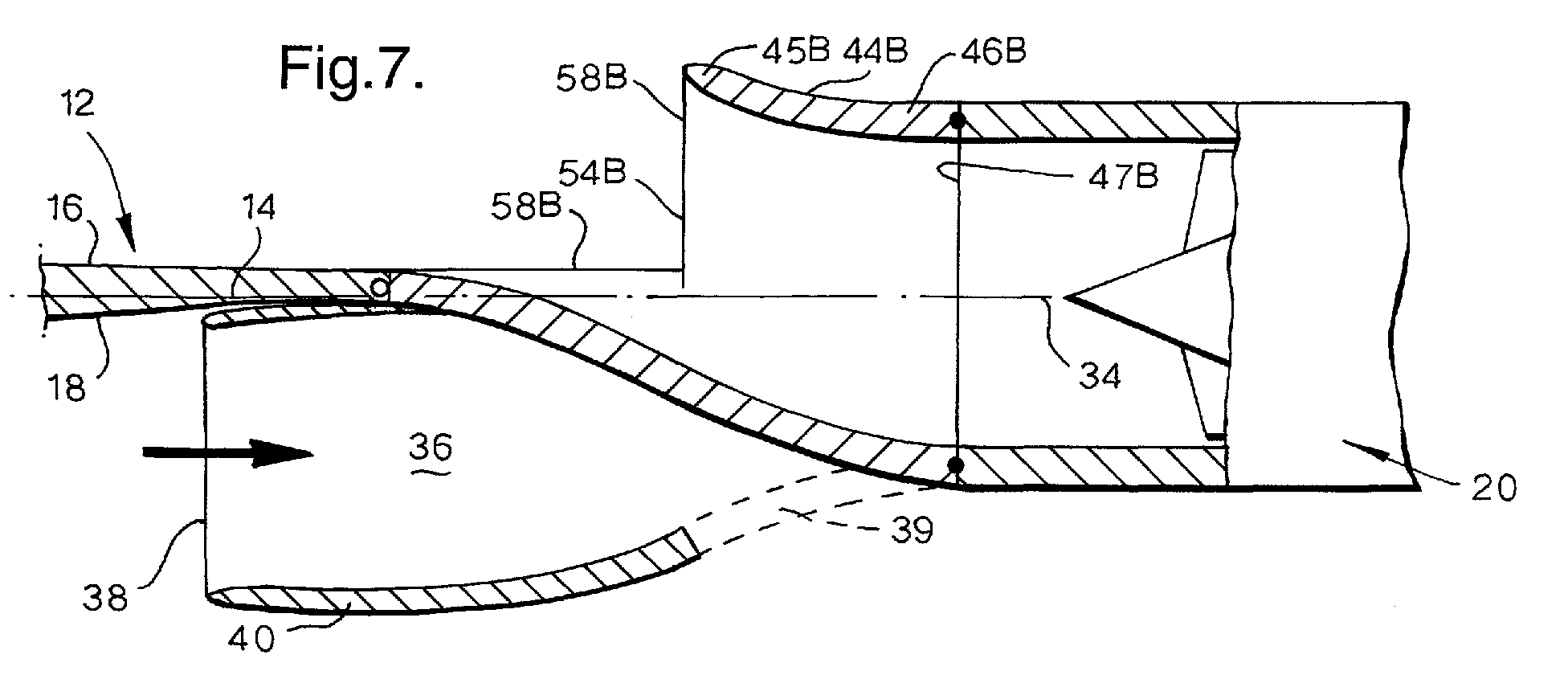
- the hollow member 44B In use the hollow member 44B is positioned in the first position, as shown in figures 7 and 8, for operation of the aircraft 10 at low-speeds and on the ground and in use the hollow member 44B is positioned in the second position, as shown in figures 9 and 10, for operation of the aircraft 10 at cruise and high speeds.
- the aperture 54B is aligned with the aperture 42B in the wing 12 of the aircraft 10 and allows air flowing over and/or above the upper surface 16 of the wing 12 to flow smoothly into the hollow member 44B through the aperture 47B and thence to the inlet 22 of the turbofan gas turbine engine 20.
- the outwardly flared portion 45B and the aperture 54B of the member 44B have rounded edges 58B which define a generously proportioned intake lips for a relatively large intake over the upper surface 16 of the wing 12 of the aircraft 10.
- the hollow member 44B prevents the air flowing along and/or below the lower surface 18 of the wing 12 and through the intake duct 36 to the inlet 22 of the turbofan gas turbine engine 20.
- any foreign objects, or debris, entering the intake duct 36 flow through the open end 39 and out of the intake duct 36, to prevent damage to the turbofan gas turbine engine 20. Additionally the open end 39 allows a flow of air through the intake duct 36 during low-speed operation of the aircraft 10 to minimise the drag penalty of the intake duct 36 in the low-speed operation of the aircraft 10.
- the aperture 54B is aligned with the aperture 42 in the wing 12 of the aircraft 10 and allows air flowing along and/or below the lower surface 16 of the wing 12 to flow smoothly through the intake duct 36, into the hollow member 44B through the aperture 47B and thence to the inlet 22 of the turbofan gas turbine engine 20.
- the outwardly flared portion 45B of the hollow member 44B is aligned with and forms a continuation of the wall 38 of the intake duct 36.
- the hollow pseudo conical member 44B defines a sealed intake for air flowing from the intake duct 36 to the inlet 22 of the gas turbine engine 20 and hence the hollow member 44B prevents the air flowing over and above the upper surface 18 of the wing 12 to the inlet 22 of the turbofan gas turbine engine 20.
- the notches 43 are provided in the aperture 42 to allow the outwardly flared portion 45B of the hollow member 44B to be rotated.
- Figures 11 and 12 show alternative perspective views to figures 8 and 10 respectively.
- the trailing edge 13 of the wing 12 has a step 15 and the gas turbine engine 20 is located at the step 15 in the trailing edge 13 of the wing 12, such that the inlet 22 is located downstream of the trailing edge 13 of the wing 12.
- the intake plane 38 is located upstream of the trailing edge 13 of the wing 12 and the hollow member 44C is located in a space 42C between the trailing edge 13 of the wing 12 and a cut out 42D in the trailing edge 13 of the wing 12.
- the step 15 in the trailing edge 13 of the wing 12 also allows the hollow member 44C to rotate around one side of the turbofan gas turbine engine 20, so that the notches are not required, to allow movement of the hollow member 44C between the first position and the second position.
- the hollow member may also comprise a hollow pseudo elliptical member, which has an aperture in one region and an aperture at the base portion of the hollow pseudo conical member.
- the hollow member 44, 44B, 44C is rotatable between a first position in which air flowing over a first sector, or first upper half, upstream of the intake flows into the inlet 22 of the turbofan gas turbine engine 20 and a second position in which air flowing over a second angularly spaced sector, or second lower half, upstream of the intake flows into the inlet 22 of the turbofan gas turbine engine 20.
- the present invention provides an aircraft mounted turbofan gas turbine engine with a nearly optimum over wing intake for low-speed and/or ground operation and a nearly optimum under wing intake for high-speed and/or cruise operation.
- the present invention has been described with reference to an intake at a mid region of the wing, it may be at a downstream region of the wing or any other suitable position of the wing as long as there is a portion of the wing upstream of the intake.
- the present invention has been described with reference to an inlet at a downstream region of the wing, it may be at a mid region of the wing or any other suitable position of the wing as long as there is a portion of the wing upstream of the inlet.
- One or more of the gas turbine engines on the aircraft may have intake ducts comprising hollow members according to the present invention.
Landscapes
- Engineering & Computer Science (AREA)
- Chemical & Material Sciences (AREA)
- Combustion & Propulsion (AREA)
- Aviation & Aerospace Engineering (AREA)
- Physics & Mathematics (AREA)
- Geometry (AREA)
- Mechanical Engineering (AREA)
- General Engineering & Computer Science (AREA)
- Structures Of Non-Positive Displacement Pumps (AREA)
Abstract
Description
Claims (19)
- An aircraft (10) comprising a wing (12) having an upper surface (16) and a lower surface (18), at least one gas turbine engine (20) mounted on the aircraft (10), the at least one gas turbine engine (20) having an inlet, an intake (36) for supplying air to the inlet (22) of the at least one gas turbine engine (20), characterised in that the intake (36) comprising a movable hollow member such that in use the hollow member (44) is movable between a first position in which air flowing over and/or above the upper surface (16) of the wing (12) flows through the hollow member (44) and into the inlet (22) of the at least one gas turbine engine (20) and a second position in which air flowing along and/or under the lower surface (18) of the wing (12) flows through the hollow member (44) and into the inlet (22) of the at least one gas turbine engine (20).
- An aircraft as claimed in claim 1 wherein the axis (34) of the at least one gas turbine engine (10) being arranged substantially in the plane (14) of the wing (12) of the aircraft (10), the intake comprising a hollow member (44) rotatably mounted coaxially with the at least one gas turbine engine (20) such that in use the hollow member (44) is rotatable between a first position in which air flowing over and/or above the upper surface (16) of the wing (12) flows through the hollow member (44) and into the inlet (22) of the at least one gas turbine engine (20) and a second position in which air flowing along and/or under the lower surface (18) of the wing (12) flows through the hollow member (44) and into the inlet (22) of the at least one gas turbine engine (20).
- An aircraft as claimed in claim 2 wherein the hollow member (44) has a cylindrical base portion (46).
- An aircraft as claimed in claim 3 wherein the hollow member (44) is a hollow pseudo axis-symmetrical member.
- An aircraft as claimed in claim 4 wherein the hollow member (44) is a hollow pseudo conical member, the hollow pseudo conical member has an aperture (54) in one region and an aperture (47) in the cylindrical base portion (46) of the hollow pseudo conical member.
- An aircraft as claimed in claim 4 wherein the hollow member (44) is a hollow pseudo part elliptical member, the hollow pseudo elliptical member has an aperture in one region and an aperture in the cylindrical base portion of the hollow pseudo elliptical member.
- An aircraft as claimed in claim 3 wherein the hollow member (44B) has an outwardly flared portion (45B), the hollow member (44B) has an aperture (54B) in one region and an aperture (47B) in the cylindrical base portion (46B) of the hollow member (44B).
- An aircraft as claimed in any of claims 5 to 7 wherein the aperture (47,47B) in the region of the hollow member (44,44B) has rounded edges (58,58B).
- An aircraft as claimed in any of claims 2 to 8 wherein the hollow member (44,44B) is rotatably mounted on the gas turbine engine (20).
- An aircraft as claimed in claim 3 wherein the base portion (46) of the hollow member (44) is rotatably mounted on the gas turbine (20) engine by a bearing (50).
- An aircraft as claimed in any of claims 2 to 9 wherein the hollow member (44,44B) is rotatably mounted on the wing (12) of the aircraft (16).
- An aircraft as claimed in claim 11 wherein the hollow member (44,44B) is rotatably mounted on the wing (12) of the aircraft (10) by a bearing (52).
- An aircraft as claimed in claim 10 or claim 12 wherein the bearing (50,52) is a roller bearing or a ball bearing.
- An aircraft as claimed in any of claims 1 to 13 wherein the intake (36) comprises an intake duct portion (36) under the lower surface (18) of the wing (12).
- An aircraft as claimed in claim 14 wherein the intake duct portion (36) is defined by a peripheral wall (40) spaced from the lower surface (18) of the wing (10).
- An aircraft as claimed in any of claims 2 to 15 wherein the wing (12) has an aperture (42), the hollow member (44,44B) is rotatably mounted in the aperture (42,42B) in the wing (12).
- An aircraft as claimed in any of claims 2 to 16 wherein the hollow member (44,44B) has at least one groove (56) on its outer surface.
- An aircraft as claimed in any of claims 2 to 17 wherein the hollow member (44,44B) is rotated through 180° between the first position and the second position.
- An aircraft as claimed in any of claims 1 to 18 wherein each of the gas turbine engines (20) has a movable hollow member (44,44B).
Applications Claiming Priority (2)
| Application Number | Priority Date | Filing Date | Title |
|---|---|---|---|
| GB0206139 | 2002-03-15 | ||
| GBGB0206139.8A GB0206139D0 (en) | 2002-03-15 | 2002-03-15 | A variable position intake for an aircraft mounted gas turbine engine |
Publications (3)
| Publication Number | Publication Date |
|---|---|
| EP1344915A2 true EP1344915A2 (en) | 2003-09-17 |
| EP1344915A3 EP1344915A3 (en) | 2005-01-12 |
| EP1344915B1 EP1344915B1 (en) | 2007-06-13 |
Family
ID=9933040
Family Applications (1)
| Application Number | Title | Priority Date | Filing Date |
|---|---|---|---|
| EP03251232A Expired - Lifetime EP1344915B1 (en) | 2002-03-15 | 2003-02-28 | A variable position intake for an aircraft mounted gas turbine engine |
Country Status (4)
| Country | Link |
|---|---|
| US (2) | US6945494B2 (en) |
| EP (1) | EP1344915B1 (en) |
| DE (1) | DE60314312T2 (en) |
| GB (1) | GB0206139D0 (en) |
Cited By (1)
| Publication number | Priority date | Publication date | Assignee | Title |
|---|---|---|---|---|
| FR2938824A1 (en) * | 2008-11-26 | 2010-05-28 | Aircelle Sa | NACELLE INTEGRATED ON FLYING WING |
Families Citing this family (26)
| Publication number | Priority date | Publication date | Assignee | Title |
|---|---|---|---|---|
| US5774870A (en) * | 1995-12-14 | 1998-06-30 | Netcentives, Inc. | Fully integrated, on-line interactive frequency and award redemption program |
| CA2314517A1 (en) | 1999-07-26 | 2001-01-26 | Gust H. Bardy | System and method for determining a reference baseline of individual patient status for use in an automated collection and analysis patient care system |
| US6221011B1 (en) | 1999-07-26 | 2001-04-24 | Cardiac Intelligence Corporation | System and method for determining a reference baseline of individual patient status for use in an automated collection and analysis patient care system |
| US6336903B1 (en) | 1999-11-16 | 2002-01-08 | Cardiac Intelligence Corp. | Automated collection and analysis patient care system and method for diagnosing and monitoring congestive heart failure and outcomes thereof |
| US20050178884A1 (en) * | 2001-11-06 | 2005-08-18 | Konrad Schafroth | Flight device with a lift-generating fuselage |
| EP1620310B1 (en) * | 2003-05-05 | 2006-06-28 | Team Smartfish GmbH | Aircraft with a lift-generating fuselage |
| US7216474B2 (en) * | 2004-02-19 | 2007-05-15 | Aerojet-General Corporation | Integrated air inlet system for multi-propulsion aircraft engines |
| ES2273546B1 (en) * | 2004-12-31 | 2008-03-16 | Airbus España, S.L. | ADMISSION CONDUCT FOR AN AUXILIARY ELECTROGEN GROUP WITH AEROACUSTIC GUIDING FINS. |
| GB0523570D0 (en) * | 2005-11-18 | 2005-12-28 | Airbus Uk Ltd | Aircraft cooling duct |
| GB2436353B (en) * | 2006-03-22 | 2008-04-23 | Rolls Royce Plc | Panel assembly including deformable seal |
| US9056670B1 (en) * | 2006-11-30 | 2015-06-16 | Lockheed Martin Corporation | Hybrid (pitot-flush) air intake system for air-breathing missiles and aircraft |
| US7690595B2 (en) * | 2006-12-12 | 2010-04-06 | Lockheed Martin Corporation | System, method, and apparatus for throat corner scoop offtake for mixed compression inlets on aircraft engines |
| US7784732B2 (en) * | 2007-01-04 | 2010-08-31 | The United States Of America As Represented By The Administrator Of The National Aeronautics And Space Administration | Boundary-layer-ingesting inlet flow control system |
| US8096498B2 (en) * | 2007-12-12 | 2012-01-17 | Hamilton Sundstrand Corporation | Rotating auxiliary power unit air inlet door |
| US9249727B2 (en) * | 2009-01-16 | 2016-02-02 | Jeffrey A. Matos | Retractable bird and debris deflector for an aircraft jet engine |
| US20110000184A1 (en) * | 2009-07-06 | 2011-01-06 | Benton Frederick Baugh | Method to protect jet engines from bird strikes |
| GB201020410D0 (en) * | 2010-12-01 | 2011-03-30 | Mbda Uk Ltd | An air intake system for an air vehicle |
| JP6266775B2 (en) | 2013-07-26 | 2018-01-24 | エムアールエイ・システムズ・エルエルシー | Aircraft engine pylon |
| US20150284104A1 (en) * | 2014-04-04 | 2015-10-08 | Peng Zhao | Rotatable fairing and engine inlet system for high-speed aircraft |
| US9611034B1 (en) * | 2015-11-03 | 2017-04-04 | United Technologies Corporation | Wide fuselage aircraft with increased boundary layer ingestion |
| US10399670B2 (en) * | 2016-09-26 | 2019-09-03 | General Electric Company | Aircraft having an aft engine and internal flow passages |
| WO2021007216A1 (en) * | 2019-07-08 | 2021-01-14 | DZYNE Technologies Incorporated | Drag recovery scheme using boundary layer ingestion |
| US12129025B1 (en) * | 2020-09-02 | 2024-10-29 | Pivotal Supersonic Inc. | Supersonic aircraft |
| US12576966B1 (en) * | 2020-09-02 | 2026-03-17 | Pivotal Supersonic Inc. | Supersonic aircraft |
| FR3142177A1 (en) * | 2022-11-22 | 2024-05-24 | Airbus Operations (S.A.S.) | Aircraft comprising at least one air intake device configured to limit the appearance of aerodynamic noise |
| CN119160384A (en) * | 2024-09-12 | 2024-12-20 | 深圳瑞纳电子技术发展有限公司 | A fixed-wing aircraft |
Family Cites Families (10)
| Publication number | Priority date | Publication date | Assignee | Title |
|---|---|---|---|---|
| US2944631A (en) * | 1956-01-06 | 1960-07-12 | Rolls Royce | Retractable guards for air intakes |
| US3109610A (en) * | 1962-09-12 | 1963-11-05 | Boeing Co | Combined aircraft air intake scoop, foreign material ingestion inhibitor, and aerodynamic flap |
| US3430640A (en) * | 1964-02-17 | 1969-03-04 | Gen Electric | Supersonic inlet |
| US3347496A (en) * | 1966-05-03 | 1967-10-17 | Ryan Aeronautical Co | Engine air inlet system for supersonic v/stol aircraft |
| DE1926553B2 (en) * | 1969-05-23 | 1973-03-29 | Messerschmitt-Bölkow-Blohm GmbH, 8000 München | LOCKABLE AIR INLET DUCT FOR A JET DRIVE, ARRANGED ON THE FOOT SIDE |
| GB1396591A (en) * | 1972-09-21 | 1975-06-04 | Hawker Siddeley Aviation Ltd | Aircraft |
| JPS6432998A (en) | 1987-07-29 | 1989-02-02 | Mitsubishi Heavy Ind Ltd | Air intake device for aircraft |
| JPH01254498A (en) | 1988-04-05 | 1989-10-11 | Mitsubishi Heavy Ind Ltd | Air intake device for aircraft |
| US4899958A (en) * | 1988-12-05 | 1990-02-13 | Mitsubishi Jukogyo Kabushiki Kaisha | Air intake system of an aircraft |
| US6634595B2 (en) * | 2002-01-11 | 2003-10-21 | The Boeing Company | Method and apparatus for controlling aircraft inlet air flow |
-
2002
- 2002-03-15 GB GBGB0206139.8A patent/GB0206139D0/en not_active Ceased
-
2003
- 2003-02-28 EP EP03251232A patent/EP1344915B1/en not_active Expired - Lifetime
- 2003-02-28 DE DE60314312T patent/DE60314312T2/en not_active Expired - Lifetime
- 2003-03-06 US US10/379,658 patent/US6945494B2/en not_active Expired - Lifetime
-
2005
- 2005-03-18 US US11/083,224 patent/US7014145B2/en not_active Expired - Lifetime
Cited By (2)
| Publication number | Priority date | Publication date | Assignee | Title |
|---|---|---|---|---|
| FR2938824A1 (en) * | 2008-11-26 | 2010-05-28 | Aircelle Sa | NACELLE INTEGRATED ON FLYING WING |
| WO2010061071A3 (en) * | 2008-11-26 | 2010-10-07 | Aircelle | Nacelle integrated on a flying wing |
Also Published As
| Publication number | Publication date |
|---|---|
| DE60314312T2 (en) | 2007-09-27 |
| DE60314312D1 (en) | 2007-07-26 |
| US20040251378A1 (en) | 2004-12-16 |
| US20060016932A1 (en) | 2006-01-26 |
| US6945494B2 (en) | 2005-09-20 |
| EP1344915A3 (en) | 2005-01-12 |
| GB0206139D0 (en) | 2002-04-24 |
| US7014145B2 (en) | 2006-03-21 |
| EP1344915B1 (en) | 2007-06-13 |
Similar Documents
| Publication | Publication Date | Title |
|---|---|---|
| US6945494B2 (en) | Variable position intake for an aircraft mounted gas turbine engine | |
| EP3199766B1 (en) | Variable pitch fan blade arrangement for gas turbine engine | |
| US11485481B2 (en) | Deployable assembly for a propulsor | |
| CN103608260B (en) | Blade, particularly variable-pitch blade, comprise the screw propeller of this blade and corresponding turbo-machine | |
| CA2638720C (en) | Thrust reverser door | |
| US11299283B2 (en) | Aircraft having an aft engine | |
| EP2410165A2 (en) | Gas turbine with noise attenuating variable area fan nozzle | |
| US20180094605A1 (en) | Turbofan engine for a civil supersonic aircraft | |
| EP3084179B1 (en) | Fan nacelle inlet flow control | |
| EP2272758B1 (en) | Ram door assemblies | |
| US5727380A (en) | Turbojet engine thrust reverser with asymmetrical doors | |
| EP3287371B1 (en) | Nacelle for an aircraft aft fan | |
| EP2077963B1 (en) | Gas turbine nacelle comprising a passive boundary layer bleed system | |
| EP3032069A1 (en) | Air intake arrangement | |
| US12600454B2 (en) | Inlet vane forward of aircraft propulsion system airflow inlet | |
| US11078870B2 (en) | Method and system for a stowable bell-mouth scoop | |
| EP3249203B1 (en) | Aircraft gas turbine engine nacelle | |
| EP2918777A1 (en) | Noise reducing vane |
Legal Events
| Date | Code | Title | Description |
|---|---|---|---|
| PUAI | Public reference made under article 153(3) epc to a published international application that has entered the european phase |
Free format text: ORIGINAL CODE: 0009012 |
|
| AK | Designated contracting states |
Kind code of ref document: A2 Designated state(s): AT BE BG CH CY CZ DE DK EE ES FI FR GB GR HU IE IT LI LU MC NL PT SE SI SK TR |
|
| AX | Request for extension of the european patent |
Extension state: AL LT LV MK RO |
|
| PUAL | Search report despatched |
Free format text: ORIGINAL CODE: 0009013 |
|
| AK | Designated contracting states |
Kind code of ref document: A3 Designated state(s): AT BE BG CH CY CZ DE DK EE ES FI FR GB GR HU IE IT LI LU MC NL PT SE SI SK TR |
|
| AX | Request for extension of the european patent |
Extension state: AL LT LV MK RO |
|
| RIC1 | Information provided on ipc code assigned before grant |
Ipc: 7B 64D 29/02 B Ipc: 7F 02C 7/05 B Ipc: 7F 02C 7/042 A Ipc: 7B 64D 33/02 B |
|
| 17P | Request for examination filed |
Effective date: 20041220 |
|
| AKX | Designation fees paid |
Designated state(s): DE FR GB |
|
| GRAP | Despatch of communication of intention to grant a patent |
Free format text: ORIGINAL CODE: EPIDOSNIGR1 |
|
| GRAS | Grant fee paid |
Free format text: ORIGINAL CODE: EPIDOSNIGR3 |
|
| GRAA | (expected) grant |
Free format text: ORIGINAL CODE: 0009210 |
|
| AK | Designated contracting states |
Kind code of ref document: B1 Designated state(s): DE FR GB |
|
| REG | Reference to a national code |
Ref country code: GB Ref legal event code: FG4D |
|
| REF | Corresponds to: |
Ref document number: 60314312 Country of ref document: DE Date of ref document: 20070726 Kind code of ref document: P |
|
| ET | Fr: translation filed | ||
| PLBE | No opposition filed within time limit |
Free format text: ORIGINAL CODE: 0009261 |
|
| STAA | Information on the status of an ep patent application or granted ep patent |
Free format text: STATUS: NO OPPOSITION FILED WITHIN TIME LIMIT |
|
| 26N | No opposition filed |
Effective date: 20080314 |
|
| REG | Reference to a national code |
Ref country code: FR Ref legal event code: PLFP Year of fee payment: 13 |
|
| PGFP | Annual fee paid to national office [announced via postgrant information from national office to epo] |
Ref country code: DE Payment date: 20150226 Year of fee payment: 13 |
|
| REG | Reference to a national code |
Ref country code: FR Ref legal event code: PLFP Year of fee payment: 14 |
|
| REG | Reference to a national code |
Ref country code: DE Ref legal event code: R119 Ref document number: 60314312 Country of ref document: DE |
|
| PG25 | Lapsed in a contracting state [announced via postgrant information from national office to epo] |
Ref country code: DE Free format text: LAPSE BECAUSE OF NON-PAYMENT OF DUE FEES Effective date: 20160901 |
|
| REG | Reference to a national code |
Ref country code: FR Ref legal event code: PLFP Year of fee payment: 15 |
|
| REG | Reference to a national code |
Ref country code: FR Ref legal event code: PLFP Year of fee payment: 16 |
|
| PGFP | Annual fee paid to national office [announced via postgrant information from national office to epo] |
Ref country code: GB Payment date: 20180227 Year of fee payment: 16 |
|
| PGFP | Annual fee paid to national office [announced via postgrant information from national office to epo] |
Ref country code: FR Payment date: 20180227 Year of fee payment: 16 |
|
| GBPC | Gb: european patent ceased through non-payment of renewal fee |
Effective date: 20190228 |
|
| PG25 | Lapsed in a contracting state [announced via postgrant information from national office to epo] |
Ref country code: GB Free format text: LAPSE BECAUSE OF NON-PAYMENT OF DUE FEES Effective date: 20190228 |
|
| PG25 | Lapsed in a contracting state [announced via postgrant information from national office to epo] |
Ref country code: FR Free format text: LAPSE BECAUSE OF NON-PAYMENT OF DUE FEES Effective date: 20190228 |