This invention concerns biological microarray technology in
general. In particular, it concerns a nucleic acid microarray system comprising
random distributed nucleic acid probe modified micro-spheres coated on a
substrate that contained no designated sites prior to coating. The micro-spheres
contain optical barcodes generated from one or more colorants associated with the
micro-spheres.
Ever since it was invented in the early 1990s (Science, 251, 767-773,
1991), high-density arrays formed by spatially addressable synthesis of
bioactive probes on a 2-dimensional solid support has greatly enhanced and
simplified the process of biological research and development. The key to current
microarray technology is deposition of a bioactive agent at a single spot on a
microchip in a "spatially addressable" manner.
Current technologies have used various approaches to fabricate
microarrays. For example, U.S. Patent Nos. 5,412,087, and 5,489,678
demonstrate the use of a photolithographic process for making peptide and DNA
microarrays. The patent teaches the use of photolabile protecting groups to
prepare peptide and DNA microarrays through successive cycles of deprotecting a
defined spot on a 1cm x 1cm chip by photolithography, then flooding the entire
surface with an activated amino acid or DNA base. Repetition of this process
allows construction of a peptide or DNA microarray with thousands of arbitrarily
different peptides or oligonucleotide sequences at different spots on the array.
This method is expensive. An ink jet approach is being used by others (e.g., U.S.
Patent Nos. 6,079,283; 6,083,762; and 6,094,966) to fabricate spatially
addressable arrays, but this technique also suffers from high manufacturing cost in
addition to the relatively large spot size of 40 to 100 µm. Because the number of
bioactive probes to be placed on a single chip usually runs anywhere from 1000 to
100000 probes, the spatial addressing method is intrinsically expensive regardless
how the chip is manufactured. An alternative approach to the spatially
addressable method is the concept of using fluorescent dye-incorporated
polymeric beads to produce biological multiplexed arrays. U.S. Patent No
5,981,180 discloses a method of using color coded beads in conjunction with flow
cytometry to perform multiplexed biological assay. Micro-spheres conjugated
with DNA or monoclonal antibody probes on their surfaces were dyed internally
with various ratios of two distinct fluorescence dyes. Hundreds of "spectrally
addressed" micro-spheres were allowed to react with a biological sample and the
"liquid array" was analyzed by passing a single micro-sphere through a flow
cytometry cell to decode sample information. U.S. Patent No. 6,023,540 and
6,266,459 discloses the use of fiber-optic bundles with pre-etched microwells at
distal ends to assemble dye loaded micro-spheres. The surface of each spectrally
addressed micro-sphere was attached with a unique bioactive agent and thousands
of micro-spheres carrying different bioactive probes combined to form "beads
array" on pre-etched microwells of fiber optical bundles. More recently, a novel
optically encoded micro-sphere approach was accomplished by using different
sized zinc sulfide-capped cadmium selenide nanocrystals incorporated into micro-spheres
(Nature Biotech. 19, 631-635, 2001). Given the narrow band width
demonstrated by these nanocrystals, this approach significantly expands the
spectral bar coding capacity in micro-spheres.
Even though the "spectrally addressed micro-sphere" approach
does provide an advantage in terms of its simplicity over the old fashioned
"spatially addressable" approach in microarray making, there was still needs in the
art to make the manufacture of biological microarrays less difficult and less
expensive and to provide nucleic acid identification systems that are accurate, less
complex and less expensive.
USSN 09/942,241 provides a microarray that is less costly and
easier to prepare than those previously disclosed because the support need not be
modified; nevertheless the micro-spheres remain immobilized on the substrate.
USSN 09/942, 241 provides a microarray comprising: a substrate
coated with a composition comprising micro-spheres dispersed in a fluid
containing a gelling agent or a precursor to a gelling agent, wherein the micro-spheres
are immobilized at random positions on the substrate. The substrate is
free of receptors designed to physically or chemically interact with the micro-spheres.
That invention utilizes a unique coating composition and technology to
prepare a microarray on a substrate that need not be pre-etched with microwells or
pre-marked in any way with sites to attract the micro-spheres, as disclosed in the
art.
USSN 09/942,241 teaches various coating methods but
exemplifies machine coating, whereby a support is coated with a fluid coating
composition comprising micro-spheres dispersed in gelatin. Immediately after
coating, the support is passed through a chill set chamber in the coating machine
where the gelatin undergoes rapid gelation and the micro-spheres are
immobilized.
While that invention provides a huge manufacturing advantage
over then existing technologies, it needs some refinement in order to maximize its
full potential value to the art. The problem is that during such machine coating
and rapid gelation, the gelling agent tends to cover the surface of the micro-spheres,
thereby preventing the analyte (such as DNA) from penetrating through
the gel overcoat and hybridizing with probes on the surface of the micro-spheres.
The gel overcoat problem was solved by using enzyme digestion as disclosed in
USSN 10/062,326. There is a need for a nucleic acid analysis system using such
an enzyme treated coated random micro-spheres array in a whole frame imaging
capture system.
According to the present invention, there is provided a solution to
the problems discussed above.
The present invention overcomes the problem outlined above by
enzymatically removing the gelling agent from the surface of the micro-spheres
without damaging their integrity of the DNA probes on their surfaces. The
enzyme treated surface maintains its physical integrity through the entire DNA
hybridization process and the microarray shows a very strong hybridization signal.
The advantage is that enzyme digestion can be easily controlled to
remove the required amount from the gel overcoat. Further, the enzyme, a
protease, is readily available and economical to obtain.
According to a feature of the present invention, there is provided a
method of identifying nucleic acid samples comprising: providing a microarray
including a substrate coated with a composition including a population of nucleic
acid probe modified micro-spheres immobilized in a coating containing a gelling
agent or a precursor to a gelling agent, wherein a first portion of the micro-spheres
is submerged in the gelatin coating and a second portion is exposed above the
gelatin coating and is substantially free of gelatin, at least one sub-population of
said population micro-spheres containing an optical barcode generated from at
least one colorant associated with the micro-spheres and including a nucleic acid
probe sequence; contacting said array with a fluorescently/chemiluminescently
labeled nucleic acid sample target nucleic acid sequence; and detecting the color
barcode of said sub-population of micro-spheres due to the interaction of said a
fluorescently/chemiluminescently labeled nucleic acid sample probe nucleic acid
sequence and said target nucleic acid sequence.
The invention has the following advantages.
BRIEF DESCRIPTION OF THE DRAWINGS
Fig. 1 is a diagram of a coating device.
Fig. 2 is a schematic diagram illustrating the gelatin coated micro-sphere
based nucleic acid detection system comprising instrumentation and
appropriate control units.
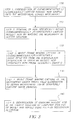
Fig. 3 is a workflow chart showing the process of how to use the
microarray system to analyze an unknown nucleic acid sample.
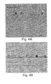
Figs. 4A, 4B, 4C and 4D show cross sections of a microarray
treated with gelatinase for different periods: 0 minutes -4B; 5 minutes -4C; and 7
minutes -4D.
Figs. 5A, 5B, and 5C show coated DNA microarrays captured
under a dark field without illumination after exposure to a solution containing
target nucleic acid sequence.
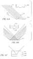
Figs. 6A, 6B, and 6C schematically show the optical design
principle respectively used to analyze coated color beads signals in absorption,
fluorescence and chemiluminescence detection systems.
As used herein, the term "sol-to-gel transition" or "gelation" means
a process by which fluid solutions or suspensions of particles form continuous
three-dimensional networks that exhibit no steady state flow. This can occur in
polymers by polymerization in the presence of polyfunctional monomers, by
covalent cross-linking of a dissolved polymer that possesses reactive side chains
and by secondary bonding, for example, hydrogen bonding, between polymer
molecules in solution. Polymers such as gelatin exhibit thermal gelation that is of
the latter type. The process of gelation or setting is characterized by a
discontinuous rise in velocity. (See, P.I. Rose, "Theory of the Photographic
Process", 4th Edition, T. H. James ed., pages 51-67).
As used herein, the term "random distribution" means a spatial
distribution of elements showing no reference or bias. Randomness can be
measured in terms of compliance with that which is expected by a Poisson
distribution.
As used herein, the term "enzyme" means a biological catalysts.
Similar to traditional chemical catalysts, enzymes speed the rate of biological
reactions by producing a transition state with a lower energy of activation than the
uncatalyzed reaction. In other words, enzymes are proteins specialized for the
reactions they catalyze. The preferred enzymes employed in this invention are
enzymes that catalytically hydrolyze the bonds of gelatin and may be referred to
as "gelatinases".
The present invention discloses a method for making an array of
micro-spheres, also referred to as "beads", on a substrate wherein the surface of
the micro-spheres bear capture agents, or probes, which are readily accessible to
analytes with which they come in contact. The distribution or pattern of the
micro-spheres on the substrate is entirely random and the micro-spheres are not
attracted or held to sites that are pre-marked or predetermined on the substrate as
in other methods previously disclosed. In the present invention, the micro-spheres
are immobilized randomly when the gelling agent in which they are carried
undergoes a sol-to-gel transition (also called "gelation").
As used herein, the term "gelling agent" means a substance that can
undergo gelation as described above. Examples include materials such as gelatin,
water-soluble cellulose ethers or poly (n-isopropylacrylamide) that undergo
thermal gelation or substances such as poly (vinyl alcohol) that may be chemically
cross-linked by a borate compound. A preferred gelling agent is alkali pretreated
gelatin. Other gelling agents may by polymers that may be cross-linked by
radiation such as ultraviolet radiation. Further examples of gelling agents include
acacia, alginic acid, bentonite, carbomer, carboxymethylcellulose sodium,
cetostearyl alcohol, colloidal silicon dioxide, ethylcellulose, gelatin, guar gum,
hydroxyethylcellulose, hydroxypropyl cellulose, hydroxypropyl methylcellulose,
magnesium aluminum silicate, maltodextrin, methylcellulose, polyvinyl alcohol,
povidone, propylene glycol alginate, sodium alginate, sodium starch glycolate,
starch, tragacanth and xanthum gum. (For further discussion on gelling agents,
see accompanying reference Secundrum Artem, Vol. 4, No. 5, Lloyd V. Allen).
Alpha or beta amylase or cellulase may be used to remove excess polysaccharides
and agarase may be used to remove excess agar.
The invention discloses a polymeric latex bead based random
microarray with each bead in the array having a distinct signature that would
distinguish the bead. Such a signature may be based on color, shape or size of the
bead. For signatures based on color, the color may be derived from mixing three
dyes representing the primary colors R, G, B to create thousands of
distinguishable beads with distinct "color addresses" (unique RGB values, e.g.
R=0, G=204, B=153). The beads can be made with sites on their surfaces that are
"active", meaning that at such sites physical or chemical interaction can occur
readily between the bead and other molecules or compounds. Such compounds
may be organic or inorganic. Usually, the molecule or compound is organic-nucleic
acid and fragments thereof, are examples. As in the examples below, to
the surface of each color coded bead may be attached a pre-synthesized
oligonucleotide, or other biological agents. Therefore, each color address can
correspond to a specific bioactive probe. These beads may be mixed in equal
amounts, and the random microarray fabricated by coating the mixed beads in a
single or multilayer format. Coating methods are broadly described by Edward
Cohen and Edgar B. Gutoff in Chapter 1 of "Modern Coating And Drying
Technology", (Interfacial Engineering Series; v.1), (1992), VCH Publishers Inc.,
New York, NY. For a single layer format, suitable coating methods may include
dip coating, rod coating, knife coating, blade coating, air knife coating, gravure
coating, forward and reverse roll coating, and slot and extrusion coating.
Coating methods are broadly described by Edward Cohen and
Edgar B. Gutoff in Chapter 1 of "Modern Coating And Drying Technology",
(Interfacial Engineering Series; v. 1), (1992), VCH Publishers Inc., New York,
New York. For a single layer format, suitable coating methods may include dip
coating, rod coating, knife coating, blade coating, air knife coating, gravure
coating, forward and reverse roll coating, and slot and extrusion coating.
Drying methods also vary, sometimes with surprisingly varying
results. Fill in your chill set and ambient drying. While the coating process
described in Example 1 with low temperature chill-set in combination with high
temperature drying does provide advantage of rapid manufacture, it also tends to
leave the surface of micro-spheres covered with a thin layer of gelling agent.
Such thin layer of gelling agent can interfere with the intended biological analysis
by preventing the access of analytes to the biological probes on the surface of
micro-spheres. It has been noted that if the coating was allowed to dry at ambient
temperature, e.g. room temperature, after the application of gelatin melt
containing micro-spheres, the upper surface of micro-spheres can be exposed
without any noticeable coverage of gelling agent. However, such ambient
temperature drying process takes much longer time to complete which
significantly slows down the manufacture process. The present invention
provides a method to resolve the problem of gel coverage over the surface of
micro-spheres and the method can be easily integrated into high speed coating
manufacture process.
A nucleic acid molecule is a linear polymer consisting of four
bases, A, T(U), G and C (T for DNA molecule and U for RNA molecule). The
interaction among four bases follows the "Watson-Crick" base pairing rule of A to
T(U) and G to C mediated by hydrogen bonds. When two single strand DNA
molecules having a perfect "Watson-Crick" base pairing match, they are referred
as a complementary strand. The interaction between two complementary strands
is termed hybridization. Sometimes complementary strands may contain one or
more base-pairing mismatches as well.
In order to use a nucleic acid microarray to analyze an unknown
nucleic acid sample, the nucleic acid sample to be analyzed has to be non-selectively
labeled by using fluorescent dyes or chemiluminescent active
molecules, followed by hybridizing the fluorescently/chemiluminescently labeled
biological nucleic acid sample can be hybridized to the bead based random to the
said color beads based random nucleic acid microarray. The method for labeling
nucleic acid sample has been well established and the protocols for the labeling
procedure can be found in many publications, for example, at
http://cmgm.stanford.edu/pbrown/protocols/index.html. The signals from both
"color addressable" polymeric beads and biological sample non-selectively
labeled nucleic acid fluorescence/chemiluminescence may be analyzed by a
charge coupled device after image enlargement through an optical system. The
recorded array image can be automatically analyzed by an image processing
algorithm to obtain bioactive probe information based on the RGB color code of
each bead, and the information compared to the fluorescence/chemiluminescence
image to detect and quantify specific biological analyte materials in the sample.
Optical or other electro-magnetic means may be applied to ascertain signature.
Although micro-spheres or particles having a substantially
curvilinear shape are preferred because of ease of preparation, particles of other
shape such as ellipsoidal or cubic particles may also be employed. Suitable
methods for preparing the particles are emulsion polymerization as described in
"Emulsion Polymerization" by I. Piirma, Academic Press, New York (1982) or by
limited coalescence as described by T. H. Whitesides and D. S. Ross in J. Colloid
Interface Science, vol. 169, pages 48-59, (1985). The particular polymer
employed to make the particles or micro-spheres is a water immiscible synthetic
polymer that may be colored. The preferred polymer is any amorphous water
immiscible polymer. Examples of polymer types that are useful are polystyrene,
poly(methyl methacrylate) or poly(butyl acrylate). Copolymers such as a
copolymer of styrene and butyl acrylate may also be used. Polystyrene polymers
are conveniently used. The formed micro-sphere is colored using an insoluble
colorant that is a pigment or dye that is not dissolved during coating or subsequent
treatment. Suitable dyes may be oil-soluble in nature. It is preferred that the dyes
are non-fluorescent when incorporated in the micro-spheres.
The micro-spheres are desirably formed to have a mean diameter in
the range of 1 to 50 microns; more preferably in the range of 3 to 30 microns and
most preferably in the range of 5 to 20 microns. It is preferred that the
concentration of micro-spheres in the coating is in the range of 100 to a million
per cm2, more preferably 1000 to 200,000 per cm2 and most preferably 10,000 to
100,000 per cm2.
The attachment of bioactive agents (often referred to as "probes")
to the surface of chemically functionalized micro-spheres can be performed
according to the published procedures in the art (Bangs Laboratories, Inc,
Technote #205). Some commonly used chemical functional groups include, but
not limited to, carboxyl, amino, hydroxyl, hydrazide, amide, chloromethyl, epoxy,
aldehyde, etc. Examples of bioactive agents or probes include, but are not limited
to, oligonucleotides, DNA and DNA fragments, PNAs, and synthetic molecules
capable of interacting specifically with a target such as a nucleic acid sequence.
The enzymes used in this invention include any enzyme, enzyme
preparation, or enzyme-containing formulation capable of dissolving or degrading
gelatin or other gelling agent used and substantially incapable of digesting or
inactivating the probe. By inactivating it is meant that the probe is inhibited from
reacting with a specific target under normal conditions of reaction. Thus,
"enzyme" in the context of this invention includes crude enzyme preparations,
such as crude plant or bacterial fermentation broth extracts, as well as purified
enzymes from plant, animal, or bacterial sources. Preparations of enzyme usable
in the process are understood to include activators, cofactors, and stabilizers that
are required for enzymatic activity, as well as stabilizers that enhance or preserve
enzyme activity.
Examples of suitable enzymes include serine proteases such as
Esperase™, Alcalase™, and Savinase™ (commercial enzyme preparations from
Novo Nordisk Corporation); Multifect P-3000™, HT Proteolytic 200™, Protex
6L™ and Protease 899™ (commercial enzyme preparations from Genencor
International Corporation); sulfhydryl proteases such as papain and bromelain;
and metaloproteases such as Neutrase™ (a commercial bacterial metaloenzyme
preparation from Novo Nordisk Corporation). The use of combinations of these
enzymes and enzyme types are also envisaged under this invention. Adducts of
enzymes with synthetic polymers are also envisaged in which enzyme molecules
are attached to synthetic polymers, which polymers may be larger or smaller than
the enzyme.
Other enzymes, preferably proteolytic, should also be suitable for
this application. The use of combinations of these enzymes and enzyme types are
also envisaged under this invention. Adducts of enzymes with synthetic polymers
are also envisaged in which enzyme molecules are attached to synthetic polymers,
which polymers may be larger or smaller than the enzyme.
Successful analytical imaging (resolution) of colored beads bearing
other fluorescent or luminescent reporters is a complicated but feasible task. The
preferred imaging system must be sufficiently flexible to execute all image
capture tasks without the movement of the prepared sample array. Based upon its
demonstrated merits, the full-frame capture of the array with a CCD camera is
preferred. Carefully designed array illumination is critical to both color and
fluorescent probe resolution. Considering the additional requirements imposed by
luminescent resolution, the minimum optical system requirements are satisfied
with a CCD sensor of at least 12-bits monochrome (<30 electrons read noise), 1
million pixels, 40% quantum efficiency, cooled (dark current <0.01 electron/sec),
utilizing an f/3 lens and a magnification of approximately one. A sensor pixel
approximately the size of a bead is most efficient; larger pixels compromise the
spatial resolution of beads and smaller pixels compromise the signal resolution
demanded for both color and reporter measurement. In theory, and in limited
practice, the above requirements enable the analysis of approximately 50,000
randomly dispersed beads per field of capture. Clearly, software analysis of vast
amounts of data must be implemented to manage the throughput of array images.
The software analysis must provide a measure of bead reporting, localize and
qualify a bead, calculate its color address, and possibly estimate its surface area in
a timely manner.
A carefully designed illumination system includes well-managed
epi-illumination (array illumination for the same side as the CCD camera). The
illumination must be conditioned/controlled monochromatic light, sufficiently
monochromatic to elicit appropriate color analysis and fluorescent excitation, and
sufficiently intense to assure reasonably short exposure times (minutes).
Illumination must be limited to an intensity that minimizes deleterious photolysis
or heat and that assures only single-photon fluorescent processes, simplifying the
effort to minimize undesirable fluorescent artifacts from solid supports and
various biological materials essential to the arrays. The full-frame image-capture
capability of the appropriately implemented CCD camera is uniquely qualified to
adhere to the requirements imposed by feasible illumination systems, but must be
assisted by precise optical filters to analyze light for the purpose of discerning
color and fluorescence. Appropriate interference filters are readily designed upon
specifying color dye and fluorescent reporter characteristics. Further, the
specified CCD camera can accommodate the capture and analysis of luminescent
reporters in about a 10 minute time period per field of capture. A tethered desktop
computer appropriately linked to hardware can feasibly implement all analyses
within a time period commensurate with the minutes required to gather all
relevant array data.
While the above hardware specifications may feasibly manage the
analysis of random bead arrays, the analysis is feasible only if the supporting
materials are optically qualified. Optical requirements of the array support
include appropriate cleanliness (artifact free, e.g., dust, debris, digs, scratches and
inclusions) and physical/optical requirements that minimize fluorescent
quenching, preclude fluorescent supports or colored dyes, and present a spatial
noise frequency and amplitude that minimally interfere with the array analysis. In
addition, the appropriate optical coupling of the array to the imaging system must
accommodate the requirements of both illumination and capture.
That the entire process is feasible may be assumed on the basis that
"common" photographic film is coated and processed to produce images that
resolve millions of colors at a spatial resolution of a few micrometers. By
comparison, the task of analyzing the random-bead microarray seems modest in
that only a thousand colors of about 10-micrometer resolution is required.
However, the bit-depth/sensitivity required, the essential delicate biochemistries
and the control of fluorescence present many challenges, and much of the
resolution common to photographic film will be sacrificed for the sake of meeting
the developmental challenges implicit in array analysis.
One of the feasible system set up for nucleic acid analysis based on
the description above was schematically shown in Figure 2 with the inventive
color beads based nucleic acid microarray and the necessary hardware
components. The design principle for such a system is described in detail in
Example 5. However, one skilled in the art can modified the system to produce
other variations similar to what is described in this invention. As shown coated
microarray A was placed on the surface of closed box H containing light source B
and light deflector D. The surface I contacting A can be made of transparent glass
or other plastic materials. E is an optical lens to focus a light signal from A onto
full frame electronic detector F (e.g., CCD, MOS), and the signal was analyzed by
computer G. In practice, the color beads barcode information can be captured by
illuminating the microarray with a conditioned/controlled monochromatic light B.
If the reporter signal from A is due to fluorescence, the fluorescence can be
excited using selected monochromatic light from B with cover C closed. If the
reporter signal from A is chemiluminescence, the microarray A will be in contact
with a chemiluminescence substrate solution and the reporter signal can be
captured in the dark with cover C closed.
Fig. 3 shows schematically a workflow chart on how to use the
described nucleic acid analysis system. In step 1, box 100
fluorescently/chemiluminescently labeled nucleic acid sample is hybridized to the
beads based random microarray. This step requires good physical contact of the
coated microarray with the nucleic acid sample by either placing a layer of sample
solution on the coated side of the microarray or dipping the microarray into the
sample solution. The non-specific bound nucleic acid will be removed in step 2
box 110 through multiple washing of the microarray in buffer solution. In step 3,
box 120, the fluorescence/chemiluminescence signals which resulted from the
hybridization of the unknown nucleic acid sample with probe sequences on the
surface of the coated micro-spheres are analyzed by an imaging system, as shown
in Fig. 2. The recorded fluorescence/chemiluminescence image designated as
IMAGE 1 stored in computer G. In step 4 box 130, a bright field illumination
condition is used to capture the color beads image to obtain the optical
signature/barcode information of the coated microarray. This image will be
designated as IMAGE2 and stored in computer H. In the final step, both IMAGE1
and IMAGE2 can be automatically analyzed using an image processing algorithm
to identify the unknown nucleic acid sequences by comparing IMAGE1 with
IMAGE2.
EXAMPLES
EXAMPLE 1
This example illustrates the preparation of colored micro-spheres
by incorporating dyes into the micro-spheres and the process of preparing the
coating containing colored micro-spheres.
Twenty four grams of a 4% aqueous suspension of polystyrene
beads prepared by emulsion polymerization and having a mean size of 9.5
micrometers was combined with 0.48 grams of poly(vinyl alcohol)(75%
hydrolyzed, molecular weight 2000).
A suspension of magenta colored beads was prepared by first
dissolving 0.084 grams of Dye 1 in 0.08 grams of toluene and 7.92 grams of
acetone. From the above suspension of polystyrene beads containing poly(vinyl
alcohol) an amount of 8.16 grams was then added slowly (drop-wise) to this
solution of the dyes while stirring to prepare a suspension of colored beads. The
suspension of colored beads was then filtered using a porous cotton filter, poured
into a dialysis bag (12,000 to 14,000 molecular weight cut off) and washed with
distilled water for one hour. After washing, the suspension of colored beads was
filtered again using a porous cotton filter. The concentration of magenta colored
beads in the suspension after this final step was 1.2%.
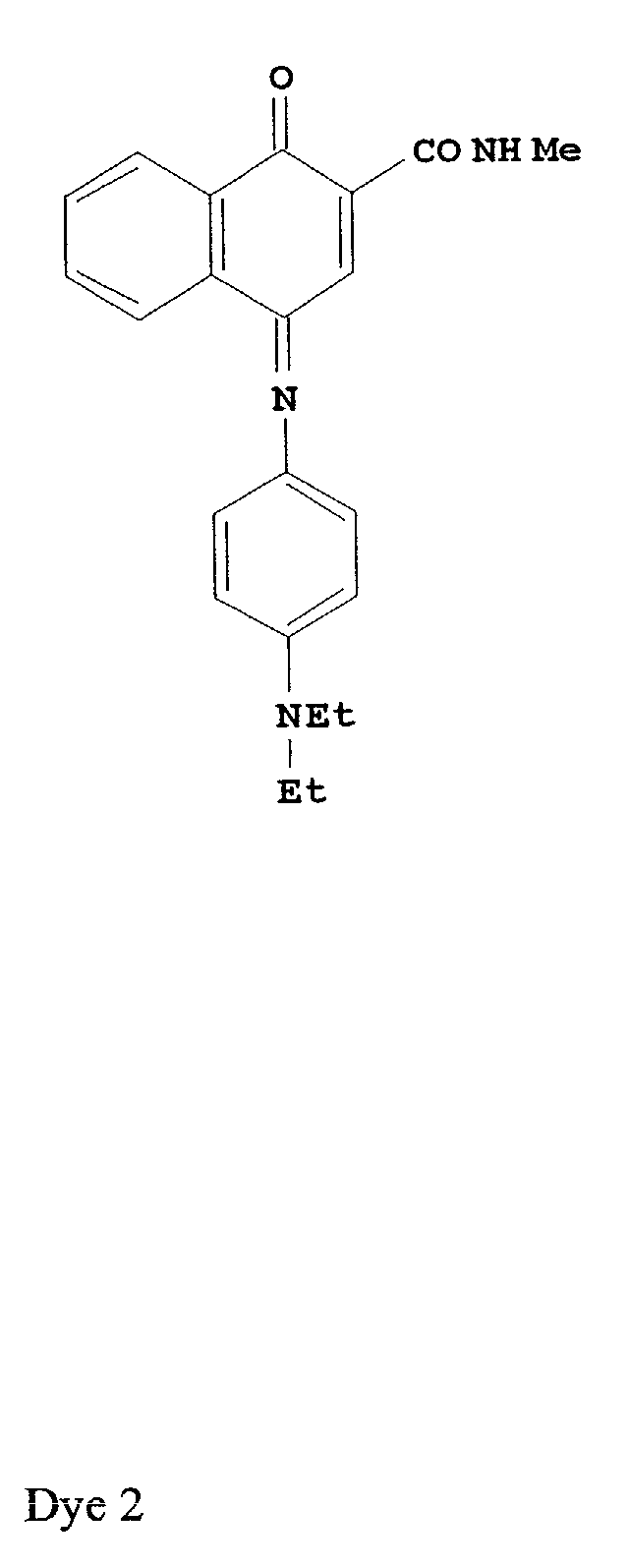
Suspensions of cyan and orange colored beads were prepared in a
similar manner using Dye 2 and Dye 3 (Sudan Orange 220 from BASF
corporation) respectively in place of Dye 1. The concentration of colored beads in
these suspensions were 1.6% and 1.45% respectively.
Formulations for coating were prepared in the following manner.
Formulation 1 (invention):
This was prepared by combining 4.0 grams of the suspension of
cyan colored beads, 5.33 grams of the magenta colored beads and 4.41 grams of
the orange colored beads with 13.91 grams of a 11.5% solution of lime processed
ossein gelatin in water, 3.2 grams of coating aid (6.8% solution of Triton X 200E
in water) and 49.15 grams of distilled water.
Formulation 2 (control):
A second formulation for coating was prepared by combining the
same amounts cyan, magenta and orange colored beads with 7.27 grams of
poly(vinyl alcohol) (GH23 from Nippon Gohsei) and 55.79 grams of water. The
amount of coating aid was the same as in formulation 1. The amount of
poly(vinyl alcohol) was chosen to match the viscosity of formulation 1 at the
higher temperatures (See, below).
Both samples (
formulation 1 and formulation 2) were equilibrated
in a 50°C water bath for 30 minutes and then analyzed using a Rheometric Fluid
Rheometer. Viscosities were determined as a function of temperature by the
dynamic oscillatory technique as the samples were cooled at the rate of one degree
centigrade per minute.
| Temperature (°C) | Viscosity (centipoise) |
| | Formulation 1 | Formulation 2 |
| 45 | 2.0 | 2.0 |
| 40 | 2.2 | 2.2 |
| 35 | 2.8 | 2.9 |
| 30 | 3.4 | 3.5 |
| 25 | 5.1 | 4.3 |
| 20 | 2107 | 4.6 |
| 15 | 100,000 | 6.0 |
| 10 | 440,000 | 7.9 |
It may be seen from the above data that at the higher temperatures
(above about 30°C), both samples behave similarly in terms of the increase in
viscosity upon cooling. However, below about 25°C formulation 1 (invention)
displays a much more dramatic increase in viscosity because of gelation. Such
behavior is not exhibited by formulation 2 (control). The viscosity of
formulation
1 increases by several orders of magnitude as the temperature is reduced from
25°C to 10°C. The temperature of onset of gelation is estimated to be 21.8°C.
A suspension of Cyan colored beads was prepared by first
dissolving 0.001 grams of dye 2 in 0.05 grams toluene and 4.95 grams
acetone. 2.5 grams of a 4% aqueous suspension of polystyrene beads
prepared by emulsion polymerization and having a mean size of 9.5
micrometers was then added slowly (drop-wise) to this solution of the dyes
while stirring to prepare a suspension of 1% dye loaded cyan dye. The
suspension of colored beads was then filtered using a porous cotton filter,
poured into a dialysis bag (12,000 to 14,000 molecular weight cut off) and
washed with distilled water for one hour. The concentration of cyan beads
in the suspension after this final step was 0.78%.
Suspensions of the other 5 levels of cyan dye incorporated
into the beads were prepared in a similar manner using 0.002 grams dye 2,
0.006 grams dye 2, 0.007 grams dye 2, 0.009 grams dye 2, and 0.01 grams
dye 2.
For preparing the last two samples, 2.5 grams of a 4%
aqueous suspension of polystyrene beads prepared by emulsion
polymerization and having a mean size of 9.5 micrometers was combined
with 0.48 grams of poly(vinyl alcohol)(75% hydrolyzed, molecular weight
2000). This was used in place of the polystyrene beads alone.
A 4% aqueous suspension of 2.5 grams polystyrene beads
prepared by emulsion polymerization and having a mean size of 9.5
micrometers was combined with 0.48 grams of poly(vinyl alcohol)(75%
hydrolyzed, molecular weight 2000).
A suspension of Magenta colored beads was prepared by
first dissolving 0.01 grams of dye 1 in 0.05 grams of toluene and 4.95
grams acetone. From the above suspension of polystyrene beads
containing poly(vinyl alcohol) an amount of 5.00 grams was then added
slowly (drop-wise) to this solution of the dyes while stirring to prepare a
suspension of 5% dye loaded Magenta dye. The suspension of colored
beads was then filtered using a porous cotton filter, poured into a dialysis
bag (12,000 to 14,000 molecular weight cut off) and washed with distilled
water for one hour. The concentration of cyan beads in the suspension
after this final step was 2.59%.
Suspensions of the other 4 colors of dye incorporated into
the beads were prepared in a similar manner using 0.05 grams of each of
the following dyes: dye 2(114FN-D89), dye 3 (BASF Sudan Orange 220),
dye 4 (MM2500FAN), and dye 5 (BASF Yellow 075). Plain polystyrene
beads were also used at 4% for the color white.
Formulation 1 and formulation 2 from Example 1 were
coated on a 0. 18 mm thick substrate of polyethyleneterephthalate (PET)
containing 6% by weight titanium dioxide using the coating device shown
in Figure 1. The formulations were introduced through a slot coating die
2, driven by a motor M 4, at a temperature of 45°C, on to a 12.7 cm wide
web 6 moving at the rate of 3.7 m/min. The flow rate was adjusted to
provide a level of 0.043 g/m2 for each of the cyan, magenta and orange
colored beads. The coatings were chill-set in a 2.4m long chilling section
8 that was maintained at a temperature of 4°C and 56.6% RH and then
passed through a conditioning chamber 10 before being dried in a first 12
and then a second 14 drying section that were 9.8m and 11.6m in length
respectively. The first drying section 12 was maintained at a temperature
of 21°C and 33.2% RH and the second 14 was maintained at a temperature
of 37.8°C and 18.6% RH.
EXAMPLE 2
This example illustrates the attachment of pre-synthesized single
strand oligonucleotide probe to the surface of dye incorporated beads.
Three DNA oligonucleotide probe sequences and their
complementary target sequences were used in this example as shown in Table 1.
The probe sequence was modified with primary amine at their 5 prime end and the
target sequence was modified with biotin at their 5 prime end.
One hundred microliters of Dye incorporated beads (4% w/v) was
rinsed three times in acetate buffer (0.01 M, pH5.0), and combined with one
hundred microliters of 20 mM 2-(4-Dimethylcarbomoyl-pyridino)-ethane-1-sulfonate
and ten percent of polyethyleneimine. The mixture was agitated at room
temperature for one hour and rinsed three times with sodium boric buffer (0.05 M,
pH8.3). The beads were re-suspended in sodium boric buffer.
An oligonucleotide DNA probe with 5'-amino-C6 modification
was dissolved in one hundred microliters of sodium boric buffer to a final
concentration of 40 nmol. A 20 microliters of cyanuric chloride in acetonitrile
was added to the DNA probe solution and the total volume was brought up to 250
microliter using sodium boric buffer. The solution was agitated at room
temperature for one hour and then dialyzed against one liter of boric buffer at
room temperature for three hours.
A 100 microliters of the dialyzed DNA solution was mixed with
200 microliters of beads suspension. The mixture was agitated at room
temperature for one hour and rinsed three times with sodium phosphate buffer
(0.01 M, pH7.0). The modified beads were coated onto transparent plastic support
according to formulation 1 as described in Example 1.
EXAMPLE 3
This example illustrates the hybridization and detection of target
nucleic acid sequences to the gelatin coated micro-sphere based microarray.
An oligonucleotide DNA with 5'-biotin labeling, which has
complementary sequence to the DNA probe, was dissolved in a hybridization
solution containing 0.9 M NaCI, 0.06 M NaH2PO4, 0.006 M EDTA, and 0.1%
SDS, pH 7.6 (6XSSPE-SDS) to a final concentration of 1µM. The bead coated
microarray was hybridized in the hybridization solution starting at 68°C and
slowly cooled down to room temperature. Following hybridization, the
microarray was washed in 0.5XSSPE-SDS for 15 minutes three times. The
microarray was incubated in a solution containing streptavidin-horseradish
peroxidase conjugate in a 0.01 M phosphate buffer 0.1 M NaCl pH7.0 for 1 hour
at room temperature. Following the incubation, the microarray was rinsed three
times with the incubation buffer.
The hybridization completed microarray was imaged with white
light illumination using Olympus BH-2 microscope (Diagnostic Instruments, Inc.
SPOT camera, CCD resolution of 1315 x 1033 pixels) to obtain the color beads
barcode signature information, followed by a dark field chemiluminescence image
capture by placing a thin layer of SuperSignal® ELISA chemiluminescence
substrate solution (purchased from PIERCE ENDOGEN) over the microarray.
EXAMPLE 4
This example illustrates the influence of the enzyme digestion on
DNA hybridization onto coatings containing colored micro-spheres or beads.
Gelatinase was purchased from Genencor International Inc. and
was used without further purification. Galatinase of 0.5 g was dissolved in 60 mL
of water. Coating containing colored micro-spheres was immersed in the enzyme
solution for various length of time at 37°C and the enzymolysis reaction was
stopped by dipping the enzyme treated coating into a running water bath for 5
minutes. The coatings treated with gelatinase for 0, 3, 5, and 7 minutes were cross
sectioned and the cross sections were imaged under microscope to visualize the
extent of gelatin removal. Fig. 4A shows treatment after 0 minutes; Fig. 4B
shows treatment after 3 minutes; Fig. 4C shows treatment after 5 minutes; and
Fig. 4D shows treatment after 7 minutes. It will be observed that as the time for
treatment increases, a larger surface of the bead is exposed.. The biotin labeled
target DNA fragment complimentary to the probe DNA sequence on the surface
of the beads were hybridized to the coating treated with gelatinase for various
length of time. The chemiluminescence signal was detected as described in
Example 3 and the results were summarized in Table 2
| Time of Gelatinase treatment | 0 minutes | 3 minutes | 5 minutes | 7 minutes |
| Chemiluminescence detection | No | Yes | Yes | Yes |
The chemiluminescence images for 3, 5 and 7 minutes enzyme treatment are
shown respectively in Figs. 5A, 5B, and 5C. It is important that the detected
micro-sphere signal improves as more micro-sphere surface is exposed.
This example illustrates only one condition for the enzymolysis
reaction. However, the condition for the enzymolysis reaction can also be
performed by dissolving the enzyme in buffered solutions or organic solvents and
carried out at appropriate temperature. One skilled in the arts can modify the
process to accommodate certain desirable applications.
Any method of enzymolysis is within the scope of the present
invention provided the gelling agent is substantially removed from the surface of
the micro-sphere which means that the probe attached to the surface is sufficiently
free of gelatin to interact with the intended target.
EXAMPLE 5
This example illustrates the preferred design principle to image and
analyze coated color beads on a flat surface.
The most accommodating approach to obtain image data from a
reporting flat object is full-frame image capture. The most important physical
aspects of the image capture system is the balance between efficient light
collection, optical resolution and effective illumination of the object and the
balanced system must accommodate luminescent, fluorescent and absorbance
modes of optical reporting. Further, the system must do so without significant
movement of the object of interest and the imaging data must support the
necessary measures relating to subsequent analysis. The design solutions to many
of these requirements are well known to practitioners of the art; however, the
system design to accommodate all requirements into a single practical solution
requires invention.
A rational approach to design is to adhere to the most important
dictates of the modes of imaging/detection: luminescent, fluorescent and
absorbance. The design principles are illustrated in Figs. 6A, 6B and 6C.
Fig. 6A shows a lens 210 and object plane 212. Fig. 6B shows lens
210, object plane 212, and filter 214. Fig. 6C shows optical platen 216, aqueous
layer 218, and object 220 on a mirror support.
The chief requirement of luminescent imaging/detection is efficient
light detection, influenced by both collection and photometric integration.
Efficient light collection requires a lens of large numerical aperture whose
diameter is approximately the size of the field of view and positioned at a working
distance that is close to the object. Practical solutions and cost lead to the solution
illustrated in Fig. 6A, wherein an optical system specification of a lens 210
approximately f2 (lens diameter about half the working distance between lens 210
and object plane 212) is represented. Photometric integration requires a well-implemented
sensor having sufficient dynamic range to generate a signal/noise
ratio appropriate to support analysis. In practice, an integrated, cooled CCD
sensor of 12-bits resolution and a quantum efficiency of >40% that produces a
signal/noise ratio >3000 suffices for contemporary chemiluminescent image
capture and readily enables photometric analysis with a linear dynamic range of
measure. An important practical limitation imposed by a lens with high numerical
aperture is a small depth of focus that requires controlled flatness of the object
plane. The plane of the object is consequently restricted in this system design by
an optical platen (see Fig. 6C). Further, the reporting surface of the object is
necessarily wet which offers the opportunity to optically couple the sample to the
optical platen. Optically coupling the object to the system is essential to the
intrascenic dynamic range of the measure (minimizing haze and other optical
artifacts that detract from measuring bright and dim features within the same field
of view).
The chief requirements of fluorescent imaging/detection are both
efficient light detection and appropriate management of illumination. The design
of efficient light detection discussed above (including optical coupling) delivers
all of the essential capability to fluorescent imaging. Illumination management
requires that excitation and emission light be discriminated. Design
considerations for conditioning the wavelength of excitation light is discussed
below (addressing absorption). Implicit to appropriate illumination management
is the elimination of stray light, particularly that which emanates from materials
that may fluoresce. Central to the design solution of this system is the
minimization of excitation light from the productive path of emitted light (the
acceptance cone of the lens system), as shown in Fig. 6A. This method of
exciting fluorescence is traditionally recognized by those familiar with the art to
be most effective; the method is generally called epi-illumination. Ideal epi-illumination
of a flat surface (object plane) would involve illumination with
parallel light at a 45° angle of incidence (shown as "I" in Fig. 6A). In practice, an
angle of incidence substantially less than 45° increases the possibility that
excitation light from a normal reflection will enter the acceptance cone of the lens;
sources of normal reflection include stray light from illumination and features in
the field of view that deviate from the object plane. An example of a design using
a small angle of incidence is that which uses "ring-light" illumination. Another
constraint is that the angle of incidence must be less than about 60°, else an
increasing amount of excitation light will not interact with the sample due to the
total reflection caused by the critical angle of the platen (Fig. 6C). Any practical
system of illumination will include light that is not parallel. It is practical, indeed
usual, to illuminate with light that is divergent as illustrated in Fig. 6B, where the
illumination is shown as the finer lines entering from both sides of the object, a
common method of epi-illumination used to enhance illumination uniformity.
The illustration depicts slightly divergent light (about 18 degrees, or
approximately f11), much less divergent than many commonly used methods such
fiber illumination. The epi-illumination shown in Fig. 6B is preferred, since the
extreme angles of incidence (and reflectance shown as bold lines) minimize the
possibility of stray light entering the acceptance cone of the lens or critically
reflecting from a planar surface.
A further important system design solution is embodied in Fig. 6C.
The platen composition is a controlled optical surface, and as such may be
constructed to minimize haze, autofluorescence and reflectance. Note that in this
system design, the platen is the only material with which the excitation light has
the opportunity to interact. Preferred composition of the platen is optical acrylic
(UV transparent), whose sensor/illumination side is coated with an anti-reflective
layer, and whose sample/object side is coated with an anti-abrasion layer (hardcoat).
Other compositions (such as fused silica) are acceptable, but will manifest
some performance decrement (transmit less light). As described above, the
aqueous layer (ubiquitous to biological/biochemical systems) optically couples the
sample surface to the platen and the object (the bead monolayer) is coated onto a
flexible support having a mirror surface. The vast majority of the excitation light,
which does not interact with the object beads, is simply reflected out of the
system, away from the lens.
To summarize, in this preferred epi-illumination system for
fluorescent excitation, the excitation light interacts only with a controlled optical
component, a thin aqueous solution and a target bead before the light has a
significant probability of entering the acceptance cone of the lens. Consequently,
the lens system need only discriminate excitation from emitted light that emanates
from the target bead. The discrimination of excitation from emitted light is
commonly practiced in fluorescent imaging/detection, commonly using an
interference filter (see filter 214-Fig. 6B). Such filters can be very costly and the
capability of the filter to efficiently discriminate excitation and emitted light is
often the chief limitation of detection sensitivity. In this preferred system design,
the requirement of the filter to discriminate is reduced approximately 1000-fold
compared to many fluorescent detection systems.
The chief requirements of absorption imaging/detection (generally
called colorimetry) involve spectral resolution and photometry. The photometric
precision of the system described above is more than 10-fold better than the basic
system requirements for resolving thousands of "colors". The application
requirement is similar to resolving/deconvoluting R, G, B and combinations/levels
thereof. The fundamental method of color resolution involves measurement of the
relative absorption characteristics of an object with differing wavelengths of light;
the relative differences are tabulated to functionally define categories of dye
combinations and levels. The dyes chosen must not interfere with other reporting
optical elements, such as fluorochromes. One way to minimize anticipated
interference is to choose "color" dyes whose absorbance spectrum is higher than
any excitation/emission spectrum of the reporting fluorochromes.
Given a sufficient photometric precision, the number of colors that
may be resolved (functionally defined) will depend upon the management of
illumination and detection of light. Two fundamentally different methods of light
management for the purpose of color resolution are either spectrally resolving
"white" light before or after the light interacts with an object. The above system
design requires that both methods be invoked for the sake of fluorescent imaging.
The preferred design solution that is suitable for both absorption and fluorescent
modes of imaging detection is to manage the spectral resolution of the
illumination. Therefore, the illumination is managed by a light source and
monochrometer, having sufficient power and resolution to accommodate both
modes of imaging. The solution is cost effective because the multi-filter design
and implementation that would accommodate the excitation of multiple
fluorescent probes and absorption of multiple colored dyes would easily exceed
the cost of monochromator. Since the spectral excitation/absorption of the organic
fluorochromes and dyes are relatively broad, a spectral resolution of only about 20
nm will suffice and the delivered illumination energy will be correspondingly
higher than that associated with a "high resolution" monochromater (typically < 2
nm). That the delivered energy will suffice for fluorescent imaging is assured by
the sensitivity of the camera which is designed for luminescent imaging.