EP1344711A2 - Rotational angle detecting apparatus, torque detecting apparatus and steering apparatus - Google Patents
Rotational angle detecting apparatus, torque detecting apparatus and steering apparatus Download PDFInfo
- Publication number
- EP1344711A2 EP1344711A2 EP03005521A EP03005521A EP1344711A2 EP 1344711 A2 EP1344711 A2 EP 1344711A2 EP 03005521 A EP03005521 A EP 03005521A EP 03005521 A EP03005521 A EP 03005521A EP 1344711 A2 EP1344711 A2 EP 1344711A2
- Authority
- EP
- European Patent Office
- Prior art keywords
- targets
- detecting means
- shaft
- rotational angle
- detecting
- Prior art date
- Legal status (The legal status is an assumption and is not a legal conclusion. Google has not performed a legal analysis and makes no representation as to the accuracy of the status listed.)
- Granted
Links
- 238000001514 detection method Methods 0.000 claims abstract description 116
- 238000006073 displacement reaction Methods 0.000 description 8
- 230000000630 rising effect Effects 0.000 description 5
- 239000000696 magnetic material Substances 0.000 description 4
- 238000003745 diagnosis Methods 0.000 description 1
- 230000000694 effects Effects 0.000 description 1
- 230000007935 neutral effect Effects 0.000 description 1
- 238000003672 processing method Methods 0.000 description 1
- 230000007306 turnover Effects 0.000 description 1
Images


Classifications
-
- G—PHYSICS
- G01—MEASURING; TESTING
- G01B—MEASURING LENGTH, THICKNESS OR SIMILAR LINEAR DIMENSIONS; MEASURING ANGLES; MEASURING AREAS; MEASURING IRREGULARITIES OF SURFACES OR CONTOURS
- G01B7/00—Measuring arrangements characterised by the use of electric or magnetic techniques
- G01B7/30—Measuring arrangements characterised by the use of electric or magnetic techniques for measuring angles or tapers; for testing the alignment of axes
-
- G—PHYSICS
- G01—MEASURING; TESTING
- G01D—MEASURING NOT SPECIALLY ADAPTED FOR A SPECIFIC VARIABLE; ARRANGEMENTS FOR MEASURING TWO OR MORE VARIABLES NOT COVERED IN A SINGLE OTHER SUBCLASS; TARIFF METERING APPARATUS; MEASURING OR TESTING NOT OTHERWISE PROVIDED FOR
- G01D5/00—Mechanical means for transferring the output of a sensing member; Means for converting the output of a sensing member to another variable where the form or nature of the sensing member does not constrain the means for converting; Transducers not specially adapted for a specific variable
- G01D5/12—Mechanical means for transferring the output of a sensing member; Means for converting the output of a sensing member to another variable where the form or nature of the sensing member does not constrain the means for converting; Transducers not specially adapted for a specific variable using electric or magnetic means
- G01D5/244—Mechanical means for transferring the output of a sensing member; Means for converting the output of a sensing member to another variable where the form or nature of the sensing member does not constrain the means for converting; Transducers not specially adapted for a specific variable using electric or magnetic means influencing characteristics of pulses or pulse trains; generating pulses or pulse trains
- G01D5/245—Mechanical means for transferring the output of a sensing member; Means for converting the output of a sensing member to another variable where the form or nature of the sensing member does not constrain the means for converting; Transducers not specially adapted for a specific variable using electric or magnetic means influencing characteristics of pulses or pulse trains; generating pulses or pulse trains using a variable number of pulses in a train
- G01D5/2454—Encoders incorporating incremental and absolute signals
- G01D5/2455—Encoders incorporating incremental and absolute signals with incremental and absolute tracks on the same encoder
- G01D5/2457—Incremental encoders having reference marks
-
- B—PERFORMING OPERATIONS; TRANSPORTING
- B62—LAND VEHICLES FOR TRAVELLING OTHERWISE THAN ON RAILS
- B62D—MOTOR VEHICLES; TRAILERS
- B62D15/00—Steering not otherwise provided for
- B62D15/02—Steering position indicators ; Steering position determination; Steering aids
-
- G—PHYSICS
- G01—MEASURING; TESTING
- G01D—MEASURING NOT SPECIALLY ADAPTED FOR A SPECIFIC VARIABLE; ARRANGEMENTS FOR MEASURING TWO OR MORE VARIABLES NOT COVERED IN A SINGLE OTHER SUBCLASS; TARIFF METERING APPARATUS; MEASURING OR TESTING NOT OTHERWISE PROVIDED FOR
- G01D5/00—Mechanical means for transferring the output of a sensing member; Means for converting the output of a sensing member to another variable where the form or nature of the sensing member does not constrain the means for converting; Transducers not specially adapted for a specific variable
- G01D5/12—Mechanical means for transferring the output of a sensing member; Means for converting the output of a sensing member to another variable where the form or nature of the sensing member does not constrain the means for converting; Transducers not specially adapted for a specific variable using electric or magnetic means
- G01D5/244—Mechanical means for transferring the output of a sensing member; Means for converting the output of a sensing member to another variable where the form or nature of the sensing member does not constrain the means for converting; Transducers not specially adapted for a specific variable using electric or magnetic means influencing characteristics of pulses or pulse trains; generating pulses or pulse trains
- G01D5/245—Mechanical means for transferring the output of a sensing member; Means for converting the output of a sensing member to another variable where the form or nature of the sensing member does not constrain the means for converting; Transducers not specially adapted for a specific variable using electric or magnetic means influencing characteristics of pulses or pulse trains; generating pulses or pulse trains using a variable number of pulses in a train
- G01D5/2451—Incremental encoders
- G01D5/2452—Incremental encoders incorporating two or more tracks having an (n, n+1, ...) relationship
-
- G—PHYSICS
- G01—MEASURING; TESTING
- G01L—MEASURING FORCE, STRESS, TORQUE, WORK, MECHANICAL POWER, MECHANICAL EFFICIENCY, OR FLUID PRESSURE
- G01L3/00—Measuring torque, work, mechanical power, or mechanical efficiency, in general
- G01L3/02—Rotary-transmission dynamometers
- G01L3/04—Rotary-transmission dynamometers wherein the torque-transmitting element comprises a torsionally-flexible shaft
- G01L3/10—Rotary-transmission dynamometers wherein the torque-transmitting element comprises a torsionally-flexible shaft involving electric or magnetic means for indicating
- G01L3/101—Rotary-transmission dynamometers wherein the torque-transmitting element comprises a torsionally-flexible shaft involving electric or magnetic means for indicating involving magnetic or electromagnetic means
- G01L3/104—Rotary-transmission dynamometers wherein the torque-transmitting element comprises a torsionally-flexible shaft involving electric or magnetic means for indicating involving magnetic or electromagnetic means involving permanent magnets
-
- G—PHYSICS
- G01—MEASURING; TESTING
- G01L—MEASURING FORCE, STRESS, TORQUE, WORK, MECHANICAL POWER, MECHANICAL EFFICIENCY, OR FLUID PRESSURE
- G01L5/00—Apparatus for, or methods of, measuring force, work, mechanical power, or torque, specially adapted for specific purposes
- G01L5/22—Apparatus for, or methods of, measuring force, work, mechanical power, or torque, specially adapted for specific purposes for measuring the force applied to control members, e.g. control members of vehicles, triggers
- G01L5/221—Apparatus for, or methods of, measuring force, work, mechanical power, or torque, specially adapted for specific purposes for measuring the force applied to control members, e.g. control members of vehicles, triggers to steering wheels, e.g. for power assisted steering
Definitions
- the present invention relates mainly to an automobile steering apparatus including a power steering apparatus using an electric motor and to a rotational angle detecting apparatus and a torque detecting apparatus therefor.
- the present invention relates to a rotational angle detecting apparatus wherein one or more targets are provided on a rotating member so that first detecting means outputs a detection signal as the rotating member rotates, second detecting means outputs a detection signal having a phase different from that of the detection signal of the first detecting means, and the rotational angle of the rotating member is detected on the basis of the detection signals outputted by the first detecting means and the second detecting means, to a torque detecting apparatus for detecting torque applied to a first shaft depending on a torsional angle generating in a connecting shaft for connecting the first shaft and a second shaft, and to a steering apparatus for generating a steering-assisting force on the basis of the detection result of the torque detecting apparatus.
- the so-called electric power steering apparatus wherein an electric motor is driven to assist steering in an automobile steering apparatus and to reduce a load on the driver is known.
- This apparatus comprises an input shaft connected to a steering wheel, an output shaft connected to wheels to be steered via a rack and pinion and a connecting shaft for connecting the input shaft to the output shaft.
- a torque detecting apparatus detects steering torque applied to the input shaft depending on a torsional angle generating in the connecting shaft, and a steering-assisting electric motor connected to the output shaft is driven and controlled on the basis of the steering torque detected by the torque detecting apparatus.
- a rotational angle detecting apparatus wherein one or more targets are provided on a rotating member so that first detecting means outputs a detection signal as the rotating member rotates, second detecting means outputs a detection signal having a phase different from that of the detection signal of the first detecting means, and the rotational angle of the rotating member is detected on the basis of the detection signals outputted by the first detecting means and the second detecting means; a torque detecting apparatus wherein the input shaft and the output shaft thereof are each provided with the rotational angle detecting apparatus, and torque applied to the input shaft is detected depending on a torsional angle generating in a connecting shaft for connecting the input shaft and the output shaft; and a steering apparatus for generating a steering-assisting force on the basis of the detection result of the torque detecting apparatus.
- the apparatus Since the above-mentioned rotational angle detecting apparatus cannot specify which target is detected by each of the detecting means, the apparatus detects only a relative rotational angle. The apparatus is sufficient to detect torque applied to the input shaft. However, the apparatus has a problem of being unable to detect an absolute rotational angle required to control the steering apparatus for generating a steering assisting force.
- the present invention is intended to provide a rotational angle detecting apparatus capable of detecting an absolute rotational angle, a torque detecting apparatus and a steering apparatus.
- a rotational angle detecting apparatus in accordance with a first aspect comprises: rotating member; one or more first targets provided on the rotating member; first detecting means, disposed opposite to the first targets, for outputting a detection signal as the rotating member rotates; and second detecting means for outputting a detection signal having a phase different from that of the detection signal of the first detecting means, whereby the rotational angle of the rotating member is detected on the basis of the detection signals outputted by the first detecting means and the second detecting means, comprising: second targets, the number of which is prime to the number of the first targets, provided on the rotating member or other rotating members rotating coaxially with the rotating member; third detecting means, disposed opposite to the second targets, for outputting a detection signal as the rotating member rotates; and fourth detecting means for outputting a detection signal having a phase different from that of the detection signal of the third detecting means; wherein the rotational angle of the rotating member is detected on the basis of the detection signals outputted by the first detecting means, the second detecting means, the third
- the first detecting means and the second detecting means output detection signals having phases different from each other by using the first targets.
- the third detecting means and the fourth detecting means output detection signals having phases different from each other by using the second targets.
- the rotational angle of the rotating member is detected on the basis of the detection signals outputted from the first detecting means, the second detecting means, the third detecting means and the fourth detecting means, respectively.
- the first detecting means, the second detecting means, the third detecting means and the fourth detecting means output sinusoidal detection signals respectively, whereby it is possible to realize a rotational angle detecting apparatus capable of detecting an absolute rotational angle.
- a rotational angle detecting apparatus in accordance with a second aspect is characterized in that the first targets and the second targets are formed of convex portions provided at nearly equal intervals in the circumferential directions of the rotating members.
- the first detecting means, the second detecting means, the third detecting means and the fourth detecting means output the sinusoidal detection signals periodically by using the first targets or the second targets, whereby it is possible to realize a rotational angle detecting apparatus capable of detecting an absolute rotational angle.
- a rotational angle detecting apparatus in accordance with a third aspect is characterized in that the first targets and the second targets are formed of non-concave portions provided between concave portions provided so that the non-concave portions are formed at nearly equal intervals in the circumferential directions of the rotating members.
- the first detecting means, the second detecting means, the third detecting means and the fourth detecting means output the sinusoidal detection signals periodically by using the first targets or the second targets, whereby it is possible to realize a rotational angle detecting apparatus capable of detecting an absolute rotational angle.
- a rotational angle detecting apparatus in accordance with a fourth aspect is characterized in that the first targets and the second targets are provided with magnetic poles magnetized so as to be reversed alternately in polarity at nearly equal intervals in the circumferential directions of the rotating members.
- the first detecting means, the second detecting means, the third detecting means and the fourth detecting means output the sinusoidal detection signals periodically by using the first targets or the second targets, whereby it is possible to realize a rotational angle detecting apparatus capable of detecting an absolute rotational angle.
- a torque detecting apparatus in accordance with a fifth aspect is characterized in that the rotational angle detecting apparatus as set forth in any one of first through fourth aspects is provided for a first shaft or a second shaft connected via a connecting shaft, the first targets, the first detecting means and the second detecting means are provided for the second shaft or the first shaft, and torque applied to the first shaft is detected on the basis of the difference between the detection signal outputted by the first detecting means or the second detecting means provided for the first shaft and the detection signal outputted by the first detecting means or the second detecting means provided for the second shaft depending on torsion generating in the connecting shaft.
- the torque applied to the first shaft is detected on the basis of the difference between the detection signal outputted by using the first targets by the first detecting means or the second detecting means provided on the second shaft and the detection signal outputted by using the first targets by the first detecting means or the second detecting means provided on the first shaft depending on the torsion generating in the connecting shaft. It is thus possible to realize a torque detecting apparatus provided with a rotational angle detecting apparatus capable of detecting an absolute rotational angle.
- a torque detecting apparatus in accordance with a sixth aspect is characterized in that the second targets provided in the rotational angle detecting apparatus are provided between the first targets provided on the first shaft and the first targets provided on the second shaft.
- the second targets are provided between the first targets.
- the arrangement positions of the first detecting means, the second detecting means, the third detecting means and the fourth detecting means can be determined so as to have one arrangement order, whereby the cost of producing the apparatus can be reduced.
- a steering apparatus in accordance with a seventh aspect comprises a first shaft connected to a steering member: a second shaft connected to a steering mechanism; a connecting shaft for connecting the first shaft and the second shaft; and the torque detecting apparatus, as set forth in fifth or sixth aspect, for detecting steering torque applied to the first shaft on the basis of a torsional angle generating in the connecting shaft; whereby steering assisting is carried out depending on the steering torque detected by the torque detecting apparatus.
- the torque detecting apparatus detects the steering torque applied to the first shaft on the basis of the torsional angle generating in the connecting shaft, and steering assisting is carried out depending on the detected steering torque, whereby it is possible to realize a steering apparatus provided with the torque detecting apparatus in accordance with the fifth or sixth aspect.
- FIG. 1 is a schematic view showing the configurations of a rotational angle detecting apparatus, a torque detecting apparatus and a steering apparatus in accordance with an embodiment of the present invention, mainly applied to automobiles, for example.
- an input shaft 16 (a rotating member functioning as a first shaft) whose upper end portion is connected to a steering wheel 1 (a steering member) is coaxially connected to an output shaft 17 (a rotating member functioning as a second shaft) whose lower end portion is connected to a pinion 18 in a steering mechanism (not shown) via a torsion bar 19 (a connecting shaft) having a small diameter, whereby a steering shaft 13 for connecting the steering wheel 1 to the steering mechanism is formed.
- the configuration in the vicinity of the connecting portion between the input shaft 16 and the output shaft 17 is described below.
- first targets which are convex portions made of a magnetic material, 36 pieces for example, are provided at equal intervals so as to protrude in the circumferential direction.
- a plurality of targets 3b which are convex portions made of a magnetic material, are provided at equal intervals so as to protrude in the circumferential direction.
- the number of the targets 3b is for example 37, a number being prime to the number of the targets 3a.
- the fact that two numbers are prime to each other means that they do not have any common divisors other than one.
- the targets 3a and 3b are formed of the teeth of spur gears having involute teeth, and the circular spur gears are used to form the target plates 12a and 12b and the targets 3a and 3b.
- a target plate 12c (a rotating member) provided with 36 targets 3c (first targets) similar to the above-mentioned targets 3a is also fitted on the output shaft 17 and secured thereto.
- the targets 3c of the target plate 12c on the side of the output shaft 17 and the targets 3a of the target plate 12a on the side of the input shaft 16 are aligned in the circumferential direction and provided in parallel.
- the teeth serving as the targets 3a, 3b and 3c may be formed by gear cutting the circumferential faces of the input shaft 16 and the output shaft 17 made of a magnetic material.
- a sensor box 11a is disposed so as to face the outer fringes of the targets 3a, 3b and 3c on the outer circumferential faces of the target plates, respectively.
- the sensor box 11a is secured to and supported by a stationary portion, such as a housing (not shown), for rotatably supporting the input shaft 16 and the output shaft 17.
- Magnetic sensors 1A and 1B (first detecting means and second detecting means) disposed at different positions opposite to each other in the circumferential direction of the targets 3a on the side of the input shaft 16 and the magnetic sensors 2A and 2B (first detecting means and second detecting means) disposed at different positions opposite to each other in the circumferential direction of the targets 3c on the side of the output shaft 17 are correctly aligned in the circumferential direction and contained inside the sensor box 11a.
- magnetic sensors 3A and 3B (third detecting means and fourth detecting means) disposed at different positions opposite to each other in the circumferential direction of the targets 3b on the side of the input shaft 16 are also contained therein.
- the magnetic sensors 1A, 1B, 2A, 2B, 3A and 3B are formed of a device having an electrical characteristic (resistance) changing depending on magnetic field action, such as a magnetoresistance effect device (an MR device), and configured so that their detection signals change depending on the portions of the targets 3a, 3c and 3b disposed close and opposite thereto.
- the detection signals of these magnetic sensors 1A, 1B, 2A, 2B, 3A and 3B are supplied to an operation circuit 10 comprises a microprocessor provided inside or outside the sensor box 11a.
- the operation circuit 10 includes a table 14 in which the rotational angle of the input shaft 16 at the time of its rotation and the previously measured detection signal values of the magnetic sensors 1A, 1B, 3A and 3B are stored so as to have correspondence therebetween.
- the magnetic sensors 1A, 1B, 2A, 2B, 3A and 3B output detection signals having waveforms similar to triangular or sinusoidal waveforms as the targets 3a, 3c and 3b pass by.
- the nonlinear change rate of each of the detection signals is maximized in the vicinity of a turning point from rising to lowering or from lowering to rising.
- interpolation can be carried out by using a signal processing method described below.
- the magnetic sensors 1A, 1B, 2A, 2B, 3A and 3B output detection signals rising and lowering depending on the change in the rotational angle of each of the input shaft 16 and the output shaft 17 as shown in FIG. 2A, FIG. 2B and FIG. 2C, respectively, while the targets 3a, 3c and 3b pass by the positions opposite to the corresponding sensors, respectively.
- the detection signals of the magnetic sensors 1A and 1B correspond to the rotational angle of the input shaft 16 provided with the targets 3a disposed opposite to these magnetic sensors.
- the detection signals of the magnetic sensors 3A and 3B correspond to the rotational angle of the input shaft 16 provided with the targets 3b disposed opposite to these magnetic sensors.
- the detection signals of the magnetic sensors 2A and 2B correspond to the rotational angle of the output shaft 17 provided with the targets 3c disposed opposite to these magnetic sensors.
- the operation circuit 10 can calculate the relative rotational angle of the input shaft 16 from the detection signals of the magnetic sensors 1A and 1B, whereby the operation circuit 10 and the magnetic sensors 1A and 1B operate as a rotational angle detecting apparatus for the input shaft 16.
- the operation circuit 10 can calculate the relative rotational angle of the output shaft 17 from the detection signals of the magnetic sensors 2A and 2B, whereby the operation circuit 10 and the magnetic sensors 2A and 2B operate as a rotational angle detecting apparatus for the output shaft 17.
- the magnetic sensors 1A and 2A are different in phase from the magnetic sensors 1B and 2B by an electrical angle of 90°, for example, in the circumferential directions of the target plates 12a and 12c, respectively.
- the nonlinear change rate of each of the detection signals is maximized at maximal and minimal values as turning points of rising and lowering. Because of the difference in phase, interpolation is possible with each other. In the case when interpolation is possible, the difference in phase may be any electrical angle of 1° to less than 360°.
- the difference between the detection signal of the magnetic sensor 1A and the detection signal of the magnetic sensor 2A or the difference between the detection signal of the magnetic sensor 1B and the detection signal of the magnetic sensor 2B corresponds to the difference (relative angle displacement) between the rotational angle of the input shaft 16 and the rotational angle of the output shaft 17.
- This relative angle displacement corresponds to a torsional angle generating in a torsion bar 19 connected between the input shaft 16 and the output shaft 17 when torque is applied to the input shaft 16.
- the torque applied to the input shaft 16 can be calculated on the basis of the difference between the above-mentioned detection signals.
- the magnetic sensors 3A and 3B are different in phase from each other by an electrical angle of 90° in the circumferential direction of the target plate 12b.
- the number of the targets 3a disposed opposite to the magnetic sensors 1A and 1B is 36
- the number of the targets 3b disposed opposite to the magnetic sensors 3A and 3B is 37.
- the rotational angle of the input shaft 16 can be specified by referring to the detection signal values of the magnetic sensors 1A, 3A, 1B and 3B stored in the table 14.
- the number of the targets disposed opposite to the magnetic sensors 3A and 3B serving as absolute angle (detection) sensors is different from the number of the targets disposed opposite to the magnetic sensors 1A and 1B serving as input (shaft) relative angle (detection) sensors and the number of the magnetic sensors 2A and 2B serving as output (shaft) relative angle (detection) sensors.
- the arrangement interval of the magnetic sensors 3A and 3B is different from that of the magnetic sensors 1A and 1B and that of the magnetic sensors 2A and 2B.
- the absolute rotational angle of the input shaft 16 or the absolute rotational angle of the output shaft 17 is detected depending on the type of vehicle to which the steering apparatus is applied.
- a target plate for absolute angle (detection), such as the target plate 12b, and a target plate for input (shaft) relative angle (detection), such as the target plate 12a, can be arranged on the input shaft 16 in this order from above, and a target plate for output (shaft) relative angle (detection), such as the target plate 12c, can be arranged on the output shaft 17, as shown in a schematic view of FIG. 4A.
- the target plate for input (shaft) relative angle (detection) can be arranged on the input shaft 16 and the target plate for output (shaft) relative angle (detection) and the target plate for absolute angle (detection) can be arranged on the output shaft 17 in this order from above, as shown in a schematic view of FIG. 4B.
- the arrangement positions of the absolute angle (detection) sensors in a sensor box such as the sensor box 11a, must be changed up and down in each of the above-mentioned arrangement cases. It is thus necessary to produce two kinds of sensor boxes.
- the target plate for input (shaft) relative angle (detection) and the target plate for absolute angle (detection) can be arranged on the input shaft 16 in this order from above, and the target plate for output (shaft) relative angle (detection) can be arranged on the output shaft 17, as shown in a schematic view of FIG. 4C.
- the target plate for input (shaft) relative angle (detection) can be arranged on the input shaft 16 and the target plate for absolute angle (detection) and the target plate for output (shaft) relative angle (detection) can be arranged on the output shaft 17 in this order from above.
- the above-mentioned targets are not particularly limited in configuration, provided that the detection signals of the magnetic sensors change as the target plates (rotating members) rotate.
- the target plates 12a, 12b and 12c can also have a configuration wherein convex portions are formed at nearly equal intervals in the circumferential directions thereof so that the distance between each of the magnetic sensors and the convex portions close thereto changes as the target plates 12a, 12b and 12c rotate.
- target plates 12a, 12b and 12c instead of the target plates 12a, 12b and 12c, it is also possible to use target plates 12e, 12f and 12g provided with concave portions 3eo, 3fo and 3go, respectively, so as to form non-concave portions 3e, 3f and 3g at nearly equal intervals in the circumferential directions of the outer circumferential surfaces of the target plate as shown in FIG. 5.
- the concave portions 3eo, 3fo and 3go are through holes.
- target plates 12a, 12b and 12c instead of the target plates 12a, 12b and 12c, it is also possible to use target plates 12h, 12i and 12j whose outer circumferential surfaces 3h, 3i and 3j are magnetized so as to be reversed alternately in polarity at nearly equal intervals in the circumferential directions thereof as shown in FIG. 6. Since the magnetic poles close to the magnetic sensors 1A, 1B, 3A, 3B, 2A and 2B are reversed alternately in polarity, positive/negative (NS), as the target plates 12h, 12i and 12j rotate, the intensity of the magnetic field detected depending on the change in the distance between each of the magnetic sensors 1A, 1B, 3A, 3B, 2A and 2B and the magnetic poles close thereto is changed.
- NS positive/negative
- FIG. 7 is a schematic view showing the configurations of a rotational angle detecting apparatus, a torque detecting apparatus and a steering apparatus in accordance with another embodiment.
- target plates 12c and 12d are fitted coaxially on the output shaft 17 of the torque detecting apparatus and the steering apparatus described in FIG. 1 and secured thereto with the target plate 12c disposed on the side of the steering wheel 1, whereby an output shaft 17a is formed.
- targets 3d which are convex portions made of a magnetic material, 37 pieces for example, protrude at equal intervals in the circumferential direction.
- the targets 3c of the target plate 12c on the side of the output shaft 17a and the targets 3a of the target plate 12a on the side of the input shaft 16 are aligned in the circumferential direction and provided in parallel.
- the number of the targets 3c (teeth) is different from the number of the targets 3d (teeth) by one.
- a sensor box 11b is disposed so as to face the outer fringes of the targets 3a, 3b, 3c and 3d formed on the outer circumferences of the target plates, respectively.
- the sensor box 11b is secured to and supported by a stationary portion, such as a housing, for rotatably supporting the input shaft 16 and the output shaft 17a.
- the magnetic sensors 4A and 4B are similar to the magnetic sensors 1A and 1B.
- the detection signals of the magnetic sensors 1A, 1B, 2A, 2B, 3A, 3B, 4A and 4B are supplied to an operation circuit 10a comprises a microprocessor provided inside or outside the sensor box 11b.
- the operation circuit 10a includes a table 14a (identical to the table 14 of FIG. 1) in which the rotational angle of the input shaft 16 at the time of its rotation and the measured detection signal values of the magnetic sensors 1A, 1B, 3A and 3B are stored so as to have correspondence therebetween.
- the operation circuit 10a also includes a table 14b in which the rotational angle of the output shaft 17a at the time of its rotation and the measured detection signals values of the magnetic sensors 2A, 2B, 4A and 4B are stored so as to have correspondence therebetween.
- the magnetic sensors 1A, 1B, 2A, 2B, 3A, 3B, 4A and 4B output detection signals having waveforms similar to triangular or sinusoidal waveforms as the targets 3a, 3c, 3b and 3d pass by.
- the other configurations of this steering apparatus are similar to those of the steering apparatus described in FIG. 1. Hence, the same elements are designated by the same reference numerals, and their explanations are omitted.
- the magnetic sensors 1A, 1B, 2A, 2B, 3A, 3B, 4A and 4B output detection signals rising and lowering depending on the change in the rotational angle of each of the input shaft 16 and the output shaft 17a as shown in FIG. 2A, while the targets 3a, 3c, 3b and 3d pass by the positions opposite to the corresponding sensors.
- the detection signals of the magnetic sensors 4A and 4B correspond to the rotational angle of the output shaft 17a provided with the targets 3d disposed opposite to these magnetic sensors.
- the magnetic sensors 4A and 4B are different in phase from each other by an electrical angle of 90° in the circumferential direction of the target plate 12d.
- the number of the targets 3c disposed opposite to the magnetic sensors 2A and 2B is 36
- the number of the targets 3d disposed opposite to the magnetic sensors 4A and 4B is 37.
- the rotational angle detecting apparatus In the case when only the magnetic sensors 2A and 4A or only the magnetic sensors 2B and 4B are used, one set of the same detection signal values generates twice while the input shaft 16 rotates 360° as shown in FIG. 3. Hence, the rotational angle (absolute rotational angle) of the input shaft 16 cannot be specified. However, the rotational angle of the input shaft 16 can be specified by referring to the detection signal values of the magnetic sensors 2A, 4A, 2B and 4B stored in the table 14b.
- the other operations of the rotational angle detecting apparatus, the torque detecting apparatus and the steering apparatus are similar to those of the rotational angle detecting apparatus, the torque detecting apparatus and the steering apparatus described in FIG. 1. Hence, the same elements are designated by the same reference numerals, and their explanations are omitted.
- the magnetic sensors 1A, 1B, 2A, 2B, 3A, 3B, 4A and 4B that is eight channels, are used as described above, and if one or both of the channels 1A and 1B become faulty, the faulty channels 1A and/or 1B are specified, and the torque can be detected by the channels 3A, 3B, 4A and 4B, and the rotational angle (absolute rotational angle) can be detected by the channels 2A, 2B, 4A and 4B normally and continuously at all times.
- the steering apparatus operates without problems, and the fault can be notified (a diagnosis signal is outputted), and the absolute rotational angle of the input shaft or the output shaft can be detected continuously.
- FIG. 8 is a schematic view showing the configurations of a torque detecting apparatus and a steering apparatus in accordance with still another embodiment.
- the target plate 12b is eliminated from the input shaft 16 of the rotational angle detecting apparatus, the torque detecting apparatus and the steering apparatus described in FIG. 1, whereby an input shaft 16a is formed.
- a sensor box 11 is disposed so as to face the outer fringes of the targets 3a and 3c on the outer circumferences of the target plates 12a and 12c, respectively.
- the sensor box 11 is secured to and supported by a stationary portion, such as a housing, for rotatably supporting the input shaft 16a and the output shaft 17.
- the magnetic sensors 1A and 1B disposed at different positions opposite to each other in the circumferential direction of the targets 3a on the side of the input shaft 16a and the magnetic sensors 2A and 2B disposed at different positions opposite to each other in the circumferential direction of the targets 3c on the side of the output shaft 17 are correctly aligned in the corresponding respective circumferential directions and contained inside the sensor box 11.
- the detection signals of the magnetic sensors 1A, 1B, 2A and 2B are supplied to an operation circuit 10b comprises a microprocessor provided inside or outside the sensor box 11.
- the operation circuit 10b is provided with a reference phase difference memory 15 for storing the displacement of the phase difference between the targets 3a and 3c at the time when the torsion of the torsion bar 19 measured during assembly is zero, a phase difference operation unit 20 for operating the phase difference between the targets 3a and 3c on the basis of the detection signals of the magnetic sensors 1A, 1B, 2A and 2B, and a phase difference compensation unit 21 for compensating for the phase difference between the targets 3a and 3c on the basis of the phase difference operated by the phase difference operation unit 20 and the displacement of the phase difference stored in the reference phase difference memory 15.
- the operation circuit 10b outputs a torque signal based on the phase difference compensated for by the phase difference compensation unit 21.
- the other configurations of the torque detecting apparatus and the steering apparatus are similar to those of the torque detecting apparatus and the steering apparatus described in to FIG. 1. Hence, the same elements are designated by the same reference numerals, and their explanations are omitted.
- the number of the teeth i.e., the targets 3a and 3c
- the left/right torsional angles (mechanical stopper angles) of the torsion bar 19 are ⁇ 4°, for example, no difference occurs between the left/right torque values as shown in FIG. 9A, provided that no error is present in the assembly of the target plates 12a and 12c and the input/output shafts 16a and 17.
- a torsional angle of +4.5° and a torsional angle of -4.5° are the same as phase difference signals. Furthermore, a torsional angle of -4° and a torsional angle of +5° are also the same as phase difference signals.
- the phase difference operation unit 20 performs an operation to obtain the phase difference between the targets 3a and 3c on the basis of the detection signals of the magnetic sensors 1A, 1B, 2A and 2B. Furthermore, the phase difference compensation unit 21 compensates for the phase difference obtained by the operation on the basis of the displacement of the phase difference stored in the reference phase difference memory 15 and outputs a torque signal based on the compensated phase difference.
- the first detecting means, the second detecting means, the third detecting means and the fourth detecting means output sinusoidal detection signals respectively, whereby it is possible to realize a rotational angle detecting apparatus capable of detecting an absolute rotational angle.
- rotational angle detecting apparatuses in accordance with the second and third aspects, it is possible to realize rotational angle detecting apparatuses capable of detecting an absolute rotational angle.
- the first detecting means, the second detecting means, the third detecting means and the fourth detecting means output the sinusoidal detection signals periodically, whereby it is possible to realize a rotational angle detecting apparatus capable of detecting an absolute rotational angle.
- torque detecting apparatus in accordance with the fifth aspect, it is possible to realize a torque detecting apparatus provided with a rotational angle detecting apparatus capable of detecting an absolute rotational angle.
- the arrangement positions of the first detecting means, the second detecting means, the third detecting means and the fourth detecting means can be determined so as to have one arrangement order, whereby the cost of producing the apparatus can be reduced.
Landscapes
- Physics & Mathematics (AREA)
- General Physics & Mathematics (AREA)
- Engineering & Computer Science (AREA)
- Electromagnetism (AREA)
- Chemical & Material Sciences (AREA)
- Combustion & Propulsion (AREA)
- Transportation (AREA)
- Mechanical Engineering (AREA)
- Power Steering Mechanism (AREA)
- Measurement Of Length, Angles, Or The Like Using Electric Or Magnetic Means (AREA)
- Length Measuring Devices With Unspecified Measuring Means (AREA)
- Transmission And Conversion Of Sensor Element Output (AREA)
Abstract
Description
- The present invention relates mainly to an automobile steering apparatus including a power steering apparatus using an electric motor and to a rotational angle detecting apparatus and a torque detecting apparatus therefor.
- More particularly, the present invention relates to a rotational angle detecting apparatus wherein one or more targets are provided on a rotating member so that first detecting means outputs a detection signal as the rotating member rotates, second detecting means outputs a detection signal having a phase different from that of the detection signal of the first detecting means, and the rotational angle of the rotating member is detected on the basis of the detection signals outputted by the first detecting means and the second detecting means, to a torque detecting apparatus for detecting torque applied to a first shaft depending on a torsional angle generating in a connecting shaft for connecting the first shaft and a second shaft, and to a steering apparatus for generating a steering-assisting force on the basis of the detection result of the torque detecting apparatus.
- The so-called electric power steering apparatus wherein an electric motor is driven to assist steering in an automobile steering apparatus and to reduce a load on the driver is known. This apparatus comprises an input shaft connected to a steering wheel, an output shaft connected to wheels to be steered via a rack and pinion and a connecting shaft for connecting the input shaft to the output shaft. In the apparatus, a torque detecting apparatus detects steering torque applied to the input shaft depending on a torsional angle generating in the connecting shaft, and a steering-assisting electric motor connected to the output shaft is driven and controlled on the basis of the steering torque detected by the torque detecting apparatus.
- The applicant of this application in Japan has proposed, in Japanese Patent Application No. 2001-292534, a rotational angle detecting apparatus wherein one or more targets are provided on a rotating member so that first detecting means outputs a detection signal as the rotating member rotates, second detecting means outputs a detection signal having a phase different from that of the detection signal of the first detecting means, and the rotational angle of the rotating member is detected on the basis of the detection signals outputted by the first detecting means and the second detecting means; a torque detecting apparatus wherein the input shaft and the output shaft thereof are each provided with the rotational angle detecting apparatus, and torque applied to the input shaft is detected depending on a torsional angle generating in a connecting shaft for connecting the input shaft and the output shaft; and a steering apparatus for generating a steering-assisting force on the basis of the detection result of the torque detecting apparatus.
- Since the above-mentioned rotational angle detecting apparatus cannot specify which target is detected by each of the detecting means, the apparatus detects only a relative rotational angle. The apparatus is sufficient to detect torque applied to the input shaft. However, the apparatus has a problem of being unable to detect an absolute rotational angle required to control the steering apparatus for generating a steering assisting force.
- Accordingly, the present invention is intended to provide a rotational angle detecting apparatus capable of detecting an absolute rotational angle, a torque detecting apparatus and a steering apparatus.
- A rotational angle detecting apparatus in accordance with a first aspect comprises: rotating member; one or more first targets provided on the rotating member; first detecting means, disposed opposite to the first targets, for outputting a detection signal as the rotating member rotates; and second detecting means for outputting a detection signal having a phase different from that of the detection signal of the first detecting means, whereby the rotational angle of the rotating member is detected on the basis of the detection signals outputted by the first detecting means and the second detecting means, comprising: second targets, the number of which is prime to the number of the first targets, provided on the rotating member or other rotating members rotating coaxially with the rotating member; third detecting means, disposed opposite to the second targets, for outputting a detection signal as the rotating member rotates; and fourth detecting means for outputting a detection signal having a phase different from that of the detection signal of the third detecting means; wherein the rotational angle of the rotating member is detected on the basis of the detection signals outputted by the first detecting means, the second detecting means, the third detecting means and the fourth detecting means.
- In this rotational angle detecting apparatus, as the rotating member rotates, the first detecting means and the second detecting means output detection signals having phases different from each other by using the first targets. As the rotating member rotates, the third detecting means and the fourth detecting means output detection signals having phases different from each other by using the second targets. The rotational angle of the rotating member is detected on the basis of the detection signals outputted from the first detecting means, the second detecting means, the third detecting means and the fourth detecting means, respectively.
- Hence, the first detecting means, the second detecting means, the third detecting means and the fourth detecting means output sinusoidal detection signals respectively, whereby it is possible to realize a rotational angle detecting apparatus capable of detecting an absolute rotational angle.
- A rotational angle detecting apparatus in accordance with a second aspect is characterized in that the first targets and the second targets are formed of convex portions provided at nearly equal intervals in the circumferential directions of the rotating members.
- In this rotational angle detecting apparatus, as the rotating member rotates, the first detecting means, the second detecting means, the third detecting means and the fourth detecting means output the sinusoidal detection signals periodically by using the first targets or the second targets, whereby it is possible to realize a rotational angle detecting apparatus capable of detecting an absolute rotational angle.
- A rotational angle detecting apparatus in accordance with a third aspect is characterized in that the first targets and the second targets are formed of non-concave portions provided between concave portions provided so that the non-concave portions are formed at nearly equal intervals in the circumferential directions of the rotating members.
- In this rotational angle detecting apparatus, as the rotating member rotates, the first detecting means, the second detecting means, the third detecting means and the fourth detecting means output the sinusoidal detection signals periodically by using the first targets or the second targets, whereby it is possible to realize a rotational angle detecting apparatus capable of detecting an absolute rotational angle.
- A rotational angle detecting apparatus in accordance with a fourth aspect is characterized in that the first targets and the second targets are provided with magnetic poles magnetized so as to be reversed alternately in polarity at nearly equal intervals in the circumferential directions of the rotating members.
- In this rotational angle detecting apparatus, as the rotating member rotates, the first detecting means, the second detecting means, the third detecting means and the fourth detecting means output the sinusoidal detection signals periodically by using the first targets or the second targets, whereby it is possible to realize a rotational angle detecting apparatus capable of detecting an absolute rotational angle.
- A torque detecting apparatus in accordance with a fifth aspect is characterized in that the rotational angle detecting apparatus as set forth in any one of first through fourth aspects is provided for a first shaft or a second shaft connected via a connecting shaft, the first targets, the first detecting means and the second detecting means are provided for the second shaft or the first shaft, and torque applied to the first shaft is detected on the basis of the difference between the detection signal outputted by the first detecting means or the second detecting means provided for the first shaft and the detection signal outputted by the first detecting means or the second detecting means provided for the second shaft depending on torsion generating in the connecting shaft.
- In this torque detecting apparatus, the torque applied to the first shaft is detected on the basis of the difference between the detection signal outputted by using the first targets by the first detecting means or the second detecting means provided on the second shaft and the detection signal outputted by using the first targets by the first detecting means or the second detecting means provided on the first shaft depending on the torsion generating in the connecting shaft. It is thus possible to realize a torque detecting apparatus provided with a rotational angle detecting apparatus capable of detecting an absolute rotational angle.
- A torque detecting apparatus in accordance with a sixth aspect is characterized in that the second targets provided in the rotational angle detecting apparatus are provided between the first targets provided on the first shaft and the first targets provided on the second shaft.
- In this torque detecting apparatus, the second targets are provided between the first targets. Hence, even if the second targets are provided on either side of the first shaft or the second shaft, the arrangement positions of the first detecting means, the second detecting means, the third detecting means and the fourth detecting means can be determined so as to have one arrangement order, whereby the cost of producing the apparatus can be reduced.
- A steering apparatus in accordance with a seventh aspect comprises a first shaft connected to a steering member: a second shaft connected to a steering mechanism; a connecting shaft for connecting the first shaft and the second shaft; and the torque detecting apparatus, as set forth in fifth or sixth aspect, for detecting steering torque applied to the first shaft on the basis of a torsional angle generating in the connecting shaft; whereby steering assisting is carried out depending on the steering torque detected by the torque detecting apparatus.
- With this steering apparatus, the torque detecting apparatus, as set forth in fifth or sixth aspect, detects the steering torque applied to the first shaft on the basis of the torsional angle generating in the connecting shaft, and steering assisting is carried out depending on the detected steering torque, whereby it is possible to realize a steering apparatus provided with the torque detecting apparatus in accordance with the fifth or sixth aspect.
- The above and further objects and features of the invention will more fully be apparent from the following detailed description with accompanying drawings.
-
- FIG. 1 is a schematic view showing the configurations of a rotational angle detecting apparatus, a torque detecting apparatus and a steering apparatus in accordance with an embodiment of the present invention;
- FIG. 2A, FIG. 2B and FIG. 2C are waveforms showing examples of the detection signals of magnetic sensors;
- FIG. 3 is a waveform showing examples of the detection signals of magnetic sensors, the number of targets disposed opposite to one magnetic sensor being different from the number of targets disposed opposite to the other magnetic sensor;
- FIG. 4A, FIG. 4B and FIG. 4C are views explaining the arrangement examples of target plates for absolute angle (detection), target plates for input (shaft) relative angle (detection) and target plates for output (shaft) relative angle (detection);
- FIG. 5 is a schematic view showing the configurations of a rotational angle detecting apparatus, a torque detecting apparatus and a steering apparatus in accordance with another embodiment of the present invention;
- FIG. 6 is a schematic view showing the configurations of a rotational angle detecting apparatus, a torque detecting apparatus and a steering apparatus in accordance with still another embodiment of the present invention;
- FIG. 7 is a schematic view showing the configurations of a torque detecting apparatus and a steering apparatus in accordance with yet still another embodiment;
- FIG. 8 is a schematic view showing the configurations of a torque detecting apparatus and a steering apparatus in accordance with a further embodiment; and
- FIG. 9A, FIG. 9B and FIG. 9C are views explaining the torque detecting apparatus and the steering apparatus in accordance with the further embodiment.
-
- The present invention will be described below referring to the accompanying drawings showing embodiments thereof.
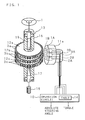
- FIG. 1 is a schematic view showing the configurations of a rotational angle detecting apparatus, a torque detecting apparatus and a steering apparatus in accordance with an embodiment of the present invention, mainly applied to automobiles, for example. In this steering apparatus, an input shaft 16 (a rotating member functioning as a first shaft) whose upper end portion is connected to a steering wheel 1 (a steering member) is coaxially connected to an output shaft 17 (a rotating member functioning as a second shaft) whose lower end portion is connected to a
pinion 18 in a steering mechanism (not shown) via a torsion bar 19 (a connecting shaft) having a small diameter, whereby asteering shaft 13 for connecting thesteering wheel 1 to the steering mechanism is formed. The configuration in the vicinity of the connecting portion between theinput shaft 16 and theoutput shaft 17 is described below. - In the vicinity of an end portion of the connecting side of the
input shaft 16 connected to theoutput shaft 17, disc-shaped target plates 12a and 12b are coaxially fitted on theinput shaft 16 and secured thereto with the target plate 12a (a rotating member) disposed on the side of thesteering wheel 1. On the outer circumferential face of the target plate 12a, a plurality of targets 3a (first targets), which are convex portions made of a magnetic material, 36 pieces for example, are provided at equal intervals so as to protrude in the circumferential direction. On the outer circumferential face of thetarget plate 12b (another rotating member), a plurality of targets 3b (second targets), which are convex portions made of a magnetic material, are provided at equal intervals so as to protrude in the circumferential direction. The number of the targets 3b is for example 37, a number being prime to the number of the targets 3a. The fact that two numbers are prime to each other means that they do not have any common divisors other than one. - The targets 3a and 3b are formed of the teeth of spur gears having involute teeth, and the circular spur gears are used to form the
target plates 12a and 12b and the targets 3a and 3b. - In the vicinity of an end portion of the connecting side of the
output shaft 17 connected to theinput shaft 16, atarget plate 12c (a rotating member) provided with 36 targets 3c (first targets) similar to the above-mentioned targets 3a is also fitted on theoutput shaft 17 and secured thereto. The targets 3c of thetarget plate 12c on the side of theoutput shaft 17 and the targets 3a of the target plate 12a on the side of theinput shaft 16 are aligned in the circumferential direction and provided in parallel. - The teeth serving as the targets 3a, 3b and 3c may be formed by gear cutting the circumferential faces of the
input shaft 16 and theoutput shaft 17 made of a magnetic material. - Outside the
target plates input shaft 16 and theoutput shaft 17.Magnetic sensors input shaft 16 and themagnetic sensors output shaft 17 are correctly aligned in the circumferential direction and contained inside the sensor box 11a. In addition,magnetic sensors 3A and 3B (third detecting means and fourth detecting means) disposed at different positions opposite to each other in the circumferential direction of the targets 3b on the side of theinput shaft 16 are also contained therein. - The
magnetic sensors magnetic sensors operation circuit 10 comprises a microprocessor provided inside or outside the sensor box 11a. - The
operation circuit 10 includes a table 14 in which the rotational angle of theinput shaft 16 at the time of its rotation and the previously measured detection signal values of themagnetic sensors - The
magnetic sensors - The operations of the rotational angle detecting apparatus and the torque detecting apparatus having the above-mentioned configurations will be described below.
- The
magnetic sensors input shaft 16 and theoutput shaft 17 as shown in FIG. 2A, FIG. 2B and FIG. 2C, respectively, while the targets 3a, 3c and 3b pass by the positions opposite to the corresponding sensors, respectively. - The detection signals of the
magnetic sensors input shaft 16 provided with the targets 3a disposed opposite to these magnetic sensors. The detection signals of themagnetic sensors 3A and 3B correspond to the rotational angle of theinput shaft 16 provided with the targets 3b disposed opposite to these magnetic sensors. The detection signals of themagnetic sensors output shaft 17 provided with the targets 3c disposed opposite to these magnetic sensors. - Hence, the
operation circuit 10 can calculate the relative rotational angle of theinput shaft 16 from the detection signals of themagnetic sensors operation circuit 10 and themagnetic sensors input shaft 16. In addition, theoperation circuit 10 can calculate the relative rotational angle of theoutput shaft 17 from the detection signals of themagnetic sensors operation circuit 10 and themagnetic sensors output shaft 17. - When a torque is applied to the
input shaft 16, a difference occurs between each of the detection signals of themagnetic sensors magnetic sensors - The
magnetic sensors magnetic sensors target plates 12a and 12c, respectively. The nonlinear change rate of each of the detection signals is maximized at maximal and minimal values as turning points of rising and lowering. Because of the difference in phase, interpolation is possible with each other. In the case when interpolation is possible, the difference in phase may be any electrical angle of 1° to less than 360°. - The difference between the detection signal of the
magnetic sensor 1A and the detection signal of themagnetic sensor 2A or the difference between the detection signal of themagnetic sensor 1B and the detection signal of themagnetic sensor 2B corresponds to the difference (relative angle displacement) between the rotational angle of theinput shaft 16 and the rotational angle of theoutput shaft 17. This relative angle displacement corresponds to a torsional angle generating in atorsion bar 19 connected between theinput shaft 16 and theoutput shaft 17 when torque is applied to theinput shaft 16. As a result, the torque applied to theinput shaft 16 can be calculated on the basis of the difference between the above-mentioned detection signals. - Furthermore, just like the
magnetic sensors magnetic sensors 3A and 3B are different in phase from each other by an electrical angle of 90° in the circumferential direction of thetarget plate 12b. Although the number of the targets 3a disposed opposite to themagnetic sensors magnetic sensors 3A and 3B is 37. Hence, each time theinput shaft 16 rotates by one phase amount, the phases of the detection signals outputted from themagnetic sensors 1A and 3A and the phases of the detection signals outputted from themagnetic sensors - In the case when only the
magnetic sensors 1A and 3A or only themagnetic sensors input shaft 16 rotates 360° as shown in FIG. 3. Hence, the rotational angle (absolute rotational angle) of theinput shaft 16 cannot be specified. However, the rotational angle of theinput shaft 16 can be specified by referring to the detection signal values of themagnetic sensors - In addition, the number of the targets disposed opposite to the
magnetic sensors 3A and 3B serving as absolute angle (detection) sensors is different from the number of the targets disposed opposite to themagnetic sensors magnetic sensors magnetic sensors 3A and 3B is different from that of themagnetic sensors magnetic sensors - In the case when an absolute rotational angle is detected, the absolute rotational angle of the
input shaft 16 or the absolute rotational angle of theoutput shaft 17 is detected depending on the type of vehicle to which the steering apparatus is applied. - In the case of the steering apparatus for detecting the absolute rotational angle of the
input shaft 16, a target plate for absolute angle (detection), such as thetarget plate 12b, and a target plate for input (shaft) relative angle (detection), such as the target plate 12a, can be arranged on theinput shaft 16 in this order from above, and a target plate for output (shaft) relative angle (detection), such as thetarget plate 12c, can be arranged on theoutput shaft 17, as shown in a schematic view of FIG. 4A. - In the case of the steering apparatus for detecting the absolute rotational angle of the
output shaft 17, the target plate for input (shaft) relative angle (detection) can be arranged on theinput shaft 16, and the target plate for output (shaft) relative angle (detection) and the target plate for absolute angle (detection) can be arranged on theoutput shaft 17 in this order from above, as shown in a schematic view of FIG. 4B. - However, if the target plates are arranged as shown in the schematic views of FIG. 4A and FIG. 4B, the arrangement positions of the absolute angle (detection) sensors in a sensor box, such as the sensor box 11a, must be changed up and down in each of the above-mentioned arrangement cases. It is thus necessary to produce two kinds of sensor boxes.
- Furthermore, in the case of the steering apparatus for detecting the absolute rotational angle of the
input shaft 16, the target plate for input (shaft) relative angle (detection) and the target plate for absolute angle (detection) can be arranged on theinput shaft 16 in this order from above, and the target plate for output (shaft) relative angle (detection) can be arranged on theoutput shaft 17, as shown in a schematic view of FIG. 4C. - Moreover, in the case of the steering apparatus for detecting the absolute rotational angle of the
output shaft 17, the target plate for input (shaft) relative angle (detection) can be arranged on theinput shaft 16, and the target plate for absolute angle (detection) and the target plate for output (shaft) relative angle (detection) can be arranged on theoutput shaft 17 in this order from above. - In any of the above-mentioned cases, by arranging the target plate for input (shaft) relative angle (detection), the target plate for absolute angle (detection) and the target plate for output (shaft) relative angle (detection) in this order from above so that the target plate for absolute angle (detection) is provided between the two target plates for relative angle (detection), it is not necessary to change the arrangement positions of the absolute angle (detection) sensors in the sensor box, whereby only one kind of sensor box is required to be produced.
- The above-mentioned targets are not particularly limited in configuration, provided that the detection signals of the magnetic sensors change as the target plates (rotating members) rotate. For example, the
target plates target plates target plates input shaft 16 can be detected, just as in the case of the above-mentioned gear-type target plates. - Furthermore, instead of the
target plates target plates 12e, 12f and 12g provided with concave portions 3eo, 3fo and 3go, respectively, so as to form non-concave portions 3e, 3f and 3g at nearly equal intervals in the circumferential directions of the outer circumferential surfaces of the target plate as shown in FIG. 5. In this embodiment, the concave portions 3eo, 3fo and 3go are through holes. - Since the non-concave portions 3e, 3f and 3g and the concave portions 3eo, 3fo and 3go alternately become close to the
magnetic sensors magnetic sensors - In addition, instead of the
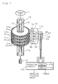
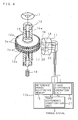
target plates target plates 12h, 12i and 12j whose outercircumferential surfaces 3h, 3i and 3j are magnetized so as to be reversed alternately in polarity at nearly equal intervals in the circumferential directions thereof as shown in FIG. 6. Since the magnetic poles close to themagnetic sensors target plates 12h, 12i and 12j rotate, the intensity of the magnetic field detected depending on the change in the distance between each of themagnetic sensors - FIG. 7 is a schematic view showing the configurations of a rotational angle detecting apparatus, a torque detecting apparatus and a steering apparatus in accordance with another embodiment. In this steering apparatus,
target plates 12c and 12d are fitted coaxially on theoutput shaft 17 of the torque detecting apparatus and the steering apparatus described in FIG. 1 and secured thereto with thetarget plate 12c disposed on the side of thesteering wheel 1, whereby an output shaft 17a is formed. On the outer circumferential surface of the target plate 12d, a plurality of targets 3d, which are convex portions made of a magnetic material, 37 pieces for example, protrude at equal intervals in the circumferential direction. - The targets 3c of the
target plate 12c on the side of the output shaft 17a and the targets 3a of the target plate 12a on the side of theinput shaft 16 are aligned in the circumferential direction and provided in parallel. - The number of the targets 3c (teeth) is different from the number of the targets 3d (teeth) by one.
- Outside the
target plates sensor box 11b is disposed so as to face the outer fringes of the targets 3a, 3b, 3c and 3d formed on the outer circumferences of the target plates, respectively. Thesensor box 11b is secured to and supported by a stationary portion, such as a housing, for rotatably supporting theinput shaft 16 and the output shaft 17a. Themagnetic sensors magnetic sensors 3A and 3B disposed at different positions opposite to each other in the circumferential direction of the targets 3b on the side of theinput shaft 16, and themagnetic sensors sensor box 11b. - The magnetic sensors 4A and 4B are similar to the
magnetic sensors magnetic sensors sensor box 11b. - The operation circuit 10a includes a table 14a (identical to the table 14 of FIG. 1) in which the rotational angle of the
input shaft 16 at the time of its rotation and the measured detection signal values of themagnetic sensors magnetic sensors - The
magnetic sensors - The operations of the rotational angle detecting apparatus, the torque detecting apparatus and the steering apparatus having the above-mentioned configurations will be described below.
- The
magnetic sensors input shaft 16 and the output shaft 17a as shown in FIG. 2A, while the targets 3a, 3c, 3b and 3d pass by the positions opposite to the corresponding sensors. - The detection signals of the magnetic sensors 4A and 4B correspond to the rotational angle of the output shaft 17a provided with the targets 3d disposed opposite to these magnetic sensors.
- Furthermore, just like the
magnetic sensors magnetic sensors input shaft 16 rotates by one phase amount, the phases of the detection signals outputted from themagnetic sensors 2A and 4A and the phases of the detection signals outputted from of themagnetic sensors 2B and 4B are displaced from each other by a 1/37 phase amount as shown in FIG. 3. - In the case when only the
magnetic sensors 2A and 4A or only themagnetic sensors 2B and 4B are used, one set of the same detection signal values generates twice while theinput shaft 16 rotates 360° as shown in FIG. 3. Hence, the rotational angle (absolute rotational angle) of theinput shaft 16 cannot be specified. However, the rotational angle of theinput shaft 16 can be specified by referring to the detection signal values of themagnetic sensors - When the
magnetic sensors channels faulty channels 1A and/or 1B are specified, and the torque can be detected by thechannels 3A, 3B, 4A and 4B, and the rotational angle (absolute rotational angle) can be detected by thechannels - In other words, even if any one of the eight channels, i.e., the eight magnetic sensors, becomes faulty, the steering apparatus operates without problems, and the fault can be notified (a diagnosis signal is outputted), and the absolute rotational angle of the input shaft or the output shaft can be detected continuously.
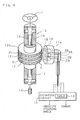
- FIG. 8 is a schematic view showing the configurations of a torque detecting apparatus and a steering apparatus in accordance with still another embodiment. In the torque detecting apparatus and the steering apparatus, the
target plate 12b is eliminated from theinput shaft 16 of the rotational angle detecting apparatus, the torque detecting apparatus and the steering apparatus described in FIG. 1, whereby an input shaft 16a is formed. - Outside the
target plates 12a and 12c, asensor box 11 is disposed so as to face the outer fringes of the targets 3a and 3c on the outer circumferences of thetarget plates 12a and 12c, respectively. Thesensor box 11 is secured to and supported by a stationary portion, such as a housing, for rotatably supporting the input shaft 16a and theoutput shaft 17. Themagnetic sensors magnetic sensors output shaft 17 are correctly aligned in the corresponding respective circumferential directions and contained inside thesensor box 11. - The detection signals of the
magnetic sensors operation circuit 10b comprises a microprocessor provided inside or outside thesensor box 11. - The
operation circuit 10b is provided with a referencephase difference memory 15 for storing the displacement of the phase difference between the targets 3a and 3c at the time when the torsion of thetorsion bar 19 measured during assembly is zero, a phasedifference operation unit 20 for operating the phase difference between the targets 3a and 3c on the basis of the detection signals of themagnetic sensors difference operation unit 20 and the displacement of the phase difference stored in the referencephase difference memory 15. Theoperation circuit 10b outputs a torque signal based on the phase difference compensated for by the phase difference compensation unit 21. The other configurations of the torque detecting apparatus and the steering apparatus are similar to those of the torque detecting apparatus and the steering apparatus described in to FIG. 1. Hence, the same elements are designated by the same reference numerals, and their explanations are omitted. - The operations of the torque detecting apparatus and the steering apparatus having the above-mentioned configurations will be described below.
- In the case when the number of the teeth, i.e., the targets 3a and 3c, is 40 (9° for one period), for example, and when the left/right torsional angles (mechanical stopper angles) of the
torsion bar 19 are ±4°, for example, no difference occurs between the left/right torque values as shown in FIG. 9A, provided that no error is present in the assembly of thetarget plates 12a and 12c and the input/output shafts 16a and 17. - Since one period corresponds to 9°, a torsional angle of +4.5° and a torsional angle of -4.5° are the same as phase difference signals. Furthermore, a torsional angle of -4° and a torsional angle of +5° are also the same as phase difference signals.
- For example, in the case when an assembly error is present between the
target plates 12a and 12c (an error of 1°, for example) and when thetorsion bar 19 is pinned and secured to the input shaft 16a and theoutput shaft 17 so that the phase difference between the input shaft 16a and theoutput shaft 17 becomes zero, a deviation occurs in the phase difference (torque) between the targets 3a and 3c. - When the deviations are -3° and +5° as shown in FIG. 9B, right/left turnover of torque occurs (a counter torque generates) in the range of +4.5° to +5°. In other words, it is impossible to distinguish between α° and (9 + α)°.
- To solve this problem, while the displacement (1°, for example) (the assembly error between the
target plates 12a and 12c) of the phase difference between the targets 3a and 3c is unchanged as shown in FIG. 9C, pinning is carried out at the neutral point of a mechanical stopper, the displacement of the phase difference between the targets 3a and 3c is measured, and the phase difference is stored in the referencephase difference memory 15. - During operation, the phase
difference operation unit 20 performs an operation to obtain the phase difference between the targets 3a and 3c on the basis of the detection signals of themagnetic sensors phase difference memory 15 and outputs a torque signal based on the compensated phase difference. - As a result, it is possible to ignore the displacement of the phase difference between the targets 3a and 3c (the assembly error between the
target plates 12a and 12c). In addition, the range of torque detection is expanded, any mechanical phase difference is eliminated, phase alignment work is not necessary, and the number of targets (teeth) is not required to be reduced, thereby being advantageous in resolution and accuracy. - The other operations of the torque detecting apparatus and the steering apparatus are similar to those (except the operation for detecting the absolute steering angle) of the torque detecting apparatus and the steering apparatus described in to FIG. 1. Hence, the same elements are designated by the same reference numerals, and their explanations are omitted.
- With the rotational angle detecting apparatus in accordance with the first aspect, the first detecting means, the second detecting means, the third detecting means and the fourth detecting means output sinusoidal detection signals respectively, whereby it is possible to realize a rotational angle detecting apparatus capable of detecting an absolute rotational angle.
- With the rotational angle detecting apparatuses in accordance with the second and third aspects, it is possible to realize rotational angle detecting apparatuses capable of detecting an absolute rotational angle.
- With the rotational angle detecting apparatus in accordance with the fourth aspect, as the rotating members rotate, the first detecting means, the second detecting means, the third detecting means and the fourth detecting means output the sinusoidal detection signals periodically, whereby it is possible to realize a rotational angle detecting apparatus capable of detecting an absolute rotational angle.
- With the torque detecting apparatus in accordance with the fifth aspect, it is possible to realize a torque detecting apparatus provided with a rotational angle detecting apparatus capable of detecting an absolute rotational angle.
- With the torque detecting apparatus in accordance with the sixth aspect, even if the second targets are provided on either side of the first shaft or the second shaft, the arrangement positions of the first detecting means, the second detecting means, the third detecting means and the fourth detecting means can be determined so as to have one arrangement order, whereby the cost of producing the apparatus can be reduced.
- With the steering apparatus in accordance with the seventh aspect, it is possible to realize a steering apparatus provided with the torque detecting apparatus in accordance with the fifth or sixth aspect.
Claims (7)
- A rotational angle detecting apparatus comprising rotating member; one or more first targets provided on said rotating member; first detecting means, disposed opposite to said first targets, for outputting a detection signal as said rotating member rotates; and second detecting means for outputting a detection signal having a phase different from that of the detection signal of said first detecting means, whereby the rotational angle of said rotating member is detected on the basis of the detection signals outputted by said first detecting means and said second detecting means, characterized by comprising:second targets (3b; 3f; 3i; 3fo), the number of which is prime to the number of said first targets (3a, 3c; 3e, 3g; 3h, 3j; 3eo, 3go), provided on said rotating member (16; 17) or other rotating members (12b; 12f, 12i) rotating coaxially with said rotating member (16; 17);third detecting means (3A), disposed opposite to said second targets (3b; 3f; 3i; 3fo), for outputting a detection signal as the rotating member (16; 17) rotates; andfourth detecting means (3B) for outputting a detection signal having a phase different from that of the detection signal of said third detecting means (3A); whereinthe rotational angle of said rotating member (16; 17) is detected on the basis of the detection signals outputted by said first detecting means (1A, 2A), said second detecting means (1B, 2B), said third detecting means (3A) and said fourth detecting means (3B).
- A rotational angle detecting apparatus as set forth in claim 1, characterized in that said first targets (3a, 3c) and said second targets (3b) are formed of convex portions (3a, 3c, 3b) provided at nearly equal intervals in the circumferential directions of said rotating members (16; 17, 12b).
- A rotational angle detecting apparatus as set forth in claim 1, characterized in that said first targets (3e, 3g, 3eo, 3go) and said second targets (3f, 3fo) are formed of non-concave portions (3e, 3g, 3f) provided between concave portions (3eo, 3go) provided so that said non-concave portions (3e, 3g, 3f) are formed at nearly equal intervals in the circumferential directions of said rotating members (16; 17, 12f).
- A rotational angle detecting apparatus as set forth in claim 1, characterized in that said first targets (3h, 3j) and said second targets (3i) are provided with magnetic poles magnetized so as to be reversed alternately in polarity at nearly equal intervals in the circumferential directions of said rotating members (16; 17, 12i).
- A torque detecting apparatus characterized in that:said rotational angle detecting apparatus as set forth in any one of claims 1 through 4 is provided for a first shaft (16) or a second shaft (17) connected via a connecting shaft (19),said first targets (3a, 3c; 3e, 3g; 3h, 3j; 3eo, 3go), said first detecting means (1A, 2A) and said second detecting means (1B, 2B) are provided for said second shaft (17) or said first shaft (16), andtorque applied to said first shaft (16) is detected on the basis of the difference between the detection signal outputted by said first detecting means (1A, 2A) or said second detecting means (1B, 2B) provided for said first shaft (16) and the detection signal outputted by said first detecting means (1A, 2A) or said second detecting means (1B, 2B) provided for said second shaft (17) depending on torsion generating in said connecting shaft (19).
- A torque detecting apparatus as set forth in claim 5, characterized in that said second targets (3b; 3f; 3i; 3fo) provided in said rotational angle detecting apparatus are provided between said first targets (3a, 3e, 3h, 3eo) provided on said first shaft (16) and said first targets (3c, 3g, 3j, 3go) provided on said second shaft (17).
- A steering apparatus characterized by comprising:a first shaft (16) connected to a steering member (1):a second shaft (17) connected to a steering mechanism (18);a connecting shaft (19) for connecting said first shaft (16) and said second shaft (17); andsaid torque detecting apparatus, as set forth in claim 5 or 6, for detecting steering torque applied to said first shaft (16) on the basis of a torsional angle generating in said connecting shaft (19); wherebysteering assisting is carried out depending on the steering torque detected by said torque detecting apparatus.
Applications Claiming Priority (2)
| Application Number | Priority Date | Filing Date | Title |
|---|---|---|---|
| JP2002069121 | 2002-03-13 | ||
| JP2002069121A JP2003270062A (en) | 2002-03-13 | 2002-03-13 | Angle-of-rotation detecting device, torque detecting device, and steering system |
Publications (3)
| Publication Number | Publication Date |
|---|---|
| EP1344711A2 true EP1344711A2 (en) | 2003-09-17 |
| EP1344711A3 EP1344711A3 (en) | 2003-11-05 |
| EP1344711B1 EP1344711B1 (en) | 2007-08-15 |
Family
ID=27764521
Family Applications (1)
| Application Number | Title | Priority Date | Filing Date |
|---|---|---|---|
| EP03005521A Expired - Lifetime EP1344711B1 (en) | 2002-03-13 | 2003-03-11 | Rotational angle detecting apparatus, torque detecting apparatus and steering apparatus |
Country Status (5)
| Country | Link |
|---|---|
| US (1) | US6935195B2 (en) |
| EP (1) | EP1344711B1 (en) |
| JP (1) | JP2003270062A (en) |
| KR (1) | KR100807179B1 (en) |
| DE (1) | DE60315534T2 (en) |
Cited By (9)
| Publication number | Priority date | Publication date | Assignee | Title |
|---|---|---|---|---|
| EP1364859A3 (en) * | 2002-05-23 | 2004-06-23 | Koyo Seiko Co., Ltd. | Rotational angle detecting apparatus and torque detecting apparatus |
| EP1516799A1 (en) * | 2003-09-18 | 2005-03-23 | Toyoda Koki Kabushiki Kaisha | Electric power steering apparatus and angle compensating method therefor |
| WO2005068962A1 (en) | 2004-01-20 | 2005-07-28 | Valeo Schalter Und Sensoren Gmbh | Device for determining a steering angle and a torque that is exerted on a steering shaft |
| EP1647816A1 (en) * | 2004-10-15 | 2006-04-19 | Bei Sensors And Systems Company, Inc. | Digitally compensated non-contact steering angle and torque sensor |
| EP1752361A1 (en) * | 2005-08-11 | 2007-02-14 | ZF Lenksysteme GmbH | Shaft torque and position sensor |
| EP1977952A3 (en) * | 2002-05-27 | 2008-10-22 | JTEKT Corporation | Electric power steering apparatus |
| EP2116813A4 (en) * | 2007-02-23 | 2012-07-11 | Ntn Toyo Bearing Co Ltd | ROTATION DETECTION DEVICE AND BEARING WITH ROTATION DETECTION DEVICE |
| EP3009666A1 (en) * | 2014-10-16 | 2016-04-20 | MAN Truck & Bus AG | Crankshaft starter generator |
| EP3037796A1 (en) * | 2014-12-23 | 2016-06-29 | Samson Aktiengesellschaft | Spring body for a force transducer, such as torque and/or tensile/compression force measuring cell |
Families Citing this family (22)
| Publication number | Priority date | Publication date | Assignee | Title |
|---|---|---|---|---|
| JP4474872B2 (en) * | 2003-09-02 | 2010-06-09 | パナソニック株式会社 | Absolute rotation angle and torque detector |
| DE102004053690A1 (en) * | 2004-11-06 | 2006-05-11 | Zf Lenksysteme Gmbh | Method and device for determining a steering angle of a vehicle |
| JP4574406B2 (en) * | 2005-03-18 | 2010-11-04 | 株式会社小松製作所 | Stroke position measuring device of hydraulic cylinder in hydraulic work machine |
| JP2007183121A (en) * | 2006-01-05 | 2007-07-19 | Matsushita Electric Ind Co Ltd | Rotation angle and torque detection device |
| JP5081553B2 (en) * | 2007-09-27 | 2012-11-28 | Ntn株式会社 | Rotation detection device and bearing with rotation detection device |
| JP5221494B2 (en) * | 2008-12-24 | 2013-06-26 | Ntn株式会社 | Rotation detection device and bearing with rotation detection device |
| JP5671255B2 (en) * | 2009-06-30 | 2015-02-18 | Ntn株式会社 | Rotation angle detection device for motor for driving automobile and bearing with rotation angle detection device |
| FR2947902B1 (en) * | 2009-07-07 | 2011-07-22 | Moving Magnet Technologies M M T | ABSOLUTE AND MULTI-PERIODIC POSITION SENSOR |
| JP5256174B2 (en) * | 2009-11-19 | 2013-08-07 | 山洋電気株式会社 | Magnetic absolute encoder |
| JP5434850B2 (en) * | 2010-08-19 | 2014-03-05 | Tdk株式会社 | Rotation angle / torque sensor |
| JP5545121B2 (en) * | 2010-08-19 | 2014-07-09 | Tdk株式会社 | Rotation angle / torque sensor |
| CN103675337B (en) * | 2012-09-19 | 2016-02-03 | 财团法人车辆研究测试中心 | Non-contact steering sensing method and device |
| KR101512225B1 (en) * | 2013-03-26 | 2015-04-17 | 주식회사 만도 | Method for providing reliability of torque and control apparatus |
| DE102014220783A1 (en) * | 2014-10-14 | 2016-04-14 | Robert Bosch Gmbh | Sensor for determining at least one rotational property of a rotating element |
| KR101671634B1 (en) * | 2015-06-08 | 2016-11-02 | 현대로템 주식회사 | Method for determining the amount of wear quantity for shaft parts of power transmission system |
| DE102016205781A1 (en) * | 2016-04-07 | 2017-10-12 | Voith Patent Gmbh | Method and device for determining a relative angular position of rotating components |
| US11385078B2 (en) * | 2018-11-23 | 2022-07-12 | Samsung Electro-Mechanics Co., Ltd. | Rotation sensing apparatus |
| DE102019201676A1 (en) * | 2019-02-08 | 2020-08-13 | Zf Friedrichshafen Ag | Arrangement Determining an angle of rotation and electrical machine |
| US11808014B2 (en) | 2020-10-12 | 2023-11-07 | Deere & Company | Work machines incorporating encoder systems, drive assemblies therefor, and methods of measuring torque using encoder systems |
| DE102020006829A1 (en) | 2020-11-06 | 2022-05-12 | Lenord, Bauer & Co.Gmbh | Method and device for determining an absolute rotational position of a shaft |
| DE102021208762A1 (en) | 2021-08-11 | 2023-02-16 | Zf Friedrichshafen Ag | Device and method for determining an angular position of a rotatably mounted object |
| WO2023115525A1 (en) * | 2021-12-24 | 2023-06-29 | 浙江大学台州研究院 | Angle and torque measurement system for high-voltage large-current switching-out device |
Citations (1)
| Publication number | Priority date | Publication date | Assignee | Title |
|---|---|---|---|---|
| JP2001292534A (en) | 2000-04-04 | 2001-10-19 | Sekisui Chem Co Ltd | Deterioration determination device for lithium ion battery |
Family Cites Families (14)
| Publication number | Priority date | Publication date | Assignee | Title |
|---|---|---|---|---|
| JPS62168019A (en) * | 1986-01-20 | 1987-07-24 | Hitachi Ltd | Magnetic rotary sensor |
| KR890000890A (en) * | 1987-06-22 | 1989-03-17 | 미타 가츠시게 | Torque Detection Device |
| JPH01270627A (en) * | 1988-04-22 | 1989-10-27 | Hitachi Ltd | Torque sensor protection device |
| JPH01297507A (en) * | 1988-05-26 | 1989-11-30 | Hitachi Ltd | Device that magnetically detects position and speed |
| JP2515891B2 (en) * | 1989-09-20 | 1996-07-10 | 株式会社日立製作所 | Angle sensor, torque sensor, and electric power steering device controlled according to the outputs of the sensors |
| JPH0943260A (en) * | 1995-08-03 | 1997-02-14 | Nissan Motor Co Ltd | MR element type rotation sensor |
| DE19601674B4 (en) * | 1996-01-18 | 2005-08-04 | Valeo Schalter Und Sensoren Gmbh | According to Differenzmeßprinzip working steering angle sensor for motor vehicles |
| DE19745823A1 (en) * | 1997-10-16 | 1999-04-29 | Sensor Instr Gmbh | Torque and rotation angle measuring device e.g. for motor vehicle |
| US6295879B1 (en) * | 1999-03-08 | 2001-10-02 | Trw Inc. | Torque sensing apparatus for an electric assist steering system |
| US20020124663A1 (en) * | 1999-04-07 | 2002-09-12 | Yoshitomo Tokumoto | Rotational angle detecting device, torque detecting device and steering apparatus |
| JP2001201313A (en) * | 1999-10-15 | 2001-07-27 | Koyo Seiko Co Ltd | Rotation angle detection device, torque detection device and steering device |
| JP3681324B2 (en) * | 2000-07-14 | 2005-08-10 | 光洋精工株式会社 | Torque detection device and electric power steering device |
| DE10036281A1 (en) * | 2000-07-26 | 2002-02-07 | Bosch Gmbh Robert | Determination of a rotating axle angular position by use of two signal wheels with signal tracks comprised of magnetic poles the signal tracks of which are detected by sensors linked to an analysis device for high resolution |
| JP3784248B2 (en) * | 2000-10-02 | 2006-06-07 | 株式会社ジェイテクト | Rotation angle detection device, torque sensor and steering device |
-
2002
- 2002-03-13 JP JP2002069121A patent/JP2003270062A/en not_active Withdrawn
-
2003
- 2003-03-11 DE DE60315534T patent/DE60315534T2/en not_active Expired - Fee Related
- 2003-03-11 EP EP03005521A patent/EP1344711B1/en not_active Expired - Lifetime
- 2003-03-13 US US10/388,734 patent/US6935195B2/en not_active Expired - Fee Related
- 2003-03-13 KR KR1020030015602A patent/KR100807179B1/en not_active Expired - Fee Related
Patent Citations (1)
| Publication number | Priority date | Publication date | Assignee | Title |
|---|---|---|---|---|
| JP2001292534A (en) | 2000-04-04 | 2001-10-19 | Sekisui Chem Co Ltd | Deterioration determination device for lithium ion battery |
Cited By (14)
| Publication number | Priority date | Publication date | Assignee | Title |
|---|---|---|---|---|
| US7087889B2 (en) | 2002-05-23 | 2006-08-08 | Koyo Seiko Co., Ltd. | Rotational angle detecting apparatus and torque detecting apparatus |
| EP1364859A3 (en) * | 2002-05-23 | 2004-06-23 | Koyo Seiko Co., Ltd. | Rotational angle detecting apparatus and torque detecting apparatus |
| EP1977952A3 (en) * | 2002-05-27 | 2008-10-22 | JTEKT Corporation | Electric power steering apparatus |
| EP1516799A1 (en) * | 2003-09-18 | 2005-03-23 | Toyoda Koki Kabushiki Kaisha | Electric power steering apparatus and angle compensating method therefor |
| US7076352B2 (en) | 2003-09-18 | 2006-07-11 | Toyoda Koki Kabushiki Kaisha | Electric power steering apparatus and angle compensating method therefor |
| EP1706716B1 (en) * | 2004-01-20 | 2011-09-14 | Valeo Schalter und Sensoren GmbH | Device for determining a steering angle and a torque that is exerted on a steering shaft |
| WO2005068962A1 (en) | 2004-01-20 | 2005-07-28 | Valeo Schalter Und Sensoren Gmbh | Device for determining a steering angle and a torque that is exerted on a steering shaft |
| EP1647816A1 (en) * | 2004-10-15 | 2006-04-19 | Bei Sensors And Systems Company, Inc. | Digitally compensated non-contact steering angle and torque sensor |
| EP1752361A1 (en) * | 2005-08-11 | 2007-02-14 | ZF Lenksysteme GmbH | Shaft torque and position sensor |
| EP2116813A4 (en) * | 2007-02-23 | 2012-07-11 | Ntn Toyo Bearing Co Ltd | ROTATION DETECTION DEVICE AND BEARING WITH ROTATION DETECTION DEVICE |
| EP3009666A1 (en) * | 2014-10-16 | 2016-04-20 | MAN Truck & Bus AG | Crankshaft starter generator |
| RU2700808C2 (en) * | 2014-10-16 | 2019-09-23 | Ман Трак Унд Бас Аг | Crankshaft starter generator |
| EP3037796A1 (en) * | 2014-12-23 | 2016-06-29 | Samson Aktiengesellschaft | Spring body for a force transducer, such as torque and/or tensile/compression force measuring cell |
| US10001419B2 (en) | 2014-12-23 | 2018-06-19 | Samson Aktiengesellschaft | Spring body for a force transducer, such as a torque-and/or tension/compression-force measuring cell |
Also Published As
| Publication number | Publication date |
|---|---|
| KR100807179B1 (en) | 2008-02-27 |
| DE60315534D1 (en) | 2007-09-27 |
| US20030192386A1 (en) | 2003-10-16 |
| DE60315534T2 (en) | 2008-04-30 |
| JP2003270062A (en) | 2003-09-25 |
| EP1344711A3 (en) | 2003-11-05 |
| EP1344711B1 (en) | 2007-08-15 |
| US6935195B2 (en) | 2005-08-30 |
| KR20030074405A (en) | 2003-09-19 |
Similar Documents
| Publication | Publication Date | Title |
|---|---|---|
| EP1344711B1 (en) | Rotational angle detecting apparatus, torque detecting apparatus and steering apparatus | |
| US7677114B2 (en) | Torque sensor for electric power steering system | |
| EP2674728A2 (en) | Rotation angle sensor | |
| CN101893423B (en) | Multi-rotation angle detection device | |
| KR20030028704A (en) | Rotational angle detecting device, Torque detecting device and steering apparatus | |
| JP2008241411A (en) | Rudder angle detector | |
| EP1364859B1 (en) | Rotational angle detecting apparatus and torque detecting apparatus | |
| US9057652B2 (en) | Torque detecting apparatus | |
| JP4085763B2 (en) | Steering state detection device | |
| EP1364860B1 (en) | Rotational angle detecting apparatus and torque detecting apparatus | |
| JP4982925B2 (en) | Rotation angle detector | |
| US6983664B2 (en) | Rotation angle detecting device, and torque detecting device | |
| US7201070B2 (en) | Rotational angle detecting apparatus and torque detecting apparatus | |
| JP6108009B2 (en) | Relative angle detection device, torque sensor, electric power steering device, and vehicle | |
| JP4872229B2 (en) | Vehicle steering system | |
| EP1295780A2 (en) | Rotational angle detecting device, torque detecting device and steering apparatus | |
| EP1260425B1 (en) | Rotational angle detecting device, torque detecting device and steering apparatus | |
| JP2011080783A (en) | Relative angle detector, rotation angle detector, and power steering device | |
| JP2004156961A (en) | Rotation angle sensitive device and torque sensing device | |
| JP2002120738A (en) | Rotation angle sensing device, torque sensing device, and steering device | |
| JP2004226355A (en) | Rotation angle detecting device | |
| JP2005195362A (en) | Rotation angle detector and torque detector | |
| JP2008051702A (en) | Torque detection device | |
| JP2002350252A (en) | Rotation angle detector, torque detector, and steering device | |
| JP2000121462A (en) | Torque sensor and steering device |
Legal Events
| Date | Code | Title | Description |
|---|---|---|---|
| PUAI | Public reference made under article 153(3) epc to a published international application that has entered the european phase |
Free format text: ORIGINAL CODE: 0009012 |
|
| AK | Designated contracting states |
Kind code of ref document: A2 Designated state(s): AT BE BG CH CY CZ DE DK EE ES FI FR GB GR HU IE IT LI LU MC NL PT RO SE SI SK TR |
|
| AX | Request for extension of the european patent |
Extension state: AL LT LV MK |
|
| PUAL | Search report despatched |
Free format text: ORIGINAL CODE: 0009013 |
|
| AK | Designated contracting states |
Kind code of ref document: A3 Designated state(s): AT BE BG CH CY CZ DE DK EE ES FI FR GB GR HU IE IT LI LU MC NL PT RO SE SI SK TR |
|
| AX | Request for extension of the european patent |
Extension state: AL LT LV MK |
|
| 17P | Request for examination filed |
Effective date: 20031224 |
|
| AKX | Designation fees paid |
Designated state(s): DE FR IT |
|
| RAP1 | Party data changed (applicant data changed or rights of an application transferred) |
Owner name: JTEKT CORPORATION |
|
| GRAP | Despatch of communication of intention to grant a patent |
Free format text: ORIGINAL CODE: EPIDOSNIGR1 |
|
| GRAS | Grant fee paid |
Free format text: ORIGINAL CODE: EPIDOSNIGR3 |
|
| RIN1 | Information on inventor provided before grant (corrected) |
Inventor name: SHIBA, MAHITOJTEKT CORPORATION Inventor name: MAEDA, NAOKIJTEKT CORPORATION Inventor name: TOKUMOTO, YOSHITOMOJTEKT CORPORATION |
|
| GRAC | Information related to communication of intention to grant a patent modified |
Free format text: ORIGINAL CODE: EPIDOSCIGR1 |
|
| GRAA | (expected) grant |
Free format text: ORIGINAL CODE: 0009210 |
|
| AK | Designated contracting states |
Kind code of ref document: B1 Designated state(s): DE FR IT |
|
| REF | Corresponds to: |
Ref document number: 60315534 Country of ref document: DE Date of ref document: 20070927 Kind code of ref document: P |
|
| ET | Fr: translation filed | ||
| PGFP | Annual fee paid to national office [announced via postgrant information from national office to epo] |
Ref country code: IT Payment date: 20080321 Year of fee payment: 6 |
|
| PLBE | No opposition filed within time limit |
Free format text: ORIGINAL CODE: 0009261 |
|
| STAA | Information on the status of an ep patent application or granted ep patent |
Free format text: STATUS: NO OPPOSITION FILED WITHIN TIME LIMIT |
|
| 26N | No opposition filed |
Effective date: 20080516 |
|
| PGFP | Annual fee paid to national office [announced via postgrant information from national office to epo] |
Ref country code: FR Payment date: 20080311 Year of fee payment: 6 Ref country code: DE Payment date: 20080306 Year of fee payment: 6 |
|
| REG | Reference to a national code |
Ref country code: FR Ref legal event code: ST Effective date: 20091130 |
|
| PG25 | Lapsed in a contracting state [announced via postgrant information from national office to epo] |
Ref country code: DE Free format text: LAPSE BECAUSE OF NON-PAYMENT OF DUE FEES Effective date: 20091001 |
|
| PG25 | Lapsed in a contracting state [announced via postgrant information from national office to epo] |
Ref country code: FR Free format text: LAPSE BECAUSE OF NON-PAYMENT OF DUE FEES Effective date: 20091123 |
|
| PG25 | Lapsed in a contracting state [announced via postgrant information from national office to epo] |
Ref country code: IT Free format text: LAPSE BECAUSE OF NON-PAYMENT OF DUE FEES Effective date: 20090311 |