EP1344691A2 - Arrangement for permitting vehicle foot pedal retraction, and vehicle incorporting same - Google Patents
Arrangement for permitting vehicle foot pedal retraction, and vehicle incorporting same Download PDFInfo
- Publication number
- EP1344691A2 EP1344691A2 EP03251481A EP03251481A EP1344691A2 EP 1344691 A2 EP1344691 A2 EP 1344691A2 EP 03251481 A EP03251481 A EP 03251481A EP 03251481 A EP03251481 A EP 03251481A EP 1344691 A2 EP1344691 A2 EP 1344691A2
- Authority
- EP
- European Patent Office
- Prior art keywords
- rotary member
- push rod
- arrangement
- foot pedal
- vehicle
- Prior art date
- Legal status (The legal status is an assumption and is not a legal conclusion. Google has not performed a legal analysis and makes no representation as to the accuracy of the status listed.)
- Granted
Links
Images

Classifications
-
- G—PHYSICS
- G05—CONTROLLING; REGULATING
- G05G—CONTROL DEVICES OR SYSTEMS INSOFAR AS CHARACTERISED BY MECHANICAL FEATURES ONLY
- G05G1/00—Controlling members, e.g. knobs or handles; Assemblies or arrangements thereof; Indicating position of controlling members
- G05G1/30—Controlling members actuated by foot
- G05G1/32—Controlling members actuated by foot with means to prevent injury
- G05G1/327—Controlling members actuated by foot with means to prevent injury means disconnecting the pedal from its hinge or support, e.g. by breaking or bending the support
-
- B—PERFORMING OPERATIONS; TRANSPORTING
- B60—VEHICLES IN GENERAL
- B60R—VEHICLES, VEHICLE FITTINGS, OR VEHICLE PARTS, NOT OTHERWISE PROVIDED FOR
- B60R21/00—Arrangements or fittings on vehicles for protecting or preventing injuries to occupants or pedestrians in case of accidents or other traffic risks
- B60R21/02—Occupant safety arrangements or fittings, e.g. crash pads
- B60R21/09—Control elements or operating handles movable from an operative to an out-of-the way position, e.g. pedals, switch knobs, window cranks
-
- B—PERFORMING OPERATIONS; TRANSPORTING
- B60—VEHICLES IN GENERAL
- B60T—VEHICLE BRAKE CONTROL SYSTEMS OR PARTS THEREOF; BRAKE CONTROL SYSTEMS OR PARTS THEREOF, IN GENERAL; ARRANGEMENT OF BRAKING ELEMENTS ON VEHICLES IN GENERAL; PORTABLE DEVICES FOR PREVENTING UNWANTED MOVEMENT OF VEHICLES; VEHICLE MODIFICATIONS TO FACILITATE COOLING OF BRAKES
- B60T7/00—Brake-action initiating means
- B60T7/02—Brake-action initiating means for personal initiation
- B60T7/04—Brake-action initiating means for personal initiation foot actuated
- B60T7/06—Disposition of pedal
- B60T7/065—Disposition of pedal with means to prevent injuries in case of collision
-
- Y—GENERAL TAGGING OF NEW TECHNOLOGICAL DEVELOPMENTS; GENERAL TAGGING OF CROSS-SECTIONAL TECHNOLOGIES SPANNING OVER SEVERAL SECTIONS OF THE IPC; TECHNICAL SUBJECTS COVERED BY FORMER USPC CROSS-REFERENCE ART COLLECTIONS [XRACs] AND DIGESTS
- Y10—TECHNICAL SUBJECTS COVERED BY FORMER USPC
- Y10T—TECHNICAL SUBJECTS COVERED BY FORMER US CLASSIFICATION
- Y10T74/00—Machine element or mechanism
- Y10T74/20—Control lever and linkage systems
- Y10T74/20528—Foot operated
-
- Y—GENERAL TAGGING OF NEW TECHNOLOGICAL DEVELOPMENTS; GENERAL TAGGING OF CROSS-SECTIONAL TECHNOLOGIES SPANNING OVER SEVERAL SECTIONS OF THE IPC; TECHNICAL SUBJECTS COVERED BY FORMER USPC CROSS-REFERENCE ART COLLECTIONS [XRACs] AND DIGESTS
- Y10—TECHNICAL SUBJECTS COVERED BY FORMER USPC
- Y10T—TECHNICAL SUBJECTS COVERED BY FORMER US CLASSIFICATION
- Y10T74/00—Machine element or mechanism
- Y10T74/20—Control lever and linkage systems
- Y10T74/20576—Elements
- Y10T74/20888—Pedals
Definitions
- This invention relates in a first aspect to an arrangement for permitting retraction of the foot pedal of a vehicle away from the driver in a crash situation, and whilst the device would normally be effective on the brake pedal, the principles described could be applied to any other pedals (clutch pedal and the accelerator pedal), and in a second aspect to a vehicle incorporating such device.
- EP 1134128 is described an arrangement in which, in a frontal crash situation of sufficient magnitude, the push rod is snapped upon crash induced rotation of a rotary member pivotally attached to the blade of the pedal, to cause decoupling of the push rod from the rotary member and hence freeing of the pedal.
- a basic object of the invention is the provision of an improved arrangement for producing crash induced decoupling of the push rod from the pedal, permitting vehicle foot pedal retraction, and a vehicle incorporating same.
- a motor vehicle comprising an arrangement in accordance with the first aspect.
- the push rod may be of an industry standard construction.
- the rotary member (1) is metallic eg of mild steel, and the decoupling feature (3-8) is provided by the rotary member (1) incorporating an insert (7) of synthetic plastics material, with the insert (7) defining, in part, a bore (8) to receive a portion of the push rod (12), whereby rotation of the rotary member (1) in a crash situation with a torque exceeding a threshold value results in the push rod (12) forcing the insert (7) from the rotary member (1), thereby decoupling the push rod (12) and the pedal blade.
- the rotary member is wholly metallic and the decoupling feature (3, 4, 8) is provided by a zone of weakness.
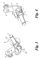
- a rotary member (1) has a pin (2) by which it is pivotally mounted on a blade (13) of a conventional foot pedal.
- the member (1) has a slot (3) with an arcuate end (4), and a pair of opposed grooves (5) in which are located opposed ribs (6) of a synthetic plastics insert (7) also having an arcuate surface (8) to define a circular aperture (9) to receive a portion of a conventional push rod (12) ( Figure 3) of a brake booster or a clutch.
- a lever arm (10) Remote from the pin (2) is a lever arm (10) provided with a pin (11) engageable with a portion of a vehicle designed to crumple in a frontal crash situation of sufficient magnitude, resulting in rotation of the rotary member (1) until sufficient torque results in the insert (7) being forced out of the rotary member (1), so that the push rod is decoupled, and the foot pedal is freed.
Landscapes
- Engineering & Computer Science (AREA)
- Mechanical Engineering (AREA)
- Physics & Mathematics (AREA)
- General Physics & Mathematics (AREA)
- Automation & Control Theory (AREA)
- Transportation (AREA)
- Mechanical Control Devices (AREA)
- Arrangement And Mounting Of Devices That Control Transmission Of Motive Force (AREA)
- Braking Elements And Transmission Devices (AREA)
- Automatic Cycles, And Cycles In General (AREA)
Abstract
Description
Claims (6)
- An arrangement for permitting retraction of a vehicle foot pedal, operable on a conventional push rod of a brake booster or a clutch, in a frontal crash of sufficient magnitude, wherein a rotary member is attached to, and mounted on a blade of the foot pedal for free rotation about the pivot, and adapted to be coupled to the push rod, characterised in that:(i) the rotary member (1) has a decoupling feature (3-8) that is not activated during normal operation, and(ii) displacement means (10, 11) is provided to cause partial rotation of the rotary member (1) upon a frontal impact of sufficient magnitude, to stress the decoupling feature (3-8) until a threshold value is reached whereupon the decoupling feature (3-8) is activated, thereby disconnecting the push rod (14) from rotary member (1) and hence from the blade (13) of a foot pedal, to permit free pedal movement.
- An arrangement as claimed in Claim 1, characterised in that the rotary member (1) is metallic.
- An arrangement as claimed in Claim 2, characterised in that the rotary member (1) is of mild steel.
- An arrangement as claimed in any preceding claim, characterised in that the decoupling feature (3-8) is provided by the rotary member (1) incorporating an insert (7) of synthetic plastics material, with the insert (7) defining, in part, a bore (8) to receive a portion of the push rod (12), whereby rotation of the rotary member (1) in a frontal impact of sufficient magnitude to create a torque exceeding a threshold value results in the push rod (12) forcing the insert (7) from the rotary member (1), thereby decoupling the push rod (12) and the pedal blade (13).
- An arrangement as claimed in Claim 1, characterised in that the rotary member (1) is wholly metallic and the decoupling feature (3, 4, 8) is provided by a zone of weakness.
- A motor vehicle provided with an arrangement for permitting retraction of a vehicle foot pedal, operable on a conventional push rod of a brake booster or a clutch, in a frontal crash of sufficient magnitude, as defined in any one of Claims 1 to 5.
Applications Claiming Priority (2)
| Application Number | Priority Date | Filing Date | Title |
|---|---|---|---|
| GB0205838 | 2002-03-13 | ||
| GBGB0205838.6A GB0205838D0 (en) | 2002-03-13 | 2002-03-13 | Arrangements for permitting vehicle foot pedal retraction and vehicle incorporating same |
Publications (3)
| Publication Number | Publication Date |
|---|---|
| EP1344691A2 true EP1344691A2 (en) | 2003-09-17 |
| EP1344691A3 EP1344691A3 (en) | 2003-11-19 |
| EP1344691B1 EP1344691B1 (en) | 2005-08-03 |
Family
ID=9932833
Family Applications (1)
| Application Number | Title | Priority Date | Filing Date |
|---|---|---|---|
| EP03251481A Expired - Lifetime EP1344691B1 (en) | 2002-03-13 | 2003-03-12 | Arrangement for permitting vehicle foot pedal retraction, and vehicle incorporting same |
Country Status (7)
| Country | Link |
|---|---|
| US (1) | US6962095B2 (en) |
| EP (1) | EP1344691B1 (en) |
| AT (1) | ATE301059T1 (en) |
| CA (1) | CA2421689C (en) |
| DE (1) | DE60301159T2 (en) |
| ES (1) | ES2247488T3 (en) |
| GB (1) | GB0205838D0 (en) |
Cited By (2)
| Publication number | Priority date | Publication date | Assignee | Title |
|---|---|---|---|---|
| WO2005100091A1 (en) | 2004-04-16 | 2005-10-27 | Flexngate Automotive Iberica, S.A. | A system to disconnect a control pedal from the device to which it is connected |
| WO2007096079A1 (en) * | 2006-02-21 | 2007-08-30 | Flexngate Automotive Iberica, S.A. | System to disconnect a control pedal of a device from the device whereto the pedal is connected |
Families Citing this family (5)
| Publication number | Priority date | Publication date | Assignee | Title |
|---|---|---|---|---|
| ES2327192B1 (en) * | 2007-02-06 | 2010-07-21 | Flexngate Automotive Iberica, S.A. | DEVICE FOR THE ARTICULATED CONNECTION BETWEEN A GOVERNMENT PEDAL OF A VEHICLE AND A CORRESPONDING BASE OF DRIVING. |
| US8508242B2 (en) * | 2010-01-25 | 2013-08-13 | Ksr Technologies Co. | Inductive position sensor |
| USD653175S1 (en) * | 2011-02-14 | 2012-01-31 | Kuryakyn Holdings, LLC | Motorcycle passenger peg arm |
| US8870207B2 (en) | 2011-02-16 | 2014-10-28 | Kuryakyn Holdings, LLC | Motorcycle pivotable passenger peg assembly |
| CN113155483B (en) * | 2021-05-18 | 2023-03-24 | 中国第一汽车股份有限公司 | Control device, system and method for ABS function endurance test |
Family Cites Families (4)
| Publication number | Priority date | Publication date | Assignee | Title |
|---|---|---|---|---|
| GB9110930D0 (en) * | 1991-05-21 | 1991-07-10 | Morse Controls | Remote control mechanisms |
| US6364046B1 (en) * | 1996-01-30 | 2002-04-02 | Ab Volvo | Method for activation of a safety arrangement in a vehicle |
| US6327930B1 (en) * | 1996-12-11 | 2001-12-11 | Toyota Jidosha Kabushiki Kaisha | Pedal displacement-control structure for a vehicle |
| GB0006365D0 (en) * | 2000-03-17 | 2000-05-03 | Bck Technology Ltd | Vehicle foot pedal retraction device |
-
2002
- 2002-03-13 GB GBGB0205838.6A patent/GB0205838D0/en not_active Ceased
-
2003
- 2003-03-12 AT AT03251481T patent/ATE301059T1/en not_active IP Right Cessation
- 2003-03-12 DE DE60301159T patent/DE60301159T2/en not_active Expired - Lifetime
- 2003-03-12 US US10/387,254 patent/US6962095B2/en not_active Expired - Fee Related
- 2003-03-12 ES ES03251481T patent/ES2247488T3/en not_active Expired - Lifetime
- 2003-03-12 EP EP03251481A patent/EP1344691B1/en not_active Expired - Lifetime
- 2003-03-12 CA CA2421689A patent/CA2421689C/en not_active Expired - Fee Related
Cited By (5)
| Publication number | Priority date | Publication date | Assignee | Title |
|---|---|---|---|---|
| WO2005100091A1 (en) | 2004-04-16 | 2005-10-27 | Flexngate Automotive Iberica, S.A. | A system to disconnect a control pedal from the device to which it is connected |
| US7730989B2 (en) | 2004-04-16 | 2010-06-08 | Flexngate Automotive Iberica, S.A. | System to disconnect a control pedal from the device to which it is connected |
| WO2007096079A1 (en) * | 2006-02-21 | 2007-08-30 | Flexngate Automotive Iberica, S.A. | System to disconnect a control pedal of a device from the device whereto the pedal is connected |
| ES2298019A1 (en) * | 2006-02-21 | 2008-05-01 | Flexngate Automotive Iberica, S.A. | System to disconnect a control pedal of a device from the device whereto the pedal is connected |
| ES2298019B1 (en) * | 2006-02-21 | 2009-07-23 | Flexngate Automotive Iberica, S.A. | SYSTEM TO DEVOCATE A GOVERNMENT PEDAL FROM A DEVICE OF THE OWN DEVICE TO WHICH THE PEDAL IS LINKED. |
Also Published As
| Publication number | Publication date |
|---|---|
| ATE301059T1 (en) | 2005-08-15 |
| DE60301159T2 (en) | 2006-06-01 |
| EP1344691A3 (en) | 2003-11-19 |
| GB0205838D0 (en) | 2002-04-24 |
| CA2421689A1 (en) | 2003-09-13 |
| EP1344691B1 (en) | 2005-08-03 |
| US6962095B2 (en) | 2005-11-08 |
| ES2247488T3 (en) | 2006-03-01 |
| US20030172770A1 (en) | 2003-09-18 |
| CA2421689C (en) | 2010-10-05 |
| DE60301159D1 (en) | 2005-09-08 |
Similar Documents
| Publication | Publication Date | Title |
|---|---|---|
| US6571900B2 (en) | Arrangement for permitting vehicle foot pedal retraction and vehicle incorporating same | |
| US5921144A (en) | Brake pedal assembly with displacement limiter | |
| EP1323603A3 (en) | Automatic brake system of wheeled motor vehicle | |
| US6889575B2 (en) | Motor vehicle brake or clutch pedal | |
| EP0810124A3 (en) | Structure for controlling displacement of vehicle pedal | |
| EP0879745A3 (en) | Vehicle pedal displacement control structure | |
| US6962095B2 (en) | Arrangement for permitting vehicle foot pedal retraction, and vehicle incorporating same | |
| EP1125809A3 (en) | Vehicular brake control apparatus and vehicular brake control method | |
| EP1110791A2 (en) | Pedal box for vehicle etc. | |
| EP0899149A3 (en) | Down-shift control system based on driver's intention for acceleration | |
| EP1110833A3 (en) | Antiskid brake control system for automotive vehicles | |
| EP1215070A3 (en) | Vehicle master cylinder attachment structure | |
| EP1369312B1 (en) | Pedal support structure for a vehicle | |
| EP1512596A1 (en) | Pedal support structure comprising an anti-collision safety mechanism | |
| JP2000163147A (en) | Pedal bracket structure | |
| JPH1120493A (en) | Automotive pedal bracket structure | |
| JP3962967B2 (en) | Pedal bracket mounting structure | |
| EP4502756B1 (en) | Operation pedal device for vehicle | |
| JP3518378B2 (en) | Automotive brake pedal device | |
| JP2003220935A (en) | Support structure for brake pedal | |
| JP2004066853A (en) | Supporting structure for brake pedal | |
| KR20040018799A (en) | preventing device of pedal protrusion for a vehicle | |
| JPH0752809A (en) | Body structure of pedal and steering support | |
| KR20130065963A (en) | All-in-one pedal of accelerator and brake | |
| JPH0911827A (en) | Pedal retractor |
Legal Events
| Date | Code | Title | Description |
|---|---|---|---|
| PUAI | Public reference made under article 153(3) epc to a published international application that has entered the european phase |
Free format text: ORIGINAL CODE: 0009012 |
|
| AK | Designated contracting states |
Kind code of ref document: A2 Designated state(s): AT BE BG CH CY CZ DE DK EE ES FI FR GB GR HU IE IT LI LU MC NL PT SE SI SK TR |
|
| AX | Request for extension of the european patent |
Extension state: AL LT LV MK RO |
|
| PUAL | Search report despatched |
Free format text: ORIGINAL CODE: 0009013 |
|
| AK | Designated contracting states |
Kind code of ref document: A3 Designated state(s): AT BE BG CH CY CZ DE DK EE ES FI FR GB GR HU IE IT LI LU MC NL PT SE SI SK TR |
|
| AX | Request for extension of the european patent |
Extension state: AL LT LV MK RO |
|
| 17P | Request for examination filed |
Effective date: 20040106 |
|
| 17Q | First examination report despatched |
Effective date: 20040401 |
|
| RAP1 | Party data changed (applicant data changed or rights of an application transferred) |
Owner name: KSR AUTOMOTIVE LIMITED |
|
| AKX | Designation fees paid |
Designated state(s): AT BE BG CH CY CZ DE DK EE ES FI FR GB GR HU IE IT LI LU MC NL PT SE SI SK TR |
|
| GRAP | Despatch of communication of intention to grant a patent |
Free format text: ORIGINAL CODE: EPIDOSNIGR1 |
|
| GRAS | Grant fee paid |
Free format text: ORIGINAL CODE: EPIDOSNIGR3 |
|
| GRAA | (expected) grant |
Free format text: ORIGINAL CODE: 0009210 |
|
| AK | Designated contracting states |
Kind code of ref document: B1 Designated state(s): AT BE BG CH CY CZ DE DK EE ES FI FR GB GR HU IE IT LI LU MC NL PT SE SI SK TR |
|
| PG25 | Lapsed in a contracting state [announced via postgrant information from national office to epo] |
Ref country code: LI Free format text: LAPSE BECAUSE OF FAILURE TO SUBMIT A TRANSLATION OF THE DESCRIPTION OR TO PAY THE FEE WITHIN THE PRESCRIBED TIME-LIMIT Effective date: 20050803 Ref country code: FI Free format text: LAPSE BECAUSE OF FAILURE TO SUBMIT A TRANSLATION OF THE DESCRIPTION OR TO PAY THE FEE WITHIN THE PRESCRIBED TIME-LIMIT Effective date: 20050803 Ref country code: TR Free format text: LAPSE BECAUSE OF FAILURE TO SUBMIT A TRANSLATION OF THE DESCRIPTION OR TO PAY THE FEE WITHIN THE PRESCRIBED TIME-LIMIT Effective date: 20050803 Ref country code: AT Free format text: LAPSE BECAUSE OF FAILURE TO SUBMIT A TRANSLATION OF THE DESCRIPTION OR TO PAY THE FEE WITHIN THE PRESCRIBED TIME-LIMIT Effective date: 20050803 Ref country code: SK Free format text: LAPSE BECAUSE OF FAILURE TO SUBMIT A TRANSLATION OF THE DESCRIPTION OR TO PAY THE FEE WITHIN THE PRESCRIBED TIME-LIMIT Effective date: 20050803 Ref country code: SI Free format text: LAPSE BECAUSE OF FAILURE TO SUBMIT A TRANSLATION OF THE DESCRIPTION OR TO PAY THE FEE WITHIN THE PRESCRIBED TIME-LIMIT Effective date: 20050803 Ref country code: NL Free format text: LAPSE BECAUSE OF FAILURE TO SUBMIT A TRANSLATION OF THE DESCRIPTION OR TO PAY THE FEE WITHIN THE PRESCRIBED TIME-LIMIT Effective date: 20050803 Ref country code: CZ Free format text: LAPSE BECAUSE OF FAILURE TO SUBMIT A TRANSLATION OF THE DESCRIPTION OR TO PAY THE FEE WITHIN THE PRESCRIBED TIME-LIMIT Effective date: 20050803 Ref country code: EE Free format text: LAPSE BECAUSE OF FAILURE TO SUBMIT A TRANSLATION OF THE DESCRIPTION OR TO PAY THE FEE WITHIN THE PRESCRIBED TIME-LIMIT Effective date: 20050803 Ref country code: CH Free format text: LAPSE BECAUSE OF FAILURE TO SUBMIT A TRANSLATION OF THE DESCRIPTION OR TO PAY THE FEE WITHIN THE PRESCRIBED TIME-LIMIT Effective date: 20050803 |
|
| REG | Reference to a national code |
Ref country code: GB Ref legal event code: FG4D |
|
| REG | Reference to a national code |
Ref country code: CH Ref legal event code: EP |
|
| REG | Reference to a national code |
Ref country code: IE Ref legal event code: FG4D |
|
| REF | Corresponds to: |
Ref document number: 60301159 Country of ref document: DE Date of ref document: 20050908 Kind code of ref document: P |
|
| PG25 | Lapsed in a contracting state [announced via postgrant information from national office to epo] |
Ref country code: GR Free format text: LAPSE BECAUSE OF FAILURE TO SUBMIT A TRANSLATION OF THE DESCRIPTION OR TO PAY THE FEE WITHIN THE PRESCRIBED TIME-LIMIT Effective date: 20051103 Ref country code: DK Free format text: LAPSE BECAUSE OF FAILURE TO SUBMIT A TRANSLATION OF THE DESCRIPTION OR TO PAY THE FEE WITHIN THE PRESCRIBED TIME-LIMIT Effective date: 20051103 Ref country code: BG Free format text: LAPSE BECAUSE OF FAILURE TO SUBMIT A TRANSLATION OF THE DESCRIPTION OR TO PAY THE FEE WITHIN THE PRESCRIBED TIME-LIMIT Effective date: 20051103 Ref country code: SE Free format text: LAPSE BECAUSE OF FAILURE TO SUBMIT A TRANSLATION OF THE DESCRIPTION OR TO PAY THE FEE WITHIN THE PRESCRIBED TIME-LIMIT Effective date: 20051103 |
|
| PG25 | Lapsed in a contracting state [announced via postgrant information from national office to epo] |
Ref country code: PT Free format text: LAPSE BECAUSE OF FAILURE TO SUBMIT A TRANSLATION OF THE DESCRIPTION OR TO PAY THE FEE WITHIN THE PRESCRIBED TIME-LIMIT Effective date: 20060103 |
|
| NLV1 | Nl: lapsed or annulled due to failure to fulfill the requirements of art. 29p and 29m of the patents act | ||
| PG25 | Lapsed in a contracting state [announced via postgrant information from national office to epo] |
Ref country code: HU Free format text: LAPSE BECAUSE OF FAILURE TO SUBMIT A TRANSLATION OF THE DESCRIPTION OR TO PAY THE FEE WITHIN THE PRESCRIBED TIME-LIMIT Effective date: 20060204 |
|
| REG | Reference to a national code |
Ref country code: CH Ref legal event code: PL |
|
| REG | Reference to a national code |
Ref country code: ES Ref legal event code: FG2A Ref document number: 2247488 Country of ref document: ES Kind code of ref document: T3 |
|
| PG25 | Lapsed in a contracting state [announced via postgrant information from national office to epo] |
Ref country code: IE Free format text: LAPSE BECAUSE OF NON-PAYMENT OF DUE FEES Effective date: 20060313 |
|
| PGFP | Annual fee paid to national office [announced via postgrant information from national office to epo] |
Ref country code: FR Payment date: 20060315 Year of fee payment: 4 |
|
| PG25 | Lapsed in a contracting state [announced via postgrant information from national office to epo] |
Ref country code: LU Free format text: LAPSE BECAUSE OF NON-PAYMENT OF DUE FEES Effective date: 20060331 Ref country code: MC Free format text: LAPSE BECAUSE OF NON-PAYMENT OF DUE FEES Effective date: 20060331 |
|
| PGFP | Annual fee paid to national office [announced via postgrant information from national office to epo] |
Ref country code: BE Payment date: 20060405 Year of fee payment: 4 |
|
| ET | Fr: translation filed | ||
| PLBE | No opposition filed within time limit |
Free format text: ORIGINAL CODE: 0009261 |
|
| STAA | Information on the status of an ep patent application or granted ep patent |
Free format text: STATUS: NO OPPOSITION FILED WITHIN TIME LIMIT |
|
| 26N | No opposition filed |
Effective date: 20060504 |
|
| REG | Reference to a national code |
Ref country code: IE Ref legal event code: MM4A |
|
| BERE | Be: lapsed |
Owner name: *KSR AUTOMOTIVE LTD Effective date: 20070331 |
|
| PG25 | Lapsed in a contracting state [announced via postgrant information from national office to epo] |
Ref country code: BE Free format text: LAPSE BECAUSE OF NON-PAYMENT OF DUE FEES Effective date: 20070331 |
|
| REG | Reference to a national code |
Ref country code: FR Ref legal event code: ST Effective date: 20071130 |
|
| REG | Reference to a national code |
Ref country code: ES Ref legal event code: FD2A Effective date: 20070313 |
|
| PG25 | Lapsed in a contracting state [announced via postgrant information from national office to epo] |
Ref country code: ES Free format text: LAPSE BECAUSE OF NON-PAYMENT OF DUE FEES Effective date: 20070313 Ref country code: FR Free format text: LAPSE BECAUSE OF NON-PAYMENT OF DUE FEES Effective date: 20070402 |
|
| PG25 | Lapsed in a contracting state [announced via postgrant information from national office to epo] |
Ref country code: CY Free format text: LAPSE BECAUSE OF FAILURE TO SUBMIT A TRANSLATION OF THE DESCRIPTION OR TO PAY THE FEE WITHIN THE PRESCRIBED TIME-LIMIT Effective date: 20050803 |
|
| PGFP | Annual fee paid to national office [announced via postgrant information from national office to epo] |
Ref country code: GB Payment date: 20090311 Year of fee payment: 7 |
|
| GBPC | Gb: european patent ceased through non-payment of renewal fee |
Effective date: 20100312 |
|
| PG25 | Lapsed in a contracting state [announced via postgrant information from national office to epo] |
Ref country code: GB Free format text: LAPSE BECAUSE OF NON-PAYMENT OF DUE FEES Effective date: 20100312 |
|
| REG | Reference to a national code |
Ref country code: DE Ref legal event code: R082 Ref document number: 60301159 Country of ref document: DE Representative=s name: GESTHUYSEN PATENT- UND RECHTSANWAELTE, DE |
|
| REG | Reference to a national code |
Ref country code: DE Ref legal event code: R081 Ref document number: 60301159 Country of ref document: DE Owner name: KSR IP HOLDINGS LLC, WILMINGTON, US Free format text: FORMER OWNER: KSR AUTOMOTIVE LTD., SCUNTHORPE, GB Effective date: 20140902 Ref country code: DE Ref legal event code: R082 Ref document number: 60301159 Country of ref document: DE Representative=s name: GESTHUYSEN PATENT- UND RECHTSANWAELTE, DE Effective date: 20140902 |
|
| PGFP | Annual fee paid to national office [announced via postgrant information from national office to epo] |
Ref country code: DE Payment date: 20190226 Year of fee payment: 17 Ref country code: IT Payment date: 20190326 Year of fee payment: 17 |
|
| REG | Reference to a national code |
Ref country code: DE Ref legal event code: R119 Ref document number: 60301159 Country of ref document: DE |
|
| PG25 | Lapsed in a contracting state [announced via postgrant information from national office to epo] |
Ref country code: DE Free format text: LAPSE BECAUSE OF NON-PAYMENT OF DUE FEES Effective date: 20201001 |
|
| PG25 | Lapsed in a contracting state [announced via postgrant information from national office to epo] |
Ref country code: IT Free format text: LAPSE BECAUSE OF NON-PAYMENT OF DUE FEES Effective date: 20200312 |