EP1344574A2 - Method of applying a continuous adhesive filament to an elastic strand with discrete bond points and articles manufactured by the method - Google Patents
Method of applying a continuous adhesive filament to an elastic strand with discrete bond points and articles manufactured by the method Download PDFInfo
- Publication number
- EP1344574A2 EP1344574A2 EP03004420A EP03004420A EP1344574A2 EP 1344574 A2 EP1344574 A2 EP 1344574A2 EP 03004420 A EP03004420 A EP 03004420A EP 03004420 A EP03004420 A EP 03004420A EP 1344574 A2 EP1344574 A2 EP 1344574A2
- Authority
- EP
- European Patent Office
- Prior art keywords
- adhesive
- elastic
- sheet
- strand
- masses
- Prior art date
- Legal status (The legal status is an assumption and is not a legal conclusion. Google has not performed a legal analysis and makes no representation as to the accuracy of the status listed.)
- Granted
Links
- 239000000853 adhesive Substances 0.000 title claims abstract description 182
- 230000001070 adhesive effect Effects 0.000 title claims abstract description 182
- 238000000034 method Methods 0.000 title claims abstract description 44
- 239000000758 substrate Substances 0.000 claims abstract description 51
- 239000000463 material Substances 0.000 claims abstract description 28
- 230000000717 retained effect Effects 0.000 claims description 8
- 239000007788 liquid Substances 0.000 description 10
- 238000004519 manufacturing process Methods 0.000 description 10
- 230000008901 benefit Effects 0.000 description 6
- 230000008569 process Effects 0.000 description 6
- 239000004831 Hot glue Substances 0.000 description 5
- 238000007599 discharging Methods 0.000 description 4
- 238000005516 engineering process Methods 0.000 description 3
- 230000003116 impacting effect Effects 0.000 description 3
- 229920002334 Spandex Polymers 0.000 description 2
- 238000004891 communication Methods 0.000 description 2
- 239000000835 fiber Substances 0.000 description 2
- 239000012467 final product Substances 0.000 description 2
- 239000000047 product Substances 0.000 description 2
- 239000007787 solid Substances 0.000 description 2
- 239000004759 spandex Substances 0.000 description 2
- XSPUSVIQHBDITA-KXDGEKGBSA-N (6r,7r)-7-[[(2e)-2-(2-amino-1,3-thiazol-4-yl)-2-methoxyiminoacetyl]amino]-3-[(5-methyltetrazol-2-yl)methyl]-8-oxo-5-thia-1-azabicyclo[4.2.0]oct-2-ene-2-carboxylic acid Chemical compound S([C@@H]1[C@@H](C(N1C=1C(O)=O)=O)NC(=O)/C(=N/OC)C=2N=C(N)SC=2)CC=1CN1N=NC(C)=N1 XSPUSVIQHBDITA-KXDGEKGBSA-N 0.000 description 1
- 229910001369 Brass Inorganic materials 0.000 description 1
- 239000004820 Pressure-sensitive adhesive Substances 0.000 description 1
- 230000002745 absorbent Effects 0.000 description 1
- 239000002250 absorbent Substances 0.000 description 1
- 239000010951 brass Substances 0.000 description 1
- 239000011248 coating agent Substances 0.000 description 1
- 238000000576 coating method Methods 0.000 description 1
- 150000001875 compounds Chemical class 0.000 description 1
- 230000001010 compromised effect Effects 0.000 description 1
- 238000010276 construction Methods 0.000 description 1
- 230000000694 effects Effects 0.000 description 1
- 239000012530 fluid Substances 0.000 description 1
- 230000006872 improvement Effects 0.000 description 1
- 230000001788 irregular Effects 0.000 description 1
- 238000005304 joining Methods 0.000 description 1
- 239000011344 liquid material Substances 0.000 description 1
- 230000007246 mechanism Effects 0.000 description 1
- 239000002184 metal Substances 0.000 description 1
- 238000012986 modification Methods 0.000 description 1
- 230000004048 modification Effects 0.000 description 1
- 238000005457 optimization Methods 0.000 description 1
- 238000004886 process control Methods 0.000 description 1
- 230000009467 reduction Effects 0.000 description 1
- 238000011144 upstream manufacturing Methods 0.000 description 1
Images


Classifications
-
- B—PERFORMING OPERATIONS; TRANSPORTING
- B05—SPRAYING OR ATOMISING IN GENERAL; APPLYING FLUENT MATERIALS TO SURFACES, IN GENERAL
- B05C—APPARATUS FOR APPLYING FLUENT MATERIALS TO SURFACES, IN GENERAL
- B05C5/00—Apparatus in which liquid or other fluent material is projected, poured or allowed to flow on to the surface of the work
- B05C5/02—Apparatus in which liquid or other fluent material is projected, poured or allowed to flow on to the surface of the work the liquid or other fluent material being discharged through an outlet orifice by pressure, e.g. from an outlet device in contact or almost in contact, with the work
- B05C5/0241—Apparatus in which liquid or other fluent material is projected, poured or allowed to flow on to the surface of the work the liquid or other fluent material being discharged through an outlet orifice by pressure, e.g. from an outlet device in contact or almost in contact, with the work for applying liquid or other fluent material to elongated work, e.g. wires, cables, tubes
-
- B—PERFORMING OPERATIONS; TRANSPORTING
- B05—SPRAYING OR ATOMISING IN GENERAL; APPLYING FLUENT MATERIALS TO SURFACES, IN GENERAL
- B05C—APPARATUS FOR APPLYING FLUENT MATERIALS TO SURFACES, IN GENERAL
- B05C5/00—Apparatus in which liquid or other fluent material is projected, poured or allowed to flow on to the surface of the work
- B05C5/02—Apparatus in which liquid or other fluent material is projected, poured or allowed to flow on to the surface of the work the liquid or other fluent material being discharged through an outlet orifice by pressure, e.g. from an outlet device in contact or almost in contact, with the work
- B05C5/027—Coating heads with several outlets, e.g. aligned transversally to the moving direction of a web to be coated
- B05C5/0275—Coating heads with several outlets, e.g. aligned transversally to the moving direction of a web to be coated flow controlled, e.g. by a valve
-
- Y—GENERAL TAGGING OF NEW TECHNOLOGICAL DEVELOPMENTS; GENERAL TAGGING OF CROSS-SECTIONAL TECHNOLOGIES SPANNING OVER SEVERAL SECTIONS OF THE IPC; TECHNICAL SUBJECTS COVERED BY FORMER USPC CROSS-REFERENCE ART COLLECTIONS [XRACs] AND DIGESTS
- Y10—TECHNICAL SUBJECTS COVERED BY FORMER USPC
- Y10T—TECHNICAL SUBJECTS COVERED BY FORMER US CLASSIFICATION
- Y10T428/00—Stock material or miscellaneous articles
- Y10T428/24—Structurally defined web or sheet [e.g., overall dimension, etc.]
- Y10T428/24802—Discontinuous or differential coating, impregnation or bond [e.g., artwork, printing, retouched photograph, etc.]
-
- Y—GENERAL TAGGING OF NEW TECHNOLOGICAL DEVELOPMENTS; GENERAL TAGGING OF CROSS-SECTIONAL TECHNOLOGIES SPANNING OVER SEVERAL SECTIONS OF THE IPC; TECHNICAL SUBJECTS COVERED BY FORMER USPC CROSS-REFERENCE ART COLLECTIONS [XRACs] AND DIGESTS
- Y10—TECHNICAL SUBJECTS COVERED BY FORMER USPC
- Y10T—TECHNICAL SUBJECTS COVERED BY FORMER US CLASSIFICATION
- Y10T428/00—Stock material or miscellaneous articles
- Y10T428/24—Structurally defined web or sheet [e.g., overall dimension, etc.]
- Y10T428/24802—Discontinuous or differential coating, impregnation or bond [e.g., artwork, printing, retouched photograph, etc.]
- Y10T428/24826—Spot bonds connect components
-
- Y—GENERAL TAGGING OF NEW TECHNOLOGICAL DEVELOPMENTS; GENERAL TAGGING OF CROSS-SECTIONAL TECHNOLOGIES SPANNING OVER SEVERAL SECTIONS OF THE IPC; TECHNICAL SUBJECTS COVERED BY FORMER USPC CROSS-REFERENCE ART COLLECTIONS [XRACs] AND DIGESTS
- Y10—TECHNICAL SUBJECTS COVERED BY FORMER USPC
- Y10T—TECHNICAL SUBJECTS COVERED BY FORMER US CLASSIFICATION
- Y10T428/00—Stock material or miscellaneous articles
- Y10T428/249921—Web or sheet containing structurally defined element or component
- Y10T428/249924—Noninterengaged fiber-containing paper-free web or sheet which is not of specified porosity
- Y10T428/24994—Fiber embedded in or on the surface of a polymeric matrix
- Y10T428/249942—Fibers are aligned substantially parallel
- Y10T428/249944—Fiber is precoated
-
- Y—GENERAL TAGGING OF NEW TECHNOLOGICAL DEVELOPMENTS; GENERAL TAGGING OF CROSS-SECTIONAL TECHNOLOGIES SPANNING OVER SEVERAL SECTIONS OF THE IPC; TECHNICAL SUBJECTS COVERED BY FORMER USPC CROSS-REFERENCE ART COLLECTIONS [XRACs] AND DIGESTS
- Y10—TECHNICAL SUBJECTS COVERED BY FORMER USPC
- Y10T—TECHNICAL SUBJECTS COVERED BY FORMER US CLASSIFICATION
- Y10T428/00—Stock material or miscellaneous articles
- Y10T428/29—Coated or structually defined flake, particle, cell, strand, strand portion, rod, filament, macroscopic fiber or mass thereof
- Y10T428/2913—Rod, strand, filament or fiber
- Y10T428/2933—Coated or with bond, impregnation or core
-
- Y—GENERAL TAGGING OF NEW TECHNOLOGICAL DEVELOPMENTS; GENERAL TAGGING OF CROSS-SECTIONAL TECHNOLOGIES SPANNING OVER SEVERAL SECTIONS OF THE IPC; TECHNICAL SUBJECTS COVERED BY FORMER USPC CROSS-REFERENCE ART COLLECTIONS [XRACs] AND DIGESTS
- Y10—TECHNICAL SUBJECTS COVERED BY FORMER USPC
- Y10T—TECHNICAL SUBJECTS COVERED BY FORMER US CLASSIFICATION
- Y10T428/00—Stock material or miscellaneous articles
- Y10T428/29—Coated or structually defined flake, particle, cell, strand, strand portion, rod, filament, macroscopic fiber or mass thereof
- Y10T428/2913—Rod, strand, filament or fiber
- Y10T428/2933—Coated or with bond, impregnation or core
- Y10T428/2938—Coating on discrete and individual rods, strands or filaments
Definitions
- the present invention generally relates to technology associated with applying continuous adhesive filaments to one or more elastic strands for securing the elastic strands to flat substrates and, more particularly, to the securement of elastic strands to substrates such as those used in producing hygienic articles (e.g., diapers).
- Controlled FiberizationTM or CFTM in the hot melt adhesive dispensing industry.
- Controlled fiberization techniques are especially useful for accurately covering a wider region of a substrate with adhesive dispensed as single filaments or as multiple side-by-side filaments from nozzle passages having small diameters, such as on the order of .010 inch to .060 inch.
- the width of the adhesive pattern placed on the substrate can be widened to many times the width of the adhesive filament.
- Diaper manufacturing involves the application of fiberized adhesives, including temperature and/or pressure sensitive adhesives, onto flat substrates and stretched elastic strands, for example, in the areas of the waistband, leg cuffs, and standing leg gathers of the diapers.
- fiberized adhesives including temperature and/or pressure sensitive adhesives
- overlapping portions of the same substrate material may be bonded together with the elastic strand(s) secured therebetween or two distinctly different substrates may be bonded together with the elastic strand secured therebetween.
- This is a popular manner to elasticize specific areas of an article comprised of at least one flat substrate.
- Controlled Fiberization techniques impart a generally back and forth motion to a dispensed filament of adhesive in the preferred form of a swirl by impacting the filament with a plurality of jets of air.
- This swirl generally takes the form of a repeated circular pattern when dispensed onto a substrate.
- the continuous adhesive filament wraps itself around the strand(s) of elastic prior to joining the elastic strand(s) to the substrate.
- Some of the continuing needs for improvement in this area of technology relate to achieving the necessary bond strength between the elastic strands and the substrates while at the same time transferring the desired elastic properties of the strands to the substrates.
- Another goal is to use as little adhesive as possible.
- using too much adhesive tends to stiffen the substrate and reduce the elastic properties of the strand(s). This latter effect leads to reduced elasticity in critical areas of the diaper, such as the waistband, leg cuffs, and standing leg gathers.
- large fiber patterns may obstruct the communication of moisture between layers, such as between an inner layer and an absorbent outer layer.
- the present invention therefore provides a method of securing an elastic strand to a flat substrate or sheet of material generally including moving the elastic strand and the sheet in a converging manner from a first position in which the elastic strand is spaced from the sheet to a second position in which the elastic strand contacts one surface of the sheet.
- the elastic strand is in a stretched condition during the securement method.
- a continuous filament of adhesive is dispensed onto the strand in a pattern configured with distinct adhesive areas of increased mass coupled by thinner filament sections. These areas of increased adhesive will be referred to herein generally as adhesive masses with the understanding that they may take various forms, typically irregular in shape, due to the fact that they are formed by an adhesive filament that has crossed over onto itself at least once or otherwise conglomerated at a distinct area.
- the adhesive masses are contacted with the strand when the elastic strand is in the first position.
- the spacing between the elastic strand and the sheet at the first position is sufficient to allow the adhesive to flow and/or wrap underneath the strand prior to reaching the second position.
- the elastic strand is then bonded to the substrate at the second position using at least the adhesive masses which have been accurately dispensed onto the strand in serial, spaced apart fashion.
- the thinner filament sections between the adhesive masses may be break some or all of the thinner filament sections between the adhesive masses to form discrete, separated dots of adhesive on the elastic strand. This may be accomplished by appropriate adjustment of the process air pressure in the preferred embodiment.
- a continuous filament of adhesive is dispensed in a swirl pattern having crossover points coupled to each other by thinner filament sections.
- the crossover points thereby form spaced apart masses of adhesive on the elastic strand which are preferably substantially larger in width that the thinner filament sections therebetween.
- the adhesive masses are at least twice the width of the thinner filament sections.
- the methods of this invention may be applied to situations involving the securement of more than one elastic strand to a sheet of material or substrate.
- Multiple spaced apart elastic strands are used in the manufacture of various articles, such as in diaper manufacture, to form elasticized sections of the article.
- a plurality of discharge orifices which may be round orifices or elongate slots, are positioned adjacent a corresponding plurality of elastic strands. Filaments of adhesive are then applied in essentially parallel lines along each of the respective elastic strands in accordance with the inventive method as described herein.
- the invention further contemplates articles formed from one or more flat substrates or sheets of material with at least one elastic strand adhered thereto in accordance with the invention.
- the elastic strand, and first and second substrates are secured together by a plurality of discrete, spaced apart adhesive masses which may or may not be connected by thinner filament sections extending along the elastic strand between the first and second flat substrates.
- the first and second flat substrates may be either completely separate materials secured together or may be portions of the same material which have been folded over to form the first and second substrates with the elastic strand(s) held therebetween.
- Other applications may require that the elastic strand(s) be adhered to only one surface of a single substrate, i.e., not in a sandwich type construction.
- various articles may be manufactured in accordance with the invention including hygienic articles, such as diapers, or other articles formed of one or more flat substrates with elasticized portions.
- the method may be performed using various types of adhesive filament dispensers and filaments of various cross-sectional shapes and widths.
- an expanded swirl or other type of crossover pattern may be used.
- either overlapping patterns such as swirl patterns, or non-overlapping patterns such as vacillating patterns, may be used to achieve the advantages of this invention.
- the continuous adhesive filament in which the continuous adhesive filament is moved back and forth or oscillated generally transverse to the direction of movement of the elastic strand, the continuous adhesive filament may be moved back and forth or oscillated generally parallel to the direction of movement of the elastic strand such that discrete points of overlap are formed at spaced apart locations to thereby form the areas of increased adhesive mass.
- a slot-shaped dispenser for discharging a flatter ribbon shaped filament having a slightly larger width extending transverse to the direction of movement of the elastic strand.
- the present invention generally provides superior process control in elastic strand securing applications.
- the elastic strands are effectively coated with adhesive masses placed at discrete locations along the strand while retaining high production speeds.
- the adhesive masses form localized areas characterized by high bond strength between the elastic strand(s) and the substrate.
- the elastic properties of the strand(s) will not be significantly compromised at locations between the adhesive masses and this should provide for better creep resistance or retained elasticity in the final product. Since the adhesive attachment method of this invention provides for increased creep resistance or retained elasticity in the final product, it is possible to use finer denier elastic strands.
- the invention also enables the use of less adhesive. Each of these aspects of the invention results in reducing the costs associated with manufacturing the product.
- a further increase in creep resistance should be obtainable if the thinner filament sections between adhesive dots are broken leaving separated, discrete areas of adhesive securing the elastic strand to the flat substrate.
- Low adhesive add-on rates achieved by the invention also lead to enhanced softness of the manufactured article, and less bleedthrough of adhesive through the substrate(s). This latter advantage allows the use of lower gauge substrates leading to further cost reductions.
- Fig. 1 illustrates one embodiment of the method of this invention which uses an adhesive dispenser 10 including a nozzle 12.
- Nozzle 2 may include a circular adhesive discharge orifice, a more elongate slot-shaped orifice, or other types of orifices suitable for dispensing continuous adhesive filaments 13 of a desired width and with a pattern as discussed in greater detail below.
- one or more stretched elastic Lycra strands 14 are moving in the direction of arrow 16 and a flat sheet 18 of substrate material, such as a woven or nonwoven material, is moving in the direction of arrow 20 around a conventional guide cylinder 22 rotating in the direction of arrow 24.
- Strand 14 is stretched so that, upon attachment to sheet 18, the sheet 18 will be elasticized generally along a line defined by strand 14.
- Dispenser 10 is operated by a suitable controller 26 for actuating a valve (not shown) within the dispenser 10. Other types of dispensers may be used as well.
- the apex or tip 12a of the nozzle 12 is spaced a short distance from the Lycra strand 14 and accurately dispenses adhesive filaments 13 onto the strand 14 immediately prior to or upstream from the point 32 where the strand 14 meets the substrate 18.
- the filament 13 is discharged in a pattern that forms discrete areas or masses of adhesive which may form solid dots 30 of adhesive that may or may not be connected by thinner filament sections.
- dots 30 will preferably flow around all sides of the strand 14 including the lower side (as viewed in Fig. 1) to ensure full bonding between the strand 14 and the upper surface of the substrate 18. In general, it has been found that forming about 4 to 15 adhesive masses per inch achieves good results in elasticized areas of hygienic articles, such as diapers.
- Dispenser 10 may be constructed in accordance with the dispenser described in copending U.S. patent application Serial No. 09/999,244, the disclosure of which is fully incorporated by reference herein. Dispenser 10 uses pressurized air to move a filament of adhesive back and forth in accordance with the inventive principles. It will be appreciated that other types of dispensers may be used instead, including those that use pressurized process air or other manners of moving a filament of adhesive after discharge. For example, electrostatic technology can be used to move a filament of adhesive in manners suitable for use in carrying out the invention. Referring to Figs. 1A and 2, nozzle or die tip 12 is secured to a lower discharge portion 10a of module 10.
- Discharge portion 10a includes an internal cavity 40 including a valve mechanism 42 which reciprocates to open and close a discharge passage 44 allowing and preventing the flow of adhesive from cavity 40 to discharge passage 44.
- Discharge passage 44 is in fluid communication with a discharge orifice 46 of nozzle or die tip 12 for selectively discharging an adhesive filament 13 (Fig. 1) in accordance with the invention.
- An annular passage or cavity 50 within the discharge end 10a of module 10 receives pressurized process air from an input port 52. This air is communicated to passages 54, 56 which in turn communicate the air to supply passages 58, 60 within nozzle or die tip 12 and finally to four separate process air discharge passages 70, 72, 74, 76 (Fig. 5) surrounding each adhesive discharge passage.
- a clamp assembly 78 is used to secure nozzle or die tip 12 to module 10 as described in greater detail in the above-referenced patent application Serial No. 09/999,244.
- Nozzle 12 includes a body 82 preferably formed from a metal such as brass and having an upper surface 84 and a lower surface 86.
- a wedge-shaped member 88 is formed on lower surface 86 is generally defined by a pair of converging side surfaces 88a, 88b.
- Upper surface 84 is adapted to be secured against the lower face of dispenser 10 and receives liquid material, such as hot melt adhesive, through a liquid inlet recess 90.
- Recess 90 further communicates with respective liquid discharge passages or orifices 46 having axes 46a extending through'wedge-shaped member 88.
- air supply passages 58, 60 communicate with four air discharge passages 70, 72, 74, 76 extending along respective axis 70a, 72a, 74a, 76a.
- Air discharge passages 70, 72, 74, 76 exit on lower surface 86 adjacent the base of wedge-shaped member 88 as best shown in Fig. 3. Air discharge passages 70, 72, 74, 76 therefore discharge pressurized air generally along surfaces 88a, 88b with a compound angle as best comprehended by reviewing Figs. 3-5.
- Wedge-shaped member 88 is positioned centrally between two angled surfaces 92, 94. Angled surfaces 92, 94 angle upwardly toward wedge-shaped member 88 such that the 'apex of wedge-shaped member 88 and the discharge outlet 46b of liquid discharge passage 46 is disposed generally at or above the lowest of lower surface 86 as shown in Fig. 3.
- the axis 70a, 74a of air discharge passages 70, 74 are disposed preferably at about 7° from the axis 46a of liquid discharge passage 46.
- the axis 72a, 76a of passages 72, 76 are preferably disposed at about 13° from axis 46a.
- axes 70a, 74a are at about 13° relative to axis 46a and axes 72a, 76a are at about 7° re lative to axis 46a.
- each air discharge passage 70, 72, 74, 76 and 70, 74 is 15° as shown in Figs. 2A and 6.
- the axes 70a, 74a of respective air discharge passages 70, 74 are offset in opposite directions relative to an axis 100 which is normal to axis 46a.
- each axis 70a, 74a is offset by the same dimension "d" from axis 100.
- passages 46, 70, 72, 74, 76 have diameters in the range of 0.010 inch to 0.020 inch as is typical in the hot melt adhesive dispensing industry, for example, the minimum offset dimension "d" is in a corresponding range of about .005 inch to about .015 inch.
- liquid discharge passage 46 has a diameter of 0.018 inch, as do process air discharge passages 70, 72, 74, 76.
- the offset dimension "d" of each air discharge passages 70, 72, 74, 76 with respect to axis 46a is 0.009 inch.
- Axes 72a, 76a are offset relative to an axis 102 to extending normal to axis 46a preferably by the same distance as axes 70a, 74a are offset from axis 46a as better illustrated by referring to axis 100 which is normal or perpendicular to axis 46a and parallel to axes 70a, 74a.
- axis 100 which is normal or perpendicular to axis 46a and parallel to axes 70a, 74a.
- different offset dimensions may be utilized between the various axes.
- the offset dimensions between axes 70a, 74a and axis 100 may equal each other but may not equal the offset dimensions between axes 72a, 76a and axis 102.
- the offsets between axes 72a, 76a and axis 102 may equal each other but be smaller or larger than the offsets between axes 70a, 74a and axis 100.
- the line speed of the elastic strand(s) 14 and flat substrate 18 is in the range of 150-300 meters/minute.
- the process air pressure is in the range of 3-15 psi and the add-on rate of adhesive to the strand 14 is in the range of 10-50 mg/m/strand.
- a standard pressure sensitive hot melt adhesive may be used having a viscosity of about 5000-6000 cps.
- the discharge outlet 46b may be placed about 1/4" from the strand 14.
- the four air discharge passages 70, 72, 74, 76 form a generally square pattern around the liquid discharge passage 46 at the base of wedge-shaped member 88. Diagonally opposite air discharge passages or, in other words, air discharge passages disposed at opposite corners of the square-shaped pattern are symmetric and disposed in planes that are at least nearly parallel to each other. Air discharge passages 72, 76 and 70, 74, respectively, are each offset in the equal manner described above with respective axis 100, 102 such that the air stream discharged from each air discharge passage 70, 72, 74, 76 is tangential to the liquid filament discharging from passage 46, as opposed to directly impacting the filament discharging from passage 46.
- Preferred minimum offset is equal to the radius of any air discharge passages 70, 72, 74, 76.
- the offset dimensions of the respective pairs of air discharge passages 70, 74 and 72, 76 are also equal.
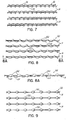
- FIG. 7 schematically illustrates an expanded swirl pattern 110 dispensed onto elastic strands 14 in accordance with the principles of this invention.
- Swirl pattern 110 has crossover points 112 which define and form adhesive masses. Adhesive masses 112 are connected together by thinner filament sections 114.
- Figs. 8 and 8A illustrate a pattern 120 dispensed onto strands 14 in which the respective adhesive masses 122 have conglomerated to form more solid masses.
- Adhesive masses 122 are shown to be coupled by thinner filament sections 124 which may generally have curvatures as shown. It should be understood, however, that the actual patterns in practice will be more irregularly shaped typically than those shown in the figures. The respective adhesive masses may not have uniform shapes as shown. Sufficient adhesive will be deposited around the strands 14, the flat substrate or sheet to enable proper bonding of the substrate (not shown) and strands 14.
- Fig. 8A illustrates pattern 120 in side elevational view. As is apparent from this view, adhesive masses 122 have enveloped elastic strand 14 such that adhesive is positioned above and below strand 14. Thinner filament sections 124 will typically drop below strand 14 when the adhesive is dispensed from above and may also tend to wrap partially around the bottom of strand 14 if they remain unbroken.
- Fig. 9 illustrates an adhesive pattern 130 in which the thinner filament sections between adhesive masses 132 have all broken thereby forming adhesive masses 132 into discrete, separated dots or masses of adhesive.
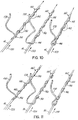
- Figs. 10 and 11 are perspective views showing multiple elastic strands 14 having adhesive filaments 138 dispensed thereon as the strands 14 move in the machine direction of arrows 139.
- Filaments 138 may be dispensed from a multi-orifice nozzle such as nozzle 12 shown and described with respect to Fig. 2.
- filament 138 is discharged in a manner which produces an adhesive pattern 140 having larger adhesive masses 142 separated by thinner filament sections 144.
- some or all of the thinner filament sections 144 may stretch enough to break resulting in an adhesive pattern 140' with discrete, separated adhesive masses 142 as shown in Fig. 11.
- the movement is a crossing pattern in the form of an expanded swirl pattern in the preferred embodiment
- other crossing patterns or non-crossing patterns may be used to achieve the inventive principles.
- a non-crossing vacillating or generally sinusoidal pattern may be used in place of an expanded swirl pattern.
- the width of the pattern transverse to the machine direction must be narrow enough to maintain control of the filament on the elastic strand. That is, the filament pattern should not be so wide as to hang considerably off the elastic strand. In this manner, distinct adhesive masses may be formed rather than a more uniform and excessive coating of the elastic strand.
- the adhesive filament should have a component of movement, such as a swirling or vacillating movement, which is in the machine direction and an alternating component of movement which is opposite to the machine direction.
- the adhesive filament movement in the machine direction causes a momentary build-up of adhesive on the elastic strand to form a distinct adhesive mass on the strand.
- the adhesive filament movement in the opposite direction causes a momentary stretching of the adhesive filament to form the thinner filament sections. If the relative speed differential between the adhesive filament and the elastic strand is great enough during this movement in the opposite direction, then the filament will break between two consecutive adhesive masses.
Landscapes
- Absorbent Articles And Supports Therefor (AREA)
- Application Of Or Painting With Fluid Materials (AREA)
- Chemical Or Physical Treatment Of Fibers (AREA)
- Laminated Bodies (AREA)
- Decoration Of Textiles (AREA)
Abstract
Description
Claims (22)
- A method of applying a continuous filament of adhesive to an elastic strand for securing the elastic strand to a sheet of material comprising:moving the elastic strand and the sheet of material in a converging manner from a first position in which the elastic strand is spaced from the sheet to a second position in which the elastic strand contacts a surface of the sheet,dispensing the continuous filament of adhesive onto the strand in a pattern configured with adhesive masses having a first width and at least some of the adhesive masses coupled by adhesive filament sections having a second width smaller than the first width, andbonding the elastic strand to the sheet of material with at least the adhesive masses.
- The method of claim 1, further comprising:contacting the adhesive masses with the strand when the elastic strand is in the first position.
- The method of claim 1, further comprising:breaking at least some of the thinner filament sections between the adhesive masses to form discrete, separated adhesive masses on the elastic strand.
- The method of claim 1, wherein dispensing the continuous filament of adhesive further comprises:retaining at least some of the thinner filament sections between the adhesive masses, andwrapping at least some of the retained thinner filament sections around the elastic strand before the elastic strand reaches the second position.
- A method of applying a continuous filament of adhesive to an elastic strand for securing the elastic strand to a sheet of material comprising:moving the elastic strand and the sheet in a converging manner from a first position in which the elastic strand is spaced from the sheet to a second position in which the elastic strand contacts a surface of the sheet,dispensing the continuous filament of adhesive toward the strand in a back and forth pattern having crossover points coupled to each other by adhesive filament sections having a first width,contacting at least the crossover points with the strand when the elastic strand is in the first position,forming the crossover points into adhesive masses having a second width greater than the first width, andbonding the elastic strand to the sheet of material with the adhesive masses.
- The method of claim 5, wherein forming the crossover points into adhesive masses further comprises:breaking at least some of the thinner filament sections between the adhesive masses to form discrete, separated adhesive masses on the elastic strand.
- The method of claim 6, wherein forming the crossover points into adhesive masses further comprises:retaining at least some of the thinner filament sections to connect adjacent adhesive masses, andwrapping at least some of the retained thinner filament sections around the elastic strand before the elastic strand reaches the second position.
- The method of claim 5, wherein dispensing the continuous filament of adhesive further comprises:forming the filament into a swirling pattern.
- A method of applying continuous filaments of adhesive to a plurality of spaced apart elastic strands for securing the elastic strands to a sheet of material comprising:moving the elastic strands and the sheet in a converging manner from a first position in which the elastic strands are spaced from the sheet to a second position in which the elastic strands contact a surface of the sheet,dispensing the continuous filaments of adhesive respectively onto corresponding ones of the elastic strands in a pattern configured with adhesive masses having a first width and coupled by adhesive filament sections having a second width smaller than the first width, andbonding the elastic strands to the sheet of material with at least the adhesive masses.
- The method of claim 9, further comprising:contacting at least the adhesive masses of each filament with the corresponding elastic strand when the corresponding elastic strand is in the first position.
- The method of claim 9, further comprising:breaking at least some of the thinner filament sections between the adhesive masses to form discrete, separated adhesive masses on the corresponding elastic strands.
- The method of claim 9, wherein dispensing the continuous filament of adhesive further comprises:retaining at least some of the thinner filament sections between the adhesive masses, andwrapping at least some of the retained thinner filament sections around the corresponding elastic strands before the corresponding elastic strands reach the second position.
- A method of applying continuous filaments of adhesive to a plurality of spaced apart elastic strands for securing the elastic strands to a sheet of material comprising:moving the elastic strands and the sheet in a converging manner from a first position in which the elastic strands are spaced from the sheet to a second position in which the elastic strands contact a surface of the sheet,dispensing the continuous filaments of adhesive respectively toward corresponding ones of the elastic strands in back and forth patterns each having crossover points coupled to each other by adhesive filament sections having a first width,contacting at least the crossover points with the corresponding elastic strand when the corresponding elastic strand is in the first position,forming the crossover points into adhesive masses having a second width greater than the first width, andbonding the elastic strands to the sheet of material with the adhesive masses.
- The method of claim 13, wherein forming the crossover points into adhesive masses further comprises:breaking at least some of the thinner filament sections between the adhesive masses to form discrete, separated adhesive masses on the corresponding elastic strands.
- The method of claim 13, wherein forming the crossover points into adhesive masses further comprises:retaining at least some of the thinner filament sections to connect adjacent adhesive masses, andwrapping at least some of the retained thinner filament sections around the corresponding elastic strands before the elastic strands reach the second position.
- The method of claim 13, wherein dispensing the continuous filaments of adhesive further comprises:forming each filament into a swirling pattern.
- A method of applying a continuous filament of adhesive to an elastic strand for securing the elastic strand to a sheet of material comprising:moving the elastic strand and the sheet in a converging manner from a first position in which the elastic strand is spaced from the sheet to a second position in which the elastic strand contacts a surface of the sheet,dispensing the continuous filament of adhesive onto the strand in the first position and in a pattern configured with adhesive masses having a first width and coupled by adhesive filament sections having a second width smaller than the first width,breaking the adhesive filament sections between adjacent adhesive masses to separate the adjacent adhesive masses from each other, andbonding the elastic strand to the sheet of material with the adhesive masses.
- A method of applying continuous filaments of adhesive to a plurality of spaced apart elastic strands for securing the elastic strands to a sheet of material comprising:moving the elastic strands and the sheet in a converging manner from a first position in which the elastic strands are spaced from the sheet to a second position in which the elastic strands contact a surface of the sheet,dispensing the continuous filaments of adhesive respectively onto corresponding ones of the elastic strands in the first position and in a pattern configured with adhesive masses having a first width and coupled by adhesive filament sections having a second width smaller than the first width,breaking the adhesive filament sections between adjacent adhesive masses to separate the adjacent filament masses from each other, andbonding the elastic strands to the sheet of material with the adhesive masses.
- An article comprising:a first flat substrate, andan elastic strand secured on said first flat substrate by a plurality of adhesive masses extending along and contacting said elastic strand and said first flat substrate, at least some of said adhesive masses being coupled together by thinner adhesive filament sections.
- The article of claim 19, further comprising a second flat substrate, said first and second flat substrates adhered to opposite sides of said elastic strand by said adhesive masses.
- The article of claim 19, further comprising:a plurality of elastic strands secured on said first flat substrate by a plurality of adhesive masses respectively extending along said elastic strands, at least some of said adhesive masses along each of said elastic strands being coupled together by thinner filament sections.
- The article of claim 21, further comprising a second flat substrate, said first and second flat substrates adhered to opposite sides of said elastic strands by said adhesive masses.
Applications Claiming Priority (4)
| Application Number | Priority Date | Filing Date | Title |
|---|---|---|---|
| US282708 | 1988-12-12 | ||
| US36461302P | 2002-03-15 | 2002-03-15 | |
| US364613P | 2002-03-15 | ||
| US10/282,708 US6936125B2 (en) | 2002-03-15 | 2002-10-29 | Method of applying a continuous adhesive filament to an elastic strand with discrete bond points and articles manufactured by the method |
Publications (3)
| Publication Number | Publication Date |
|---|---|
| EP1344574A2 true EP1344574A2 (en) | 2003-09-17 |
| EP1344574A3 EP1344574A3 (en) | 2007-03-21 |
| EP1344574B1 EP1344574B1 (en) | 2010-08-11 |
Family
ID=27767516
Family Applications (1)
| Application Number | Title | Priority Date | Filing Date |
|---|---|---|---|
| EP20030004420 Expired - Lifetime EP1344574B1 (en) | 2002-03-15 | 2003-02-27 | Method of applying a continuous adhesive filament to an elastic strand with discrete bond points |
Country Status (4)
| Country | Link |
|---|---|
| US (2) | US6936125B2 (en) |
| EP (1) | EP1344574B1 (en) |
| JP (1) | JP4549633B2 (en) |
| DE (1) | DE60333694D1 (en) |
Cited By (3)
| Publication number | Priority date | Publication date | Assignee | Title |
|---|---|---|---|---|
| EP1579834A4 (en) * | 2002-12-20 | 2007-05-02 | Uni Charm Corp | Disposable wearing article |
| EP1916038A3 (en) * | 2006-10-27 | 2008-08-06 | Nordson Corporation | Applicator apparatus for the application of liquid materials |
| EP2301503A1 (en) * | 2009-09-25 | 2011-03-30 | Livedo Corporation | Sheet member and method of manufacturing sheet member |
Families Citing this family (30)
| Publication number | Priority date | Publication date | Assignee | Title |
|---|---|---|---|---|
| US20050013975A1 (en) * | 2003-07-14 | 2005-01-20 | Nordson Corporation | Method of securing elastic strands to flat substrates and products produced by the method |
| US20030173024A1 (en) * | 2002-03-15 | 2003-09-18 | Nordson Corporation | Method of securing elastic strands to flat substrates and products produced by the method |
| US6911232B2 (en) * | 2002-04-12 | 2005-06-28 | Nordson Corporation | Module, nozzle and method for dispensing controlled patterns of liquid material |
| CN1658809A (en) * | 2002-08-29 | 2005-08-24 | 贝亲株式会社 | absorbent product |
| US7578882B2 (en) * | 2003-01-22 | 2009-08-25 | Nordson Corporation | Module, nozzle and method for dispensing controlled patterns of liquid material |
| US20050137549A1 (en) * | 2003-12-22 | 2005-06-23 | Kimberly-Clark Worldwide, Inc. | Use of swirl-like adhesive patterns in the formation of absorbent articles |
| JP2006130042A (en) * | 2004-11-05 | 2006-05-25 | Livedo Corporation | Disposable absorbent article and method for producing the same |
| ES1060479Y (en) * | 2005-06-10 | 2006-01-01 | Melton S L | PERFECTED VISCOSE PRODUCT APPLICATOR. |
| US20080114322A1 (en) * | 2006-11-10 | 2008-05-15 | Kimberly-Clark Worldwide, Inc. | Body panel for an adjustable pant-like disposable undergarment and the undergarment itself |
| US7798434B2 (en) * | 2006-12-13 | 2010-09-21 | Nordson Corporation | Multi-plate nozzle and method for dispensing random pattern of adhesive filaments |
| US8074902B2 (en) | 2008-04-14 | 2011-12-13 | Nordson Corporation | Nozzle and method for dispensing random pattern of adhesive filaments |
| US8445061B2 (en) * | 2009-07-17 | 2013-05-21 | Illinois Tool Works Inc. | Metering system for hot melt adhesives with variable adhesive volumes |
| US8551562B2 (en) | 2009-07-17 | 2013-10-08 | Illnois Tool Works Inc. | Method for metering hot melt adhesives with variable adhesive volumes |
| US9718081B2 (en) * | 2009-08-31 | 2017-08-01 | Illinois Tool Works Inc. | Metering system for simultaneously dispensing two different adhesives from a single metering device or applicator onto a common substrate |
| US9573159B2 (en) * | 2009-08-31 | 2017-02-21 | Illinois Tool Works, Inc. | Metering system for simultaneously dispensing two different adhesives from a single metering device or applicator onto a common substrate |
| US9119387B2 (en) * | 2010-03-12 | 2015-09-01 | Metamatrix, Llc. | Pest control trap |
| ES2604185T3 (en) | 2011-04-11 | 2017-03-03 | Nordson Corporation | System, nozzle and procedure for coating elastic strands |
| US20130240122A1 (en) * | 2012-03-13 | 2013-09-19 | Nordson Corporation | Method of manufacturing a personal hygiene product |
| USD671970S1 (en) | 2012-04-10 | 2012-12-04 | Nordson Corporation | Nozzle for applying adhesive to strands |
| US9034425B2 (en) | 2012-04-11 | 2015-05-19 | Nordson Corporation | Method and apparatus for applying adhesive on an elastic strand in a personal disposable hygiene product |
| US9682392B2 (en) | 2012-04-11 | 2017-06-20 | Nordson Corporation | Method for applying varying amounts or types of adhesive on an elastic strand |
| US9914144B2 (en) | 2012-04-16 | 2018-03-13 | Nordson Corporation | Color coded nozzle adapter and locator tool |
| KR102070473B1 (en) * | 2012-05-09 | 2020-01-29 | 유니챰 가부시키가이샤 | Composite stretchable material |
| JP5836881B2 (en) * | 2012-05-09 | 2015-12-24 | ユニ・チャーム株式会社 | Composite stretch material |
| JP5836880B2 (en) * | 2012-05-09 | 2015-12-24 | ユニ・チャーム株式会社 | Composite stretch material |
| USD673594S1 (en) | 2012-06-18 | 2013-01-01 | Nordson Corporation | Nozzle for applying adhesive to strands |
| US9724719B2 (en) | 2012-11-09 | 2017-08-08 | L&P Property Management Company | Self-cleaning spray valve assembly |
| US9566599B2 (en) * | 2012-11-09 | 2017-02-14 | L&P Property Management Company | Self-cleaning spray valve assembly |
| US10973699B2 (en) | 2016-12-20 | 2021-04-13 | The Procter & Gamble Company | Methods and apparatuses for making elastomeric laminates with elastic strands unwound from beams |
| EP3675785B1 (en) | 2017-09-01 | 2021-11-10 | The Procter & Gamble Company | Methods and apparatuses for making elastomeric laminates |
Family Cites Families (32)
| Publication number | Priority date | Publication date | Assignee | Title |
|---|---|---|---|---|
| CA1025291A (en) * | 1973-11-19 | 1978-01-31 | Busm Co. Limited | Adhesive process and apparatus |
| US4185981A (en) * | 1975-08-20 | 1980-01-29 | Nippon Sheet Glass Co.,Ltd. | Method for producing fibers from heat-softening materials |
| JPS5857374B2 (en) * | 1975-08-20 | 1983-12-20 | 日本板硝子株式会社 | Fiber manufacturing method |
| JPS6075602A (en) * | 1983-09-30 | 1985-04-30 | ノ−ドソン株式会社 | Disposable diaper and its production |
| DE3740410A1 (en) * | 1987-11-28 | 1989-06-08 | Fuller H B Gmbh | Method of permanently joining stretchable elements in filament or ribbon form on a sheet-like substrate and use of the same for producing ruffled film web sections |
| US5171512A (en) * | 1988-03-25 | 1992-12-15 | Mitsui Petrochemical Industries, Ltd. | Melt-blowing method having notches on the capillary tips |
| US4949668A (en) * | 1988-06-16 | 1990-08-21 | Kimberly-Clark Corporation | Apparatus for sprayed adhesive diaper construction |
| US4844003A (en) * | 1988-06-30 | 1989-07-04 | Slautterback Corporation | Hot-melt applicator |
| US4957783A (en) * | 1988-10-05 | 1990-09-18 | Nordson Corporation | Method and apparatus for dispensing droplets of molten thermoplastic adhesive |
| JPH02289165A (en) * | 1988-12-07 | 1990-11-29 | Nordson Corp | Apparatus for applying adhesive to elastic string |
| JPH0611275B2 (en) * | 1989-06-29 | 1994-02-16 | ユニ・チャーム株式会社 | Disposable brief manufacturing method |
| US5030303A (en) * | 1989-07-28 | 1991-07-09 | Nordson Corporation | Method for forming disposable garments with a waste containment pocket |
| JP2916784B2 (en) * | 1989-11-01 | 1999-07-05 | ノードソン株式会社 | Hot melt adhesive application method and apparatus |
| US5065943A (en) * | 1990-09-06 | 1991-11-19 | Nordson Corporation | Nozzle cap for an adhesive dispenser |
| US5208064A (en) * | 1991-11-04 | 1993-05-04 | Nordson Corporation | Method and apparatus for optically monitoring and controlling a moving fiber of material |
| US5267693A (en) * | 1992-02-12 | 1993-12-07 | Dickey Barry A | Spray gun non-stick paint connector block |
| US5785258A (en) * | 1993-10-08 | 1998-07-28 | Vortexx Group Incorporated | Method and apparatus for conditioning fluid flow |
| US5525175A (en) * | 1994-05-27 | 1996-06-11 | Kimberly-Clark Corporation | Apparatus and method for applying a curved elastic to a moving web |
| DE9420324U1 (en) * | 1994-12-20 | 1995-02-09 | Chiron-Werke Gmbh & Co Kg, 78532 Tuttlingen | Air head |
| US5553758A (en) * | 1995-01-27 | 1996-09-10 | Melendy; Peter S. | Nozzle adaptor for applying hot melt adhesive |
| US6527369B1 (en) | 1995-10-25 | 2003-03-04 | Hewlett-Packard Company | Asymmetric printhead orifice |
| US5902540A (en) * | 1996-10-08 | 1999-05-11 | Illinois Tool Works Inc. | Meltblowing method and apparatus |
| US5904298A (en) * | 1996-10-08 | 1999-05-18 | Illinois Tool Works Inc. | Meltblowing method and system |
| US5882573A (en) * | 1997-09-29 | 1999-03-16 | Illinois Tool Works Inc. | Adhesive dispensing nozzles for producing partial spray patterns and method therefor |
| JPH11244774A (en) | 1998-02-28 | 1999-09-14 | San Tool:Kk | Spiral application method of adhesive |
| JPH11319674A (en) * | 1998-05-17 | 1999-11-24 | San Tool:Kk | Nozzle device and gun unit for adhesive spiral spray coating apparatus |
| JP3816676B2 (en) * | 1998-09-04 | 2006-08-30 | 株式会社クラレ | Sheet-like elastic composite and method for producing the same |
| US6250357B1 (en) * | 1999-03-15 | 2001-06-26 | William P. Niedermeyer | Method and apparatus for briefs with pad support panel |
| JP4474620B2 (en) | 2000-03-14 | 2010-06-09 | ノードソン株式会社 | Apparatus and method for applying adhesive to thread-like or string-like object |
| US6361634B1 (en) * | 2000-04-05 | 2002-03-26 | Kimberly-Clark Worldwide, Inc. | Multiple stage coating of elastic strands with adhesive |
| US20020119722A1 (en) * | 2000-05-15 | 2002-08-29 | Welch Howard M. | Elastic stranded laminate with adhesive bonds and method of manufacture |
| US20020007148A1 (en) * | 2000-05-15 | 2002-01-17 | May Raymond Jeffrey | Garment having integrated zone of elastic tension aligned with an opening |
-
2002
- 2002-10-29 US US10/282,708 patent/US6936125B2/en not_active Expired - Lifetime
-
2003
- 2003-02-27 EP EP20030004420 patent/EP1344574B1/en not_active Expired - Lifetime
- 2003-02-27 DE DE60333694T patent/DE60333694D1/en not_active Expired - Lifetime
- 2003-03-14 JP JP2003070783A patent/JP4549633B2/en not_active Expired - Fee Related
-
2005
- 2005-05-16 US US11/130,284 patent/US7014911B2/en not_active Expired - Lifetime
Cited By (9)
| Publication number | Priority date | Publication date | Assignee | Title |
|---|---|---|---|---|
| EP1579834A4 (en) * | 2002-12-20 | 2007-05-02 | Uni Charm Corp | Disposable wearing article |
| EP1916038A3 (en) * | 2006-10-27 | 2008-08-06 | Nordson Corporation | Applicator apparatus for the application of liquid materials |
| US7699243B2 (en) | 2006-10-27 | 2010-04-20 | Nordson Corporation | Applicator device for applying liquid material |
| EP2289633A3 (en) * | 2006-10-27 | 2011-12-21 | Nordson Corporation | Applicator apparatus for the application of liquid material |
| EP2301503A1 (en) * | 2009-09-25 | 2011-03-30 | Livedo Corporation | Sheet member and method of manufacturing sheet member |
| CN102028584A (en) * | 2009-09-25 | 2011-04-27 | 利卫多株式会社 | Sheet member and method of manufacturing sheet member |
| CN102028584B (en) * | 2009-09-25 | 2013-08-07 | 利卫多株式会社 | Sheet member and method of manufacturing sheet member |
| US8568552B2 (en) | 2009-09-25 | 2013-10-29 | Livedo Corporation | Sheet member and method of manufacturing sheet member |
| US8709581B2 (en) | 2009-09-25 | 2014-04-29 | Livedo Corporation | Sheet member and method of manufacturing sheet member |
Also Published As
| Publication number | Publication date |
|---|---|
| EP1344574B1 (en) | 2010-08-11 |
| US7014911B2 (en) | 2006-03-21 |
| US20050208277A1 (en) | 2005-09-22 |
| EP1344574A3 (en) | 2007-03-21 |
| US20030173018A1 (en) | 2003-09-18 |
| JP2003328275A (en) | 2003-11-19 |
| DE60333694D1 (en) | 2010-09-23 |
| US6936125B2 (en) | 2005-08-30 |
| JP4549633B2 (en) | 2010-09-22 |
Similar Documents
| Publication | Publication Date | Title |
|---|---|---|
| US6936125B2 (en) | Method of applying a continuous adhesive filament to an elastic strand with discrete bond points and articles manufactured by the method | |
| US10807114B2 (en) | System, nozzle and method for coating elastic strands | |
| CA2279282C (en) | Omega spray pattern and method therefor | |
| US20050013975A1 (en) | Method of securing elastic strands to flat substrates and products produced by the method | |
| US7950346B2 (en) | Module, nozzle and method for dispensing controlled patterns of liquid material | |
| US9682392B2 (en) | Method for applying varying amounts or types of adhesive on an elastic strand | |
| US20010022155A1 (en) | Device and method for applying adhesive to materials such as strands | |
| EP1344510A1 (en) | Method of securing elastic strands to flat substrates and products produced by the method | |
| US7175108B2 (en) | Applicator and nozzle for dispensing controlled patterns of liquid material | |
| EP3210675A1 (en) | Method, apparatus, and nozzle for applying varying amounts or types of adhesive on an elastic strand | |
| MXPA04006851A (en) | Strand orientation alignment in strand coating systems and methods. | |
| HK1081898B (en) | Module, nozzle and method for dispensing controlled patterns of liquid material |
Legal Events
| Date | Code | Title | Description |
|---|---|---|---|
| PUAI | Public reference made under article 153(3) epc to a published international application that has entered the european phase |
Free format text: ORIGINAL CODE: 0009012 |
|
| AK | Designated contracting states |
Kind code of ref document: A2 Designated state(s): AT BE BG CH CY CZ DE DK EE ES FI FR GB GR HU IE IT LI LU MC NL PT SE SI SK TR |
|
| AX | Request for extension of the european patent |
Extension state: AL LT LV MK RO |
|
| PUAL | Search report despatched |
Free format text: ORIGINAL CODE: 0009013 |
|
| AK | Designated contracting states |
Kind code of ref document: A3 Designated state(s): AT BE BG CH CY CZ DE DK EE ES FI FR GB GR HU IE IT LI LU MC NL PT SE SI SK TR |
|
| AX | Request for extension of the european patent |
Extension state: AL LT LV MK RO |
|
| 17P | Request for examination filed |
Effective date: 20070921 |
|
| 17Q | First examination report despatched |
Effective date: 20071024 |
|
| AKX | Designation fees paid |
Designated state(s): DE SE |
|
| GRAP | Despatch of communication of intention to grant a patent |
Free format text: ORIGINAL CODE: EPIDOSNIGR1 |
|
| GRAC | Information related to communication of intention to grant a patent modified |
Free format text: ORIGINAL CODE: EPIDOSCIGR1 |
|
| RTI1 | Title (correction) |
Free format text: METHOD OF APPLYING A CONTINUOUS ADHESIVE FILAMENT TO AN ELASTIC STRAND WITH DISCRETE BOND POINTS |
|
| RBV | Designated contracting states (corrected) |
Designated state(s): DE GB |
|
| GRAS | Grant fee paid |
Free format text: ORIGINAL CODE: EPIDOSNIGR3 |
|
| GRAA | (expected) grant |
Free format text: ORIGINAL CODE: 0009210 |
|
| AK | Designated contracting states |
Kind code of ref document: B1 Designated state(s): DE GB |
|
| REG | Reference to a national code |
Ref country code: GB Ref legal event code: FG4D |
|
| REF | Corresponds to: |
Ref document number: 60333694 Country of ref document: DE Date of ref document: 20100923 Kind code of ref document: P |
|
| PLBE | No opposition filed within time limit |
Free format text: ORIGINAL CODE: 0009261 |
|
| STAA | Information on the status of an ep patent application or granted ep patent |
Free format text: STATUS: NO OPPOSITION FILED WITHIN TIME LIMIT |
|
| 26N | No opposition filed |
Effective date: 20110512 |
|
| REG | Reference to a national code |
Ref country code: DE Ref legal event code: R097 Ref document number: 60333694 Country of ref document: DE Effective date: 20110512 |
|
| PGFP | Annual fee paid to national office [announced via postgrant information from national office to epo] |
Ref country code: GB Payment date: 20150218 Year of fee payment: 13 |
|
| GBPC | Gb: european patent ceased through non-payment of renewal fee |
Effective date: 20160227 |
|
| PG25 | Lapsed in a contracting state [announced via postgrant information from national office to epo] |
Ref country code: GB Free format text: LAPSE BECAUSE OF NON-PAYMENT OF DUE FEES Effective date: 20160227 |
|
| PGFP | Annual fee paid to national office [announced via postgrant information from national office to epo] |
Ref country code: DE Payment date: 20190219 Year of fee payment: 17 |
|
| REG | Reference to a national code |
Ref country code: DE Ref legal event code: R119 Ref document number: 60333694 Country of ref document: DE |
|
| PG25 | Lapsed in a contracting state [announced via postgrant information from national office to epo] |
Ref country code: DE Free format text: LAPSE BECAUSE OF NON-PAYMENT OF DUE FEES Effective date: 20200901 |