Field of the Invention
-
The present invention relates to a protector and an
indwelling needle assembly. More specifically, the
invention relates to a protector for a needle body that is
used, for example, by being punctured into a blood vessel
etc during infusion or blood collection, and to an
indwelling needle assembly provided with the protector.
Description of Prior Art
-
When performing an infusion to a patient, an
indwelling needle to be connected with an infusion line is
punctured into a blood vessel of the patient to be
indwelled therein. Such an indwelling needle consists of a
hollow outer needle, an outer needle hub secured to the
base end of the outer needle, an inner needle inserted into
the outer needle and having a sharp needle tip at its tip
end, and an inner needle hub secured to the base end of the
inner needle.
-
When puncturing the indwelling needle into the blood
vessel of the patient, the inner needle is inserted into
the outer needle and then the puncturing operation is
performed in a state where the needle tip of the inner
needle is being projected through the tip end of the outer
needle. Then, when the needle tip of the inner needle
reaches the interior of the blood vessel, blood flowing in
through an opening at the needle tip passes through the
inner hole of the inner needle to flow into the interior of
the inner needle hub that is transparent (flashback).
Thus, it can be confirmed that the inner needle has secured
the blood vessel.
-
Upon confirming this flashback, the inner needle and
the outer needle are advanced slightly to insert the tip
end of the outer needle into the blood vessel. Next, while
grasping the outer needle with a hand, the inner needle is
drawn out from the outer needle and the connector of the
infusion line is connected to the outer needle hub. Then,
the administration of infusion is performed via the
connected infusion line and the outer needle.
-
In this case, the inner needle drawn out from the
outer needle becomes unnecessary, so that it is discarded
for disposal. However, if it is disposed of as it is,
there is a fear that a finger etc of a person performing
the disposal or the like is accidentally stuck with the
needle tip of the inner needle. In particular, since blood
is adhered to or remains on the surface of the inner needle
or its interior, such accidental needle sticks could become
the cause of infection.
-
Accordingly, it is preferred that a used inner needle
be accommodated into a hard, sturdy dedicated container for
disposal so as to prevent accidental sticking of the needle
tip. However, from the viewpoint of efficiency of
operations, it is difficult to carry such a dedicated
container at all times and bring it to each patient.
Therefore, under the present circumstances, such measures
are taken as to dispose of a used inner needle by putting
it into an unsealed packing material that previously
accommodated the indwelling needle kit, or discard it by
covering a cap over its needle tip.
-
However, when performing such an operation of packing
the inner needle in a packing material or covering it with
the cap, too, utmost caution needs to be exercised so that
a hand of the operator is not accidentally stuck with the
needle tip of the inner needle, thus causing a problem in
that a great deal of time and trouble is required for the
disposal of a used inner needle.
-
An object of the present invention is to provide a
protector capable of accommodating the needle tip of a used
needle body by a simple operation to ensure a high level of
safety during needle disposal or the like, and to provide
an indwelling needle assembly provided with the protector.
Summary of the Invention
-
The above object can be attained by the present
invention as described in (1) to (25) below.
- (1) A protector displaceable between a first attitude
in which the protector can move relatively along a
longitudinal direction of a needle body having a sharp
needle tip at its tip end and a second attitude in which
the relative movement of the protector along the
longitudinal direction of the needle body is prohibited in
a state where the protector covers the needle tip of the
needle body,
- the protector having a plate-like brake portion
having formed therein a hole through which the needle body
can penetrate, characterized in that,
- in the second attitude, an inclination angle of the
brake portion relative to the needle body becomes smaller
than the inclination angle in the first attitude, so that a
frictional force is generated or increased between an inner
surface of the hole of the brake portion and an outer
peripheral surface of the needle body to thereby prohibit
the relative movement of the protector along the
longitudinal direction of the needle body.
- (2) The protector according to (1) described above,
having:
- urging means for urging the brake portion so that the
inclination angle of the brake portion relative to the
needle body becomes smaller; and
- inclination regulating means for regulating an
inclination of the brake portion relative to the needle
body in the first attitude,
- in which the regulation of the inclination effected
by the inclination regulating means is released upon
movement of the protector to a tip end portion of the
needle body to thereby bring the protector into the second
attitude from the first attitude.
- (3) A protector displaceable between a first attitude
in which the protector can move relatively along a
longitudinal direction of a needle body having a sharp
needle tip at its tip end and a second attitude in which
the relative movement of the protector along the
longitudinal direction of the needle body is prohibited in
a state where the protector covers the needle tip of the
needle body,
- the protector having a main body portion formed by
deforming a plate-like member having an elasticity,
characterized in that:
- a first hole and a second hole through which the
needle body can penetrate are formed in the main body
portion;
- a penetration portion through which the needle body
can penetrate is formed on the needle tip side of the main
body portion;
- in the first attitude, the needle body penetrates
through the first hole, the second hole, and the
penetration portion, and by moving the protector in a tip
end direction relative to the needle body from that state
to release an engagement between the penetration portion
and the needle body, the protector is elastically deformed
into the second attitude such that an inclination angle of
the plate-like member near the first hole relative to the
needle body becomes smaller than the inclination angle in
the first attitude, so that a frictional force is generated
or increased between an inner surface of the first hole and
an outer peripheral surface of the needle body to thereby
prohibit the relative movement of the protector along the
longitudinal direction of the needle body.
- (4) The protector according to (3) described above,
in which the tip end portion of the main body portion
covers the needle tip of the needle body in the second
attitude.
- (5) The protector according to (3) or (4) described
above, in which the main body portion has a substantially S
shape as a whole, the first hole is formed in the center of
the main body portion, and the second hole is formed on the
needle root side of the main body portion.
- (6) The protector according to any one of (3) through
(5) described above, having a lateral displacement
preventing member which is located between the penetration
portion and the first hole and prevents lateral
displacement of the needle tip of the needle body in the
second attitude.
- (7) The protector according to any one of (3) through
(6) described above, having a cap member which is located
between the penetration portion and the first hole and
covers the needle tip of the needle body in the second
attitude.
- (8) The protector according to any one of (1) through
(7) described above, having means for exerting such a force
on the brake portion or the plate-like member near the
first hole as to make the inclination angle thereof become
smaller upon pressing the tip end portion of the protector
in a base end direction in the second attitude.
- (9) The protector according to any one of (1) through
(8) described above, in which, in the first attitude, the
inclination angle of the brake portion or the plate-like
member near the first hole relative to the needle body is
substantially a right angle.
- (10) The protector according to any one of (1)
through (9) described above, in which an inner diameter of
the first hole (the hole) is 0.01 to 1 mm larger than an
outer diameter of the needle body.
- (11) The protector according to any one of (1)
through (10) described above, in which a thickness of the
brake portion or the plate-like member is 0.05 to 2 mm.
- (12) A protector displaceable between a first
attitude in which the protector can move relatively along a
longitudinal direction of a needle body having a sharp
needle tip at its tip end and a second attitude in which
the relative movement of the protector along the
longitudinal direction of the needle body is prohibited in
a state where the protector covers the needle tip of the
needle body, the protector including:
- a plate-like brake portion constructed of a metallic
material and having formed therein a hole through which the
needle body can penetrate;
- urging means for urging the brake portion so as to
make an inclination angle of the brake portion relative to
the needle body become smaller; and
- needle-body abutting portion constructed of a resin
material, which is provided further on the needle tip side
than the brake portion and has a function of abutting with
the needle body in the first attitude to prevent the
inclination angle of the brake portion relative to the
needle body from changing,
characterized in that, when the protector is moved in
a tip end direction from the first attitude relative to the
needle body and the needle-body abutting portion passes the
needle tip to be separated apart from the needle body, the
protector is deformed into the second attitude such that
the inclination angle of the brake portion relative to the
needle body becomes smaller than the inclination angle in
the first attitude due to the urging means, so that a
frictional force is generated or increased between an inner
surface of the hole and a surface of the needle body to
thereby prohibit the relative movement of the protector
along the longitudinal direction of the needle body. - (13) The protector according to (12) described above,
in which the urging means is a plate-like member extending
continuously from the brake portion and exerts an urging
force due to its elasticity.
- (14) The protector according to (12) or (13)
described above, in which, in the first attitude, a sliding
resistance of the needle-body abutting portion with respect
to the needle body is smaller than a sliding resistance of
the brake portion with respect to the needle body.
- (15) The protector according to any one of (12)
through (14) described above, having a needle-tip receiving
portion that covers the needle tip from the tip end side.
- (16) The protector according to any one of (12)
through (15) described above, having a cover portion that
covers at least an area near the needle-body abutting
portion, the cover portion having a function of hindering
an operation of moving the area near the needle-body
abutting portion in a tip end direction in the second
attitude.
- (17) The protector according to any one of (12)
through (16) described above, in which a second hole
through which the needle body can penetrate is formed
further on the needle root side than the brake portion.
- (18) The protector according to (17) described above,
having a cover portion which is provided continuously from
a member near the second hole and covers at least the area
near the needle-body abutting portion,
in which, when an external force acting in a base end
direction and/or a tip end direction is imparted to the
cover portion in the second attitude, such a force as to
make an inclination angle of the member near the second
hole relative to the needle body become smaller is exerted
on the member near the second hole. - (19) The protector according to any one of (12)
through (18) described above, in which the protector covers
the needle tip of the needle body substantially from all
around in the second attitude.
- (20) An indwelling needle assembly characterized by
including:
- an inner needle having a sharp needle tip at its tip
end;
- the protector according to any one of (1) through
(19) described above which is fitted to the inner needle;
- an inner needle hub installed on the base end side of
the inner needle;
- a hollow outer needle into which the inner needle can
be inserted; and
- an outer needle hub installed on the base end side of
the outer needle.
- (21) The indwelling needle assembly according to (20)
described above, having connecting means for connecting the
outer needle hub and the protector with each other.
- (22) The indwelling needle assembly according to (21)
described above, in which:
- when the inner needle hub is moved in a base end
direction relative to the outer needle hub, a connected
state between the protector and the outer needle with hub
is maintained by the connecting means until the protector
is displaced from the first attitude into the second
attitude by being moved in a tip end direction relative to
the inner needle; and
- the protector and the outer needle hub can be
separated from each other after the protector is displaced
into the second attitude.
- (23) The indwelling needle assembly according to (21)
or (22) described above, in which the connecting means has
a rupturing portion that ruptures upon the separation of
the protector and the outer needle hub from each other.
- (24) The indwelling needle assembly according to any
one of (21) through (23) described above, in which the
connecting means has an abutting member that abuts with the
protector from the base end side.
-
-
According to the present invention, there can be
provided a protector and an indwelling needle assembly
which ensure an excellent level of hygiene and safety by
allowing a used needle body to be swiftly and safely
covered with the protector by a simple operation and
eliminating accidental sticking of the needle tip into a
hand, finger, etc during needle disposal or the like.
-
Further, according to the present invention, the
above-mentioned effect can be realized using an extremely
small protector, and during its use, the protector can be
accommodated in a slight space provided in the needle root
portion. Therefore, it is easy to secure the installation
space for the protector, so that the protector can be used
by being fitted to an ordinary needle body that does not
have a special structure.
-
Further, the protector of the present invention,
which has the needle-body abutting portion constructed of a
resin material, can be moved relative to the needle body
smoothly (with a relatively small operational force) in the
first attitude. Thus, the operation of covering the needle
tip with the protector can be performed in a swift, easy,
and reliable manner.
-
Further, if the main body portion of the protector is
formed by deforming the plate-like member, the above-mentioned
effect can be attained by using an extremely
simple structure.
-
Further, if the lateral displacement preventing
member is provided, it is possible to more reliably prevent
the needle tip from projecting even if a strong, external
force in a lateral direction is exerted on the protector.
-
Further, according to the indwelling needle assembly
of the present invention, it is unnecessary to perform
machining (such as forming a concave portion or a convex
portion) on the inner needle (needle body) to prevent
dislodging of the protector therefrom. As a result, the
tip end portion of the inner needle can be formed to have a
smooth outer peripheral surface, thereby facilitating
manufacture while not causing a reduction in the strength
of the inner needle or an increase in insertion resistance.
-
Further, if the connecting means is provided in the
indwelling needle assembly of the present invention, the
needle tip of the inner needle can be covered with the
protector more reliably by a simpler operation, thus
achieving a further improvement in safety and operability.
Brief Description of the Drawings
-
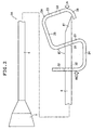
- Fig. 1 is a side view (use state) showing a
puncturing instrument (injection needle) having a protector
according to a first embodiment of the present invention.
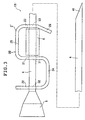
- Fig. 2 is a side view (needle-tip accommodating
state) showing the puncturing instrument (injection needle)
having the protector according to the first embodiment of
the present invention.
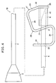
- Fig. 3 is a side view (use state) showing a
puncturing instrument (injection needle) having a protector
according to a second embodiment of the present invention.
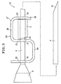
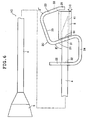
- Fig. 4 is a side view (needle-tip accommodating
state) showing the puncturing instrument (injection needle)
having the protector according to the second embodiment of
the present invention.
- Fig. 5 is a side view (use state) showing a
puncturing instrument (injection needle) having a protector
according to a third embodiment of the present invention.
- Fig. 6 is a side view (needle-tip accommodating
state) showing the puncturing instrument (injection needle)
having the protector according to the third embodiment of
the present invention.
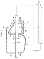
- Fig. 7 is a cross-sectional side view showing a state
where a protector according to a fourth embodiment of the
present invention is fitted to a needle body, in which the
protector is shown as being in a first attitude.
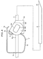
- Fig. 8 is a side view showing a state where the
protector according to the fourth embodiment of the present
invention is fitted to the needle body, in which the
protector is shown as being in the first attitude.
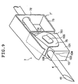
- Fig. 9 is a perspective view showing a state where
the protector according to the fourth embodiment of the
present invention is fitted to the needle body, in which
the protector is shown as being in the first attitude.
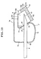
- Fig. 10 is a cross-sectional side view in which the
protector shown in Fig. 7 is shown as being in a second
attitude.
- Fig. 11 is a cross-sectional side view showing a
state where a protector according to a fifth embodiment of
the present invention is fitted to the needle body, in
which the protector is shown as being in the second
attitude.
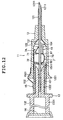
- Fig. 12 is a longitudinal sectional view showing an
embodiment of an indwelling needle assembly (assembled
state) of the present invention.
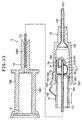
- Fig. 13 is a longitudinal sectional view showing a
state where an inner needle hub is moved relative to an
outer needle hub in the base end direction in the
indwelling needle assembly shown in Fig. 12.
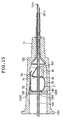
- Fig. 14 is a longitudinal sectional view of an
embodiment of an indwelling assembly of the present
invention, showing another construction example of the
protector.
- Fig. 15 is a longitudinal sectional view of the
vicinity of the outer needle hub in the assembled state,
showing another construction example of connecting means.
-
Description of the Preferred Embodiment Modes
-
Hereinbelow, a protector of the present invention
will be described in detail based on preferred embodiment
modes thereof shown in the accompanying drawings.
[First embodiment of protector]
-
Figs. 1 and 2 are each a side view showing a
protector according to a first embodiment of the present
invention. Note that, in the following description, the
needle tip side as seen in Figs. 1 and 2 is referred to as
a "tip end", whereas the hub side is referred to as a "base
end". Also, with the tip end being pointed up, the left-hand
side is referred to as "one end", whereas the right-hand
side is referred to as "the other end".
-
A puncturing instrument 1A shown in Figs. 1 and 2 is
provided with a needle tube (needle body) 4 having a sharp
needle tip 41 at its tip end, a protector 2A which is
mounted to the needle tube 4 and is capable of
accommodating the needle tip 41 of the needle tube 4, and a
hub 5 fixed to the base end of the needle tube 4.
Hereinbelow, a description will be given of the
constructions of the respective portions.
-
The needle tube 4 is a hollow needle, which is
constructed of, for example, a metallic material such as
stainless steel, aluminum or aluminum alloy, or titan or
titan alloy. The sharp needle tip 41 is formed at the tip
end portion of the needle tube 4. The shape of the needle
tip 41 is not particularly limited; in the present
embodiment, the needle tip 41 is shaped so as to have an
edge surface that is inclined at a predetermined angle
relative to the longitudinal axis of the needle tube 4.
-
The hub 5 is secured (fixed) in a liquid-tight manner
to the base end of the needle tube 4, so that the inner
hole of the needle tube 4 communicates with the inner
portion of the hub 5.
-
Examples of the method for securing the needle tube 4
to the hub 5 include caulking, fusing (thermal fusing,
high-frequency fusing etc), and adhesion using an adhesive.
-
The hub 5 consists of a substantially tubular member,
and is preferably constructed of a transparent (uncolored
transparent), colored transparent, or semi-transparent
resin to ensure the visibility of its inner portion.
-
The hub 5 has a tapered shape such that its outer and
inner diameters gradually increase toward the base end
thereof. Into the thus tapered portion, for example, the
tip end portion of a syringe (not shown) is inserted,
thereby fitting the puncturing instrument 1A to the
syringe.
-
The constituent material for the hub 5 is not
particularly limited, and examples thereof may include
polyolefins such as polyethylene, polypropylene,
polybutadiene, and an ethylene/vinyl acetate copolymer,
polyvinyl chloride, polyurethane, polystyrene, polymethyl
methacrylate, polycarbonate, polyamide, polyesters such as
polyethylene terephthalate, and polybutylene terephthalate,
and various types of resin materials such as acrylic
resins, ABS resin, AS resin, ionomer, polyacetal,
polyphenylene sulfide, and polyetheretherketone.
-
The protector 2A is formed by deforming (bending) a
plate-like member having an elasticity. The protector 2A
has a first area (brake portion) 21 located at
substantially the longitudinal center, a second area 22
located on the needle root side (base end side), a third
area 23 located on the needle tip side (tip end side), a
rear connection portion 24 connecting the other end of the
first area 21 and the other end of the second area 22 with
each other, and a front connection portion 25 connecting
the one end of the first area 21 and the one end of the
third area 23 with each other. Thus, the protector 2A has
a substantially S shape as a whole.
-
Provided in the first area 21 of the protector 2A is
a first hole 31 having a substantially round shape,
provided in the second area 22 is a second hole 32, and
provided in the third area 23 is a third hole 33. The
first hole 31, the second hole 32, and the third hole 33
are holes through which the needle tube 4 can be
penetrated.
-
Further, according to the construction shown in the
figure, an inwardly curved (bent) cover portion 26 is
provided at the other end of the third area 23.
-
During use of the puncturing instrument 1A (when it
is punctured into a living body or the like), the protector
2A described above assumes an attitude shown in Fig. 1,
that is, an attitude in which the needle tube 4 is
penetrated through (inserted) through the first hole 31,
the second hole 32, and the third hole 33 (hereinafter,
this attitude is referred to as the "first attitude"). In
this first attitude, the protector 2A is capable of moving
in a longitudinal direction relative to the needle tube 4.
Normally, as shown in Fig. 1, the puncturing instrument 1A
is used in a state where the protector 2A is located at the
base end of the needle tube 4 (hereinafter, this state is
referred to as the "use state").
-
According to the construction shown in the figure, in
the first attitude, the first area 21, the second area 22,
and the third area 23 are each substantially perpendicular
to the needle tube 4, and the rear connection portion 24
and the front connection portion 25 are each substantially
parallel to the needle tube 4. As a result, in the first
attitude, the angle formed between the first area 21 and
the rear connection portion 24 is a substantially right
angle.
-
On the other hand, in a natural state (a state where
no external force is imparted) where the protector 2A is
not fitted to the needle tube 4 and thus no external force
is exerted thereon, the angle formed between the first area
21 and the rear connection portion 24 is set to be smaller
than that obtained in the state shown in Fig. 2. That is,
the protector 2A is fitted to the needle tube 4 while being
subjected to deformation (elastic deformation) such that
the first area 21 and the rear connection portion 24 are
spread apart from each other.
-
Due to such deformation, in the state when the
protector 2A is being fitted to the needle tube 4, the
first area 21 is urged in such a direction as to make the
inclination angle thereof relative to the needle tube 4
(the angle indicated by in Fig. 1 and by ' in Fig. 2)
become smaller. In other words, due to its elasticity, the
portion of the protector 2A between the first area 21 and
the rear connection portion 24 serves as urging means for
urging the first area 21 in such a direction as to make the
inclination angle of the first area 21 relative to the
needle tube 4 become smaller.
-
In this case, the inclination angle of the first area
21 relative to the needle tube 4 can be represented by two
values depending on which side of the angle formed by the
first area 21 and the needle tube 4 is selected as a
reference. In this specification, the "inclination angle
of the first area 21 relative to the needle tube 4" refers
to the angle that is less than 90 degrees (the smaller
angle) at the condition of a second attitude described
later. That is, in this embodiment, it refers to the angle
indicated by in Fig. 1 and by ' in Fig. 2. This angle
will be hereinafter referred to as the "first-area
inclination angle".
-
In the first attitude shown in Fig. 1, the needle
tube 4 penetrates through the third hole 33 formed in the
third area 23, which serves to inhibit the protector 2A
from being deformed in such a way that the first-area
inclination angle becomes smaller due to the urging force
of the urging means. As a result, as described above, the
first-area inclination angle in the first attitude is
kept at a substantially right angle. In other words, the
third hole 33 serves as inclination regulating means for
regulating the first-area inclination angle to be a
substantially right angle by engaging with the needle tube
4 in the first attitude.
-
Note that, the above-mentioned inclination regulating
means according to this embodiment is not limited to the
third hole 33, and may be any penetration portion through
which the needle tube 4 can penetrate for engagement
therewith, for example a hook-like portion whose
circumference is partially fractured.
-
As the protector 2A is moved relative to the needle
tube 4 in a direction of the tip end from the above use
state (the first attitude) and when the needle tip 41
passes the third hole 33 of the third area 23, the
engagement between the needle tube 4 and the third hole 33
is released. As a result, due to the urging force applied
by the above-mentioned urging means, the protector 2A is
elastically displaced (deformed) into the attitude shown in
Fig. 2 (hereinafter, this attitude is referred to as the
"second attitude").
-
That is, in the second attitude, as compared with the
state of the first attitude, the protector 2A is displaced
(deformed) in such a way that the first area 21 pivots
counterclockwise as seen in Fig. 1 relative to the rear
connection portion 24 (needle tube 4). As a result, the
first-area inclination angle becomes smaller than that in
the first attitude, which angle is obtained as ' where '
< .
-
Following this, the third area 23, the front
connection portion 25, and the cover portion 26 are also
displaced (pivoted) relative to the rear connection portion
24 (needle tube 4), so that the distal end of the needle
tip 41 of the needle tube 4 is covered with the cover
portion 26. The state in which the protector 2A thus
covers the needle tip 41 of the needle tube 4, namely the
state shown in Fig. 2, is hereinafter referred to as the
"needle-tip accommodating state".
-
In the second attitude (needle-tip accommodating
state) described above, the first area 21 of the protector
2A functions as a brake acting on the needle tube 4,
thereby prohibiting (inhibiting) relative movement of the
protector 2A along the longitudinal direction of the needle
tube 4. That is, since the first-area inclination angle
becomes smaller than that in the first attitude due to the
urging force of the above-mentioned urging means, the inner
surface of the first hole 31 comes into pressure contact
with the outer peripheral surface of the needle tube 4,
thus generating or increasing a frictional force between
the inner surface of the first hole 31 and the outer
peripheral surface of the needle tube 4. This frictional
force acts as a braking force with respect to the protector
2A, thereby prohibiting (inhibiting) the movement of the
protector 2A along the longitudinal direction of the needle
tube 4.
-
Due to the above arrangement, in the puncturing
instrument 1A, the needle tip 41 of the needle tube 4 does
not project through the protector 2A once the needle-tip
accommodating state is attained. As a result, it is
possible to prevent accidental needle sticks from occurring
during needle disposal or the like, thereby ensuring a high
level of safety.
-
Further, since the longitudinal movement of the
protector 2A relative to the needle tube 4 is prohibited
due to the braking action of the first area 21, there is no
need to provide a special structure for locking the
protector 2A to the needle tube 4 (for example, locally
increasing the outer diameter, providing a convex portion
in the outer peripheral portion, binding the hub 5 and the
protector 2A together by strings etc). As a result, the
tip end of the needle tube 4 can be formed to have a smooth
outer peripheral surface that does not require special
machining or the like, thereby avoiding a reduction in
strength or an increase in insertion resistance. Also, for
the same reason mentioned above, the protector 2A can be
used in combination with existing needle bodies and
therefore has great generality in its application.
-
Further, the protector 2A according to this
embodiment has means for applying such a force to the first
area 21 (the plate-like portion near the first hole 31) as
to make the first-area inclination angle ' become smaller
when the tip end portion of the protector 2A is pressed in
the base end direction in the second attitude.
-
That is, when a pressing force such as indicated by
the arrow A in Fig. 2 is applied to the protector 2A, the
pressing force A is transmitted via the third area 23 and
the front connection portion 25 to reach the first area 21,
where it acts to make the first-area inclination angle '
become smaller. As a result, the frictional force (braking
force acting on the protector 2A) between the inner surface
of the first hole 31 and the outer peripheral surface of
the needle tube 4 is further increased to resist the
pressing force A, thereby prohibiting (inhibiting) the
movement of the protector 2A more reliably. Therefore,
even in the case where the pressing force A is applied, it
is possible to more reliably prevent the needle tip 41 from
projecting through the protector 2A, thus ensuring a
particularly high level of safety.
-
Note that, even in the event that the protector 2A
slightly moves in a base end direction upon application of
a particularly strong pressing force A, the needle tip 41
abuts with the inner surface of the cover portion 26 so
that the needle tip 41 does not project through the
protector 2A.
-
Likewise, when a pressing force such as indicated by
the arrow B in Fig. 2 is applied to the protector 2A, the
pressing force acts to make the first-area inclination
angle ' become smaller. Therefore, even in the case where
the pressing force B is applied, it is possible to more
reliably prevent the protector 2A from dislodging (falling
off) from the needle tip 41, thus ensuring a particularly
high level of safety.
-
The first-area inclination angle in the first
attitude is not particularly limited; however, it is
preferably not less than 60 degrees, and is more preferably
substantially a right angle as in this embodiment.
Further, although its preferred size depends on the outer
diameter d of the needle tube 4, in general, the inner
diameter D of the first hole 31 is preferably about 0.01 to
1 mm, and more preferably about 0.05 to 0.2 mm, larger than
the outer diameter d of the needle tube 4.
-
If the first-area inclination angle or the inner
diameter D of the first hole 31 in the first attitude is
within the above-described range, the frictional force
between the inner surface of the first hole 31 and the
outer peripheral surface of the needle tube 4 (the braking
force acting on the protector 2A) becomes large in the
second attitude, thereby more reliably prohibiting
(inhibiting) the relative movement of the protector 2A
along the longitudinal direction of the needle tube 4.
-
Note that, according to the present invention, the
first hole 31 may be one whose circumference is partially
fractured (i.e. may be C-shaped or the like) (the same
applies to the second hole 32).
-
Further, while the shape of the second hole 32 or the
third hole 33 is not limited to a round shape as far as it
allows sliding movement with the needle tube 4, in the case
where it is a round shape, the inner diameter thereof is
preferably about 0.05 to 1 mm larger than the inner
diameter D of the first hole 31 from the viewpoint of
reducing the sliding resistance in the first attitude.
-
In general, the thickness of the plate-like member
(first area 21) that forms the protector 2A is preferably
on the order of 0.05 to 2 mm, and more preferably on the
order of 0.06 to 0. 2 mm, although its preferred value
varies according to the constituent material of the plate-like
member, the outer diameter of the needle tube 4, and
the like. Within the above-described range, when a
relatively large thickness is set, the braking force that
acts on the protector 2A in the second attitude and the
protection property of the needle tip 41 become
particularly excellent, whereas when a relatively small
thickness is set, the workability and the ease of sliding
movement with respect to the needle tube 4 in the first
attitude become particularly excellent.
-
The constituent material for the plate-like member
which forms the protector 2A is not particularly limited
and examples thereof may include, various types of metallic
materials such as stainless steel, aluminum or aluminum
alloy, iron, nickel alloy, titanium or titanium alloy, and
copper or copper type alloy, polyolefins such as
polyethylene, polypropylene, polybutadiene, and an
ethylene/vinyl acetate copolymer, polyvinyl chloride,
polyurethane, polystyrene, polymethyl methacrylate,
polycarbonate, polyamide, polyesters such as polyethylene
terephthalate, and polybutylene terephthalate, and various
types of resin materials such as acrylic resins, ABS resin,
AS resin, ionomer, polyacetal, polyphenylene sulfide, and
polyetheretherketone. Of those, preferred are the various
types of metallic materials. Further, a combination of two
or more of the above mentioned materials may be used.
-
Next, an example method of using the puncturing
instrument 1A will be described based on Figs. 1 and 2.
-
First, the puncturing instrument 1A is set in the use
state (the state shown in Fig. 1) and the tip end portion
of a syringe (not shown) is inserted into the base end
portion of the hub 5, thereby fitting the puncturing
instrument 1A to the syringe. In this state, the needle
tube 4 is punctured into a blood vessel of the patient
(living body), and a plunger equipped to the syringe is
operated to carry out blood collection or infusion of
medical solutions with respect to the patient.
-
Then, upon completing the collection of blood or the
infusion of medical solutions, the needle tube 4 is
withdrawn from the blood vessel of the patient.
-
Thereafter, the hub 5 is fixedly grasped by one hand,
and using the other hand or tweezers etc, the protector 2A
is moved relative to the needle tube 4 in a tip end
direction.
-
In this case, in conventional puncture operations,
since a cap is covered over the needle tube 4 after the
needle tip 41 is withdrawn from a living body, and the
needle tube 4 is inserted from its needle tip 41 into an
opening at one end of the cap, if the needle tip 41 misses
the opening, this may cause accidental sticking of the
needle tip 41 of the needle tube 4 into the fingers
pinching the cap. However, according to the present
invention, the protector 2A moves in a direction of the tip
end of the needle tube 4, thereby effectively preventing
the accidental needle sticks described above.
-
Due to the movement of the protector 2A in the tip
end direction, the engagement between the needle tube 4 and
the third hole 33 is released when the needle tip 41 of the
needle tube 4 passes the third hole 33, so that the
protector 2A is deformed elastically (due to its own
elasticity) into the second attitude shown in Fig. 2.
-
When the protector 2A is brought into the second
attitude, due to the braking action of the first area 21,
the movement of the protector 2A along the longitudinal
direction of the needle tube 4 is prohibited (inhibited),
so that the protector 2A is stopped in position
(stationary) with respect to the needle tube 4 before the
needle tip 41 passes the first hole 31. As a result, 1A is
brought into the needle-tip accommodating state shown in
Fig. 2.
-
Once the needle tip 41 of the needle tube 4 is
accommodated into the protector 2A, the syringe fitted to
the hub 5 is removed, thus separating the puncturing
instrument 1A and the syringe from each other. Then, the
puncturing instrument 1A and the syringe are separately
disposed of. As described above, in the puncturing
instrument 1A, the needle tip 41 is accommodated in the
protector 2A during the needle-tip accommodating state, so
that the needle tip 41 does not project through the
protector 2A or the protector 2A is not dislodged from
needle tip 41. As a result, it is possible to prevent
accidental needle sticking of the needle tip 41 into a
hand, a finger, or the like during needle disposal or the
like, thus ensuring a high level of safety.
[Second embodiment of Protector]
-
Figs. 3 and 4 are each a side view showing a
puncturing instrument (injection needle) having a protector
according to a second embodiment of the present invention.
Note that, in the following description, the needle tip
side as seen in Figs. 3 and 4 is referred to as a "tip end"
whereas the hub side is referred to as a "base end", and
with the tip end being pointed up, the left-hand side is
referred to as "one end" whereas the right-hand side is
referred to as "the other end".
-
Hereinbelow, the second embodiment of the protector
of the present invention will be described with reference
to those figures. The description will be focused on
differences from the aforementioned embodiment, and
description of matters identical to those of the
aforementioned embodiment will be omitted.
-
A protector 2B of this embodiment is the same as the
protector 2A of the first embodiment described above except
that it has a tubular member 6 that serves as a lateral
displacement preventing member for preventing lateral
displacement of the needle tip 41 of the needle tube 4 in
the second attitude. That is, the protector 2B of this
embodiment is composed of a protector main body (main body
portion) 2' that is the same as the protector 2A of the
above-described first embodiment, and the tubular member 6.
-
Further, a puncturing instrument 1B of this
embodiment is composed of the above-described protector 2B,
and the needle tube 4 and the hub 5 that are the same as
those of the above-described first embodiment.
-
The tubular member 6 serving as the lateral
displacement preventing member mentioned above has a
cylindrical shape having a hollow portion through which the
needle tube 4 can be penetrated (inserted), and is located
between the third hole 33 that is formed in the third area
23 of the protector main body 2' and the first hole 31 that
is formed in the first area 21 thereof.
-
That is, in the first attitude (use state) shown in
Fig. 3, the needle tube 4 penetrates through the second
hole 32, the first hole 31, the hollow portion of the
tubular member 6, and the third hole 33 of the protector 2B
in the stated order.
-
Then, in the second attitude (needle-tip
accommodating state) shown in Fig. 4, the needle tip 41 is
located inside the tubular member 6 to be covered by the
tubular member 6.
-
Further, the opening at the tip end of the tubular
member 6 is covered and sealed by the cover portion 26 of
the protector main body 2'. That is, the tubular member 6
also functions as a cap member for covering the needle tip
41 in the second attitude.
-
Due to the above-described construction, in addition
to providing the same effects as those of the protector 2A
of the first embodiment described above, the protector 2B
of this embodiment also serves to prevent the needle tip 41
from being displaced in a lateral direction (a direction
perpendicular to the longitudinal direction) in the second
attitude. As a result, in the needle-tip accommodating
state, even in the event that a strong external force is
exerted on the protector 2B in the lateral direction, for
example, the projection of the needle tip 41 can be
prevented more reliably, thereby enhancing safety.
-
Further, the entirety of the needle tip 41 is covered
by the tubular member 6 and the cover portion 26 so that it
is possible to prevent (restrain) blood (body fluid)
remaining around or in the interior of the needle tip 41
from dripping, thereby effectively preventing contamination
by the blood (body fluid).
-
The constituent material for the tubular member 6 is
not particularly limited, and examples thereof may include:
various types of metallic materials such as stainless
steel, aluminum or aluminum alloy, titanium or titanium
alloy, iron, nickel alloy, and copper or copper type alloy;
polyolefins such as polyethylene, polypropylene,
polybutadiene, and an ethylene/vinyl acetate copolymer,
polyvinyl chloride, polyurethane, polystyrene, polymethyl
methacrylate, polycarbonate, polyamide, polyesters such as
polyethylene terephthalate, and polybutylene terephthalate;
various types of resin materials such as acrylic resins,
ABS resin, AS resin, ionomer, polyacetal, polyphenylene
sulfide, and polyetheretherketone; various rubber
materials; and various thermoplastic elastomers, while a
combination of two or more of those materials may also be
used.
-
If the constituent materials of the tubular member 6
include various rubber materials or various thermoplastic
elastomers, in the second attitude, the cover portion 26
can be brought into more intimate contact with the opening
at the tip end of the tubular member 6, thereby making it
possible to more effectively prevent the dripping of the
blood (body fluid) remaining around or in the interior of
the needle tip 41.
[Third embodiment of Protector]
-
Figs. 5 and 6 are each a side view showing a
puncturing instrument (injection needle) having a protector
according to a third embodiment of the present invention.
Note that, in the following description, the needle tip
side as seen in Figs. 5 and 6 is referred to as a "tip end"
whereas the hub side is referred to as a "base end", and
with the tip end being pointed up, the left-hand side is
referred to as "one end" whereas the right-hand side is
referred to as "the other end".
-
Hereinbelow, the third embodiment of the protector of
the present invention will be described with reference to
those figures. The description will be focused on
differences from the aforementioned embodiments, and
description of matters identical to those of the
aforementioned embodiments will be omitted.
-
A protector 2C of this embodiment is the same as the
protector 2B of the second embodiment described above
except that the shape of the tubular member serving as the
above-described lateral displacement preventing member is
different. That is, the protector 2C of this embodiment is
composed of a protector main body (main body portion) 2''
that is the same as the protector 2B of the above-described
first embodiment, and the tubular member 6.
-
Further, a puncturing instrument 1C of this
embodiment is composed of the above-described protector 2C,
and the needle tube 4 and the hub 5 that are the same as
those of the first embodiment described above.
-
The tubular member 6 serving as the above-described
lateral displacement preventing member has a cylindrical
shape having a hollow portion through which the needle tube
4 can be penetrated (inserted), and is located between the
third hole 33 that is formed in the third area 23 of the
protector main body 2'' and the first hole 31 that is
formed in the first area 21 thereof.
-
That is, in the first attitude (use state) shown in
Fig. 5, the needle tube 4 penetrates through the second
hole 32, the first hole 31, the hollow portion of the
tubular member 6, and the third hole 33 of the protector 2
in the stated order.
-
The base end face of the tubular member 6 is formed
as an inclined surface 61 that is inclined relative to the
plane perpendicular to the needle tube 4. The inclination
direction of the inclined surface 61 is the same as the
inclination direction of the first area 21 in the second
attitude (needle-tip accommodating state) shown in Fig. 6.
-
Note that, although omitted in the drawing, rotation
preventing means for preventing the tubular member 6 from
rotating with respect to the protector main body 2'' is
provided to the protector 2C.
-
Due to the above-described construction, in addition
to providing the same effects as those of the protector 2A
of the first embodiment described above, the protector 2C
of this embodiment also serves to prevent the needle tip 41
from being displaced in a lateral direction (a direction
perpendicular to the longitudinal direction) in the second
attitude, in the same manner as the protector 2B of the
second embodiment described above.
-
Further, according to this embodiment, there is
provided means (the inclined surface 61) for exerting such
a force on the first area 21 (the plate-like member near
the first hole 31) as to make the first-area inclination
angle ' become smaller when such a pressing force as
indicated by the arrow C in Fig. 6 is exerted on the
protector 2C in the second attitude, that is, when the tip
end portion of the tubular member 6 is pressed in the base
end direction.
-
That is, the above-mentioned pressing force C is
transmitted by way of the inclined surface 61 of the
tubular member 6 to reach the first area 21, where it acts
to make the first-area inclination angle ' become smaller.
As a result, the frictional force (braking force acting on
the protector 2C) between the inner surface of the first
hole 31 and the outer peripheral surface of the needle tube
4 is further increased to resist the pressing force C,
thereby prohibiting (inhibiting) the movement of the
protector 2C more reliably. Therefore, even in the case
where the pressing force C is applied, it is possible to
more reliably prevent the needle tip 41 from projecting
through the protector 2, thus ensuring a particularly high
level of safety.
-
Note that, as in the second embodiment described
above, an arrangement may be employed in this embodiment as
well in which the cover portion 26 seals the opening at the
tip end of the tubular member 6 in the second attitude.
[Fourth embodiment of Protector]
-
Figs. 7 and 10 are each a cross-sectional side view
showing a protector according to a fourth embodiment of the
present invention. Fig. 8 and Fig. 9 are a side view and a
perspective view of the protector shown in Fig. 7,
respectively. Note that, in the following description, the
needle tip side as seen in Figs. 7, 8, and 10 is referred
to as a "tip end" whereas the hub side is referred to as a
"base end", and with the tip end being pointed up, the
left-hand side is referred to as "one end" whereas the
right-hand side is referred to as "the other end".
-
Referring to those figures, a protector 7A
constitutes a part of a puncturing instrument by being
fitted to the needle tube (needle body) 4 which has the
sharp needle tip 41 at its tip end and whose base end is
fixed to a hub (not shown).
-
In Figs. 7 through 9, the protector 7A of this
embodiment is shown as being in an attitude equivalent to
the first attitude of the protector according to each of
the first through third embodiments described above, that
is, in an attitude in which the protector 7A is capable of
relative movement along the longitudinal direction (axial
direction) of the needle tube 4 (this attitude will be
referred to as the "first attitude" in the description of
subsequent embodiments including this embodiment).
-
On the other hand, in Fig. 10, the protector 7A of
this embodiment is shown as being in an attitude equivalent
to the second attitude of the protector according to each
of the first through third embodiments described above,
that is, in an attitude in which the needle tip 41 of the
needle tube 4 is covered so that the relative movement of
the protector 7A along the longitudinal direction of the
needle tube 4 is prohibited (this attitude will be referred
to as the "second attitude" in the description of
subsequent embodiments including this embodiment).
-
The protector 7A of this embodiment has a protector
main body 7' formed by deforming (bending) a plate-like
member constructed of a metallic material, and a plastic
member 10 fixed (secured) to the protector main body 7'.
-
As shown in Fig. 7, the protector main body 7' has a
first area (brake portion) 71 in which a first hole (hole)
81 is formed, a second area 72 which is provided on the
base end side (needle root side) of the first area 71 and
in which a second hole 82 is formed, and a third area 73
connecting the other end of the first area 71 and the other
end of the second area 72 with each other.
-
That is, as seen in side view (Fig. 7), the first
area 71, the second area 72, and the third area 73 are
formed to have a substantially C shape as a whole.
-
The needle tube 4 is penetrated through the first
hole 81 and the second hole 82. The first hole 81 is
preferably round in shape.
-
Further, the protector main body 7' has a fourth area
74 provided so as to extend from one end portion of the
first area 71 in the tip end direction, and fifth areas 75,
75 provided so as to extend substantially parallel to each
other from both side portions of the fourth area 74 in the
direction toward the other end.
-
That is, in contrast to the side view of Fig. 7, in
front view as seen from the needle tip side, the fourth
area 74 and the fifth areas 75, 75 are formed to have a
substantially C shape as a whole, and both the fifth areas
75, 75 are located so as to sandwich the needle tube 4 from
both sides. The positional relationship among those areas
are explicitly shown in Fig. 9.
-
As shown in Figs. 8 and 9, a substantially
rectangular (elliptical), elongate hole 751 is formed in
each of the fifth areas 75, 75.
-
Further, as shown in Figs. 7 through 9, according to
this embodiment, the fourth area 74 is inclined such that,
in the first attitude, the fourth area 74 comes
progressively closer to the needle tube 4 as it extends in
the tip end direction. Due to this arrangement, as shown
in Fig. 10, the fourth area 74 does not overhang to the
outside upon displacement (deformation) into the second
attitude, which contributes to the miniaturization of the
protector 7A as a whole.
-
The protector main body 7' described above is
constructed of a metallic material. As a result, the
frictional force between the inner surface of the first
hole 81 and the surface of the needle tube 4 becomes
sufficiently large in the second attitude, thus allowing
the braking action of the first area 71 (brake portion) to
be exerted with reliability. Although the metallic
material constituting the protector main body 7' is not
particularly limited, various kinds of metallic materials
such as stainless steel, aluminum or aluminum alloy, iron,
nickel alloy, titan or titan alloy, and copper or copper-based
alloy may be given.
-
Note that, while in this embodiment the respective
portions of the protector main body 7' are formed
integrally with each other, according to the present
invention, the protector main body 7' may be also composed
of two or more parts.
-
The plastic member 10 is installed between both the
fifth areas 75, 75 of the protector main body 7'. As shown
in Fig. 7, the plastic member 10 has side wall portions
101, 101 respectively arranged inside the fifth areas 75,
75, and a connecting wall 102 connecting the respective
other end portions of both the side wall portions 101, 101
with each other.
-
The side wall portions 101, 101 are respectively
provided substantially parallel to the fifth areas 75, 75.
That is, as seen from the front, the side wall portions
101, 101 and the connecting wall 102 are formed to have a
substantially C shape as a whole.
-
Due to the above arrangement, the protector 7A of
this embodiment has a needle-tip accommodating space 9
formed by being surrounded by the side wall portions 101,
101 and the connecting wall 102. As shown in Fig. 10, the
needle tip 41 of the needle tube 4 is accommodated in the
needle-tip accommodating space 9 in the second attitude.
-
Further, when accommodated into a needle-tip
accommodating space 9 in the second attitude, the needle
tip 41 is covered substantially from all around by the
first area 71, the fourth area 74, the side wall portions
101, 101, and the connecting wall 102. As a result, it is
possible to prevent blood or the like remaining on the
surface or in the interior of the needle tip 41 from
adhering to an operator or a surrounding object, thereby
preventing contamination.
-
Projecting portions 105, 105 that project to the
exterior are respectively formed in the side wall portions
101, 101. As shown in Figs. 8 and 9, the projecting
portion 105 has a shape corresponding to that of the
elongate hole 751 of the fifth area 75. Each of the
projecting portions 105, 105 is inserted (fitted) into each
of the elongate holes 751, 751. As a result, the plastic
member 10 is fixed (secured) to the protector main body 7'.
Note that, needless to say, the method for fixing the
plastic member 10 and the protector main body 7' to each
other is not limited to the above, and any method may be
employed such as adhesion using an adhesive.
-
The plastic member 10 further has a tip end wall 103
that covers the needle-tip accommodating space 9 from the
tip end side. As shown in Figs. 9 and 10, a notch portion
106 is formed in an upper side of the tip end wall 103 as
seen in Fig. 7. In the first attitude, the needle tube 4
passes through the notch portion 106 to project from the
protector 7A in the tip end direction.
-
The edge portion of the notch portion 106 serves as a
needle-body abutting portion 104 that abuts with the needle
tube 4 in the first attitude. The needle-body abutting
portion 104 is preferably formed as a curved surface of an
arcuate shape that conforms with the needle body surface.
-
In the first attitude, the needle-body abutting
portion 104 abuts with the needle tube 4. That is, as will
be described later, the plastic member 10 is urged in such
a direction as to pivot counterclockwise as seen in Fig. 7
due to the elasticity (spring property) between a part of
the first area 71 and a part of the third area 73 of the
protector main body 7', and this urging force allows the
needle-body abutting portion 104 to be brought into
pressure contact with the needle tube 4 in the first
attitude.
-
Note that, the construction of the plastic member 10
is not limited to the one shown in the drawing. For
example, the plastic member 10 may have a tubular shape
having the needle-body abutting portion as a hole.
-
The plastic member 10 including the needle-body
abutting portion 104 as described above is constructed of a
resin material (synthetic resin material). Thus, in the
first attitude, the frictional resistance between the
needle-body abutting portion 104 and the surface of the
needle tube 4 is alleviated, thereby reducing the sliding
resistance of the protector 7A with respect to the needle
tube 4. As a result, in the first attitude, the protector
7A can be moved smoothly (with a relatively small
operational force) along the longitudinal direction (axial
direction) of the needle tube 4.
-
The resin material constituting the plastic member 10
(needle-body abutting portion 104) is not particularly
limited, and examples thereof may include various types of
resins such as polyethylene, polypropylene, polyurethane,
polystyrene, polycarbonate, polyester, ABS resin, AS resin,
fluorine-based resins, and polyacetal.
-
Note that, in the present invention, it is sufficient
that preferably at least the needle-body abutting portion
104 be constructed of a resin material. Further, the
surface of the needle-body abutting portion 104 may be also
constructed of (coated by) a material having a particularly
small coefficient of friction (frictional resistance), for
example, the fluorine-based resin mentioned above.
-
Note that, the contact surface of the needle-body
abutting portion 104 with the needle tube 4 may be, for
example, flat, V-shaped, C-shaped, or the like.
-
During use of the puncturing instrument (when it is
punctured into a living body or the like), the protector 7A
described above is located on the needle root side of the
needle tube 4 in the first attitude shown in Figs. 7
through 9.
-
In this first attitude, the needle tube 4 penetrates
through the second hole 82 and the first hole 81 and
further passes through the needle-body accommodating space
9 and the notch portion 106 to project through the tip end
of the protector 7A.
-
Further, in the first attitude, the first area 71 and
the second area 72 are both positioned substantially
perpendicular to the needle tube 4.
-
The protector 7A is capable of being displaced
(deformed) from the above first attitude into the second
attitude shown in Fig. 10 for covering the needle tip 41.
In this second attitude, the angle formed between the first
area 71 and the third area 73 in the protector main body 7'
is smaller than that in the first attitude. That is, the
protector 7A is displaced (deformed) from the first
attitude to the second attitude by being deformed in such a
way that the first area 71 and the third area 73 are
narrowed close (the first area 71 comes closer to the third
area 73).
-
Such displacement (deformation) from the first
attitude into the second attitude is caused by the
elasticity (elastic force) between a part of the first area
71 and a part of the third area 73 in the protector main
body 7'.
-
That is, in a natural state (the state in which the
protector 7A is not fitted to the needle tube 4) in which
no external force is imparted to the protector 7A, the
angle formed between the first area 71 and the third area
73 is even smaller than that in the state shown in Fig. 10.
The protector 7A is subjected to deformation (elastic
deformation) from the above natural state in such a way
that the first area 71 and the third area 73 are spread
open (the first area 71 moves away from the third area 73)
before being fitted to the needle tube 4.
-
Due to the above arrangement, in the state where the
protector 7A is being fitted to the needle tube 4, the
first area 71 is urged in such a direction for making its
inclination angle (the angle indicated by 1 in Fig. 8 and
1' in Fig. 10) relative to the needle tube 4 become
smaller. That is, a part of the first area 71 and a part
of the third area 73 in the protector 7A serve as urging
means for urging the first area 71 due to elasticity
thereof in such a direction for making the inclination
angle of the first area 71 relative to the needle tube 4
become smaller.
-
As shown in Fig. 7, in the first attitude, the
abutment of the needle-body abutting portion 104 with the
surface of the needle tube 4 serves to inhibit the
protector 7A from being deformed in such a way as to make
the first-area inclination angle become smaller due to the
urging force of the above-mentioned urging means. As a
result, the first-area inclination angle 1 in the first
attitude is kept at a substantially right angle as
described above. In this specification, the "inclination
angle of the first area 71 relative to the needle tube 4"
is defined in the same manner as the "inclination angle of
the first area 21 relative to the needle tube 4" in the
first embodiment described above.
-
Therefore, in the first attitude, a gap is formed
between the first hole 81 and the needle tube 4 so that
practically no frictional force acts between the inner
surface of the first hole 81 and the surface of the needle
tube 4, or such a force is relatively small. That is, in
the first attitude, the first area 71 does not exert its
braking action.
-
As described above, the needle-body abutting portion
104 has a function of reserving the braking action of the
first area 71 by abutting with the needle tube 4 in the
first attitude to thereby prevent the first-area
inclination angle from becoming smaller (changed).
-
That is, in the first attitude, the protector 7A is
in a braking-action reserving state due to the abutment of
the needle-body abutting portion 104 with the needle tube
4.
-
Thus, while in the first attitude the needle-body
abutting portion 104 is in pressure contact with the
surface of the needle tube 4 due to the urging force of the
above-mentioned urging means, according to the present
invention, the needle-body abutting portion 104 is
constructed of a resin material as described above so that
the protector 7A can be moved smoothly (with a relatively
small operational force) relative to the needle tube 4.
-
As the protector 7A is moved relative to the needle
tube 4 in the tip end direction from the first attitude and
when the needle-body abutting portion 104 passes the needle
tip 41, the needle-body abutting portion 104 is detached
(spaced apart) from the needle tube 4. As a result, the
protector 7A is released from the braking-action reserving
state to be elastically displaced (deformed) into the
second attitude due to the urging force of the above-mentioned
urging means.
-
That is, in the second attitude, as compared with the
state of the first attitude, the protector 7A is displaced
(deformed) in such a way that the first area 71 pivots
counterclockwise as seen in Figs. 7 and 8 relative to the
third area 73 (needle tube 4). As a result, as shown in
Fig. 10, the first-area inclination angle becomes smaller
than that in the first attitude, the angle of which is
obtained as 1' where 1' < 1.
-
Following this, the fourth area 74, the fifth area
75, and the plastic member 10 are also displaced (pivoted)
relative to the third area 73 (needle tube 4), so that the
needle tip 41 is covered by the tip end wall 103 from the
tip end side.
-
In the second attitude described above, the first
area 71 of the protector 7A functions as a brake acting
with respect to the needle tube 4, thereby prohibiting
(inhibiting) the relative movement of the protector 7A
along the longitudinal direction of the needle tube 4.
That is, since the first-area inclination angle becomes
smaller than that in the first attitude due to the urging
force of the above-mentioned urging means, the inner
surface of the first hole 81 comes into pressure contact
with the surface (outer peripheral surface) of the needle
tube 4, thus generating or increasing a frictional force
between the inner surface of the first hole 81 and the
surface (outer peripheral surface) of the needle tube 4.
This frictional force acts as a braking force with respect
to the protector 7A, thereby prohibiting (inhibiting) the
movement of the protector 7A along the longitudinal
direction of the needle tube 4.
-
Due to the above arrangement, the needle tip 41 does
not project through the protector 7A once the needle tip 41
is accommodated into the needle-tip accommodating space 9
(once the second attitude is attained).
-
The first-area inclination angle 1 in the first
attitude is not particularly limited; however, it is
preferably not less than 60 degrees, and is more preferably
substantially a right angle as in this embodiment.
-
Further, although its preferred size depends on the
outer diameter d of the needle tube 4, in general, the
inner diameter D of the first hole 81 is preferably about
0.01 to 1 mm, and more preferably about 0.05 to 0.2 mm,
larger than the outer diameter d of the needle tube 4.
-
If the first-area inclination angle 1 or the inner
diameter D of the first hole 81 in the first attitude is
within the above-described ranges, the frictional force
between the inner surface of the first hole 81 and the
surface of the needle tube 4 (the braking force acting on
the protector 7A) becomes large in the second attitude,
thereby more reliably prohibiting (inhibiting) the relative
movement of the protector 7A along the longitudinal
direction of the needle tube 4.
-
Note that, according to the present invention, the
first hole 81 may be one whose circumference is partially
fractured (i.e. may be C-shaped or the like) (the same
applies to the second hole 82).
-
Further, while the shape of the second hole 82 is not
limited to a round shape as far as it allows sliding
movement with the needle tube 4, in the case where it is a
round shape, the inner diameter thereof is preferably about
0.05 to 1 mm larger than the inner diameter D of the first
hole 81 from the viewpoint of reducing the sliding
resistance in the first attitude.
-
Further, the area in the vicinity of the second hole
82 (the contact surface with the needle tube 4) may be
constructed of a resin material such as one described above
or subjected to bending process so that the contact surface
with the needle tube 4 is made smooth. As a result, the
frictional force between the inner surface of the second
hole 82 and the surface of the needle tube 4 can be
reduced. Therefore, a further reduction in the sliding
resistance of the protector 7A with respect to the needle
tube 4 is attained in the first attitude, with the result
that the operation of moving the protector 7A in the tip
end direction relative to the needle tube 4 (the operation
of covering the needle tip 41 with the protector 7A) can be
performed with greater ease and smoothness.
-
In general, the thickness of the plate-like member
(particularly the first area 71) that forms the protector
main body 7' is preferably on the order of 0.05 to 2 mm,
and more preferably on the order of 0.06 to 0.2 mm,
although its preferred value varies according to the
constituent material of the plate-like member, the outer
diameter of the needle tube 4, and the like. Within the
above-described range, when a relatively large thickness is
set, the braking force that acts on the protector 7A in the
second attitude and the protection property of the needle
tip 41 become particularly excellent, whereas when a
relatively small thickness is set, the workability and the
ease of sliding movement with respect to the needle tube 3
in the first attitude become particularly excellent.
-
The protector 7A described above has means for
applying such a force to the first area 71 (the plate-like
member near the first hole 81) as to make the first-area
inclination angle 1' become smaller when the tip end
portion (the plastic member 10 etc) of the protector 7A is
pressed in the base end direction in the second attitude.
-
That is, for example, when such a pressing force as
indicated by the arrow A in Fig. 10 is applied to the tip
end portion of the plastic member 10, the pressing force A
is transmitted through the fourth area 74 to reach the
first area 71, where it acts to make the first-area
inclination angle 1' become smaller. As a result, the
frictional force (braking force acting on the protector 7A)
between the inner surface of the first hole 81 and the
surface of the needle tube 4 is further increased to resist
the pressing force A, thereby prohibiting (inhibiting) the
movement of the protector 7A with greater reliability.
-
Note that, even in the event that the protector 7A
slightly moves in the base end direction upon application
of a particularly strong pressing force A, the needle tip
41 abuts with the inner side of the corner (needle-tip
receiving portion) formed between the connecting wall 102
and the tip end wall 103, with the result that the needle
tip 41 does not project through the protector 7A.
-
Next, an example method of using the
protector 7A
will be described in detail.
- [1] In a state where the protector 7A that is in the
first attitude is located on the base end side of the
needle tube 4, the needle tube 4 is punctured into the
blood vessel (living body) of a patient or the like to
perform blood collection or infusion of medical solutions.
- [2] Upon completion of the blood collection or the
infusion of the liquid medications, the needle tube 4 is
withdrawn from the blood vessel of the patient.
- [3] Next, using a hand, tweezers, or the like, the
protector 7A is moved in the tip end direction relative to
the needle tube 4. As described above, in the present
invention, the needle-body abutting portion 104 is
constructed of a resin material so that the protector 7A
can be moved in the tip end direction relative to the
needle tube 4 with a relatively small operational force at
this time, thus allowing this operation to be performed
smoothly, swiftly, and easily.
- [4] When the needle-body abutting portion 104 passes
the needle tip 41 to be detached from the needle tube 4 as
the protector 7A moves in the tip end direction, the
protector 7A is elastically deformed (due to its own
elasticity) into the second attitude shown in Fig. 10.
Once the protector 7A is in the second attitude, the
movement of the protector 7A along the longitudinal
direction of the needle tube 4 is prohibited (inhibited) by
the braking action of the first area 71, so that the needle
tip 41 is stopped (becomes stationary) with respect to the
needle tube 4 before it passes the first hole 81.
- [5] After the needle tip 41 of the needle tube 4 is
accommodated into the protector 7A (needle-tip
accommodating space 9), those are discarded for disposal.
-
-
At this time, as described above, the needle tip 41
is accommodated inside the protector 7A so that the needle
tip 41 does not project through the protector 7A or the
protector 7A is not dislodged from the needle tip 41. As a
result, it is possible to prevent accidental sticking of
the needle tip 41 into a hand, a finger, etc during needle
disposal or the like.
[Fifth embodiment of Protector]
-
Fig. 11 is a cross-sectional side view showing a
protector according to a fifth embodiment of the present
invention, in which the protector is shown as being in the
second attitude.
-
Hereinbelow, the fifth embodiment of the protector of
the present invention will be described with reference to
the above figure. The description will be focused on
differences from the fourth embodiment described above, and
description of matters identical to those of the fourth
embodiment will be omitted.
-
A protector 7B of this embodiment is the same as that
of the fourth embodiment described above except that it has
cover portions 1000, 1000 for covering the plastic member
10 (the area near the needle-body abutting portion 104).
-
The cover portions 1000, 1000 are provided so as to
extend in the direction toward the other end (downward
direction in Fig. 10) from both side portions of a sixth
area 76 and are arranged substantially perpendicular to the
first area 71, the second area 72 etc, the sixth area 76
being provided so as to extend in the tip end direction
from one end portion of the second area 72. That is, both
the cover portions 1000, 1000 are provided substantially
parallel to each other.
-
That is, as seen from the front, the sixth area 76
and the cover portions 1000, 1000 are substantially C-shaped
as a whole.
-
The cover portions 1000, 1000 each covers the first
area 71, the fourth area 74, the fifth area 75, and the
plastic member 10 from the side.
-
Each of such cover portions 1000, 1000 functions to
hinder the operation of moving the area near the needle-body
abutting portion 104 in the tip end direction in the
second attitude.
-
That is, even when attempting to apply such a pulling
force as indicated by the arrow B in Fig. 11 onto the tip
end portion (area near the needle-body abutting portion
104) of the plastic member 10 with a finger or the like,
the tip end portion of the plastic member 10 cannot be
touched with the finger or the like since it is covered
from the side by each of the cover portions 1000, 1000,
thus making it impossible to perform such an operation.
-
Unlike the above arrangement, if it is possible to
apply the above-mentioned pulling force B onto the tip end
portion of the plastic member 10, this pulling force B is
transmitted by way of the fourth area 74 to the first area
71, where it acts to make the first-area inclination angle
1' become larger. As a result, the frictional force
between the inner surface of the first hole 81 and the
surface of the needle tube 4 (the braking force acting on
the protector 7B) decreases, which may cause the protector
7B to dislodge (drop out) from the needle tube 4.
-
In contrast, in the protector 7B, the cover portions
1000, 1000 are provided as described above, so that the
operation of applying an external force such as the above-mentioned
pulling force B is hindered, which advantageously
makes it possible to prevent the protector 7B from being
dislodged as described above. Therefore, the separation of
the protector 7B from the needle tube 4 can be prevented
even when intentionally attempting to dislodge it from the
needle tube 4, thus ensuring a particularly high level of
safety.
-
Further, the protector 7B described above has means
for applying such a force as to make the inclination angle
of the second area 72 (plate-like member near the second
hole 82) relative to the above-mentioned needle tube 4
become smaller when an external force acting in the base
end direction or the tip end direction is exerted on each
of the cover portions 1000, 1000 in the second attitude.
-
That is, when an external force acting in the tip end
direction is exerted on the cover portions 1000, 1000 by
applying such a pulling force as indicated by the arrow C
in Fig. 11 to the tip end portion of each of the cover
portions 1000, 1000, for example, this pulling force C is
transmitted by way of the sixth area 76 to the second area
72, where it acts to make the inclination angle of the
second area 72 relative to the needle tube 4 (the angle
indicated by β in Fig. 11) become smaller.
-
As a result, a frictional force (a braking force
acting on the protector 7B) is generated or increased
between the inner surface of the second hole 82 and the
surface of the needle tube 4 to resist the pulling force C.
That is, in addition to the first area 71, the second area
72 also exerts a braking action with respect to the needle
tube 4, thereby more reliably prohibiting (inhibiting) the
movement of the protector 7B. Note that, in a likewise
manner, when such a pressing force as indicated by the
arrow E in Fig. 11 is applied to the base end portion of
the protector 7B, the force acts to make the inclination
angle β of the second area 72 relative to the needle tube 4
become smaller.
-
Further, the above-mentioned pulling force C is
transmitted to the first area 71 from the second area 72 by
way of the third area 73, so that it also acts to make the
first-area inclination angle 1' become further smaller.
-
Note that, the above-mentioned inclination angles α,
β can be adjusted in an arbitrary manner by selecting the
size of the second hole 82 as appropriate.
-
As described in the foregoing, according to this
embodiment, it is possible to more reliably prevent the
protector 7B from being dislodged from the needle tube 4
even if an external force acting in the tip end direction
is exerted on the cover portions 1000, 1000.
-
Note that, it is sufficient that the cover portions
1000, 1000 cover at least an area near the needle-body
abutting portion 104.
[Embodiment of indwelling needle assembly]
-
Figs. 12 and 13 are each a longitudinal sectional
view of an embodiment of an indwelling needle assembly of
the present invention. Note that, in the following
description, the needle tip side as seen in Figs. 12 and 13
is referred to as a "tip end", whereas the hub side is
referred to as a "base end". Also, with the tip end being
pointed up, the left-hand side is referred to as "one end",
whereas the right-hand side is referred to as "the other
end".
-
Hereinbelow, the embodiment of the indwelling needle
assembly of the present invention will be described with
reference to those figures. The description will be
focused on differences from the aforementioned embodiments
of the protector, and description of matters identical to
those of the aforementioned embodiments will be omitted.
-
An indwelling needle assembly 11 shown in each of
those figures is provided with an outer needle and an inner
needle, which is used in particular to constitute an
indwelling needle assembly for infusion and is provided
with: an outer needle with hub 12 which is composed of an
outer needle 121 serving as an indwelling needle and an
outer needle hub 122 provided on the base end side of the
outer needle 121; an inner needle with hub 13 which is
composed of an inner needle 131 to be inserted into the
outer needle 121 and an inner hub 132 provided on the base
end side of the inner needle 131; and the protector 7A of
the fourth embodiment described above which is fitted to
the inner needle 131. Hereinbelow, the constructions of
the respective portions will be described.
-
The outer needle 121 used is preferably hollow and
has some degree of flexibility. Although the constituent
material for the outer needle 121 is not particularly
limited, various kinds of soft resin such as ethylene-tetrafluoroethylene
copolymer (ETFE), polyurethane, or
polyether nylon resin are preferably used.
-
For easy, low-invasive puncture into a living body,
the tip end portion of the outer needle 121 is tapered such
that the outer diameter thereof gradually decreases toward
its tip end.
-
The outer needle hub 122 is secured in a liquid-tight
manner to the base end of the outer needle 121, so that the
inner hole of the outer needle 121 is communicated with the
inner portion of the outer needle hub 122. The outer
needle hub 122 is a substantially tubular member which is
tapered such that its outer diameter and inner diameter
gradually increase toward the base end.
-
The material, shape etc of the inner needle (needle
body) 131 are the same as those of the needle tube 4
according to the first embodiment described above.
-
This inner needle 131 is used in a state where it is
inserted into the inner hole of the outer needle 121, that
is, in the state shown in Fig. 12. Hereinafter, this state
will be referred to as the "assembled state".
-
The length of the inner needle 131 is set to such a
length that at least allows a needle tip 1311 to project
from a tip-end opening 1211 of the outer needle 121 in the
assembled state.
-
The base end portion of the inner needle 131 is
secured to the tip end portion of the inner needle hub 132
so that the inner hole of the inner needle 131 is
communicated with the interior space of the inner needle
hub 132.
-
The inner needle hub 132 is constructed of a
substantially cylindrical hollow member, which has a main
body portion 1321 and a narrow-diameter portion 1322 that
is provided on the tip end side of the main body portion
1321 and is narrower in diameter than the main body portion
1321.
-
The inner needle hub 132 is preferably formed of a
transparent (uncolored transparent), colored transparent,
or semi-transparent resin to ensure the visibility of its
inner portion. This allows a flashback of blood flowing in
through the inner needle 131 to be visually confirmed when
the needle tip 1311 has secured the blood vessel.
-
Also, an air filter 14 that is permeable to gas but
blocks liquid is placed over the opening of the base end
portion of the inner hub 132 so as to cover the opening.
-
The constituent materials for the outer needle hub
122 and the inner needle hub 132 are not particularly
limited, and various kinds of resin materials may be used.
-
The protector 7A is fitted to the inner needle 131,
and as shown in Fig. 12, it is accommodated within the
interior space of the outer needle hub 122 in the assembled
state.
-
The indwelling needle assembly 11 of this embodiment
has connecting means 15 for connecting the protector 7A and
the outer needle hub 122 with each other in the assembled
state. This connecting means 15 has a cylinder member
(abutting member) 151 having a cylindrical shape and a tape
152 for connecting the cylinder member 151 and the outer
needle hub 122 with each other.
-
The cylinder member 151 has a base-end opening. In
the assembled state, the narrow-diameter portion 1322 of
the inner needle hub 132 is inserted through the base-end
opening into the inside of the cylinder member 151 for a
loose fit therewith.
-
A tip end wall (bottom portion) 1511 is provided at
the tip end portion of the cylinder member 151. A hole is
formed in the center of the tip end wall 1511, and the
inner needle 131 penetrates through the hole.
-
In the assembled state, a part of the cylinder member
151 on the tip end side is inserted into the inside of the
outer needle hub 122 for a loose fit therewith. Also, in
the assembled state, the tip end portion (the outer surface
of the tip end wall 1511) of the cylinder member 151 is in
abutment with or in close proximity to the base end portion
of the protector 7A.
-
The tape 152 is a sheet-like member having
flexibility, which is formed of, for example, polyethylene,
polypropylen, polyester, paper, non-woven fabric etc. The
base end portion thereof is heat-sealed or adhered onto an
outer surface of the cylinder member 151 whereas the tip
end portion thereof is heat-sealed or adhered onto an outer
surface of the outer needle hub 122. That is, the tape 152
is provided so as to straddle a flange 1221 provided on the
outer periphery of the base end of the outer needle hub
122.
-
A perforation 1521 is formed across the tape 152 as a
rupturing portion which ruptures upon separation of the
protector 7A and the outer needle hub 122 from each other.
-
Due to the above arrangement, in the assembled state,
the outer needle hub 122 and the protector 7A are connected
with each other through the connecting means 15.
-
Due to the provision of such connecting means 15,
when the inner needle with hub 13 is moved in the base end
direction relative to the outer needle with hub 12 from the
assembled state of the indwelling needle assembly 11 (when
the inner needle 131 of the inner needle with hub 13 is
pulled out from the outer needle 121 of the outer needle
with hub 12), the protector 7A abuts with the tip end
portion of the cylinder member 151 so that its movement in
the base end direction is prevented and thus it remains on
the outer needle with hub 12 side. That is, with respect
to the inner needle 131, the protector 7A makes relative
movement in the tip end direction while maintaining the
first attitude, and when the needle tip 1311 of the inner
needle 131 passes the needle-body abutting portion 104, the
protector 7A is displaced into the second attitude in which
it covers the needle tip 1311 of the inner needle 131.
-
As described above, once in the second attitude, the
protector 7A is prohibited (inhibited) from making relative
movement with respect to the inner needle 131. Therefore,
when the inner needle with hub 13 is further moved in the
base end direction relative to the outer needle with hub 12
from the state where the protector 7A has assumed the
second attitude, the resulting operational force (pulling-out
force) acts on the tape 152 via the cylinder member
151, which results in rupturing of the perforation 1521.
As a result, the protector 7A is separated apart from the
outer needle with hub 12 (outer needle hub 122) to remain
on the tip end of the inner needle 131, thereby guarding
(covering) the needle tip 1311 thereof.
-
As described above, in the indwelling needle assembly
11, it is possible to cover the needle tip 1311 of the
inner needle 131 with the protector 7 as well as to detach
the protector 7A from the outer needle with hub 12 by only
performing the operation of moving the inner needle with
hub 13 in the base end direction relative to the outer
needle with hub 12, so that it is unnecessary to perform a
separate operation for covering the needle tip 1311 of the
inner needle 131 with the protector 7A. As a result, the
needle tip 1311 of the inner needle 131 can be covered with
(accommodated into) the protector 7A in an extremely easy
and reliable manner.
-
Next, an example method of using the
indwelling
needle assembly 11 will be described in detail.
- [1] The indwelling needle assembly 11 is set to the
assembled state, and while grasping the inner needle hub
132 etc with a hand, the inner needle 131 and the outer
needle 121 are punctured into the blood vessel (vein or
artery) of a patient.
- [2] Once the needle tip 1311 of the inner needle 131
is punctured into the blood vessel, due to the internal
pressure of the blood vessel (blood pressure), the blood
flows backward within the inner needle 131 in the base end
direction to be introduced into the inner needle hub 132,
and this flashback can be visually confirmed through the
inner needle hub 132 that has visibility. As a result, it
is possible to learn that the needle tip 1311 of the inner
needle 131 has secured the blood vessel.
Note that, following this inflow of blood, while air
within the inner needle hub 132 is discharged through the
air filter 14, blood cannot pass through the air filter 14,
so that there is no leakage of the blood to the exterior.
- [3] When the inner needle 131 and the outer needle
121 are further advanced in the tip end direction by a
minute distance, the tip-end opening 1211 of the outer
needle 121 is inserted into the blood vessel. This allows
the outer needle 121 to secure the blood vessel.
- [4] While using one hand to hold the outer needle 121
indwelled in the blood vessel, the inner needle hub 132 is
grasped by the other hand to pull it in the base end
direction. This allows the inner needle 131 to be drawn
out from the outer needle 121. At this time, the protector
7A is connected with the outer needle hub 122, so that it
remains on the outer needle with hub 12 side. That is, the
protector 7A moves in the tip end direction relative to the
inner needle 131.
According to the present invention, the protector 7A
can move smoothly relative to the needle tube 4 as
described above, so that the inner needle 131 can be drawn
out from the outer needle 121 with only a small operational
force, thus allowing this operation to be performed easily
and swiftly. Further, it is also possible to prevent such
a problem that the connection effected by the connecting
means 15 is released (the perforation 1521 is ruptured)
before the protector 7A is brought into the second
attitude.
- [5] When the inner needle hub 132 is further pulled
in the base end direction, as described above, the needle
tip 1311 of the inner needle 131 passes the needle-body
abutting portion 104, so that the braking-action reserving
state effected by the needle-body abutting portion 104 is
released. As a result, the protector 7A is deformed
elastically (due to its own elasticity) into the second
attitude shown in Fig. 13.
Once the protector 7A is brought into the second
attitude, due to the braking action of the first area 71,
the protector 7A is stopped (becomes stationary) with
respect to the inner needle 131 before the needle tip 1311
passes the first hole 81. As a result, the movement of the
protector 7A along the longitudinal direction of the inner
needle 131 is prohibited (inhibited), allowing the
protector 7A to maintain the state where it covers
(accommodates) the needle tip 1311 of the inner needle 131.
- [6] When the inner needle hub 132 is further pulled
in the base end direction from the state where the
protector 7A has assumed the second attitude, the pulling
force acts on the connecting means 15 so that the
perforation 1521 is ruptured. As a result, the protector
7A is separated apart from the outer needle with hub 12
(outer needle hub 122) to remain on the tip end of the
inner needle 131 (see Fig. 13).
- [7] A connector etc (not shown) of an infusion set is
quickly connected to the outer needle hub 122 of the outer
needle with hub 12 from which the inner needle 131 is drawn
out, and administration of infusion is commenced according
to a prescribed method.
-
-
After the inner needle 131 is thus drawn out from the
outer needle 121, the inner needle with hub 13 becomes
unnecessary, so that it is discarded for disposal.
-
As has been described in the foregoing, according to
the indwelling needle assembly 11, the needle tip 1311 of
the inner needle with hub 13 drawn out from the outer
needle with hub 12 is accommodated into the protector 7A,
with the result that, in particular, the needle tip 1311
does not project through the tip end of the protector 7A or
the protector 7A is not dislodged from the inner needle
131, thereby preventing accidental sticking of the needle
tip 1311 into a hand, finger, or the like of a person
performing needle disposal etc.
-
Fig. 14 is a view showing another construction
example of the protector in which the protector 2A of the
first embodiment described above is used instead of the
protector 7A of Fig. 12. In this way, the indwelling
needle assembly 11 may also be provided with the protector
of each of the above-described first through third
embodiments and the fifth embodiment.
-
Fig. 15 is a view showing another construction
example of the connecting means, which is a longitudinal
sectional view of the outer needle hub and its vicinity in
the assembled state.
-
Hereinbelow, while another construction example of
the connecting means in the indwelling needle assembly of
the present invention will be described with reference to
the same figure, the description will be focused on
differences from the aforementioned embodiments, and
description of matters identical to those of the
aforementioned embodiments will be omitted.
-
The connecting means in the indwelling needle
assembly of this embodiment is a ring member 153 of an
annular (disk) shape or a substantially C shape which has a
hole 1531 through which the inner needle 131 is penetrated
(inserted).
-
In the assembled state, the outer peripheral portion
of this ring member 153 is inserted (locked) into a concave
portion 1222 (groove portion) formed in the inside of the
outer needle hub 122, and the tip end face of the ring
member 153 is in abutment with or in close proximity to the
base end portion of the protector 7A. Further, the ring
member 153 also functions as an abutting member that may
abuts with the protector 7A from the base end side.
-
When the inner needle with hub 13 is moved in the
base end direction relative to the outer needle with hub 12
from the above assembled state, the protector 7A abuts with
the tip end face of the ring member 153 so that its
movement in the base end direction is prevented and thus it
remains on the outer needle with hub 12 side. That is,
with respect to the inner needle 131, the protector 7A
makes relative movement in the tip end direction while
maintaining the first attitude, and when the needle tip
1311 of the inner needle 131 passes the needle-body
abutting portion 104, the protector 7A is displaced into
the second attitude in which it covers the needle tip 1311
of the inner needle 131.
-
When the inner needle with hub 13 is further moved in
the base end direction relative to the outer needle with
hub 12 from the above state, due to the resulting
operational force (pulling-out force), the ring member 153
is deformed in such a way that its apparent outer diameter
becomes smaller, with the result that it is dislodged from
the concave portion 1222 to move in the base end direction
relative to the outer needle hub 122. Due to this
movement, the locking of the ring member 153 to the outer
needle hub 122 is released, so that the protector 7A is
separated apart from the outer needle hub 122 to remain on
the tip end of the inner needle 131, thereby guarding the
needle tip 1311 thereof.
-
In the foregoing, the protector and the indwelling
needle assembly of the present invention have been
described based on the embodiments thereof shown in the
drawings. However, the present invention is not limited to
the above-described embodiments, and the respective
portions constituting the protector and the indwelling
needle assembly may be replaced by those constructed in any
given manner so as to be able to exert the same functions.
-
For instance, the main body portion of the protector
according to each of the first through third embodiments
described above does not need to be substantially S-shaped
as a whole and it may also be substantially "e"-shaped as a
whole, for example.
-
Further, in the protector according to each of the
above-described first through third embodiments as well,
the main body portion of the protector may be constructed
of plural parts. For example, the plate-like brake portion
and the urging member (spring), which urges the brake
portion in such a way that the inclination angle thereof
relative to the needle body becomes smaller, may be
constructed of separate parts.
-
Further, the protector of the present invention is
not only used for various injection needles but also may be
used by being fitted to an indwelling needle assembly in
which an indwelling needle (outer needle) is used in
combination therewith.
-
Further, the construction of the connecting means in
the indwelling needle assembly of the present invention is
not limited to the one shown in the drawings but any
connecting means may be employed as long as it is capable
of keeping the connected state between the protector and
the outer needle hub until the protector is displaced
(deformed) from the first attitude into the second
attitude. Further, such connecting means may not be
provided.