EP1344410B1 - Binding information for telecommunications network - Google Patents
Binding information for telecommunications network Download PDFInfo
- Publication number
- EP1344410B1 EP1344410B1 EP01272410A EP01272410A EP1344410B1 EP 1344410 B1 EP1344410 B1 EP 1344410B1 EP 01272410 A EP01272410 A EP 01272410A EP 01272410 A EP01272410 A EP 01272410A EP 1344410 B1 EP1344410 B1 EP 1344410B1
- Authority
- EP
- European Patent Office
- Prior art keywords
- connection
- layer
- end node
- node
- call
- Prior art date
- Legal status (The legal status is an assumption and is not a legal conclusion. Google has not performed a legal analysis and makes no representation as to the accuracy of the status listed.)
- Expired - Lifetime
Links
- 238000000034 method Methods 0.000 claims abstract description 78
- 230000011664 signaling Effects 0.000 claims abstract description 74
- 230000008569 process Effects 0.000 claims description 54
- 238000000926 separation method Methods 0.000 claims description 5
- 230000009471 action Effects 0.000 description 73
- 238000006243 chemical reaction Methods 0.000 description 8
- 230000004044 response Effects 0.000 description 4
- 230000008901 benefit Effects 0.000 description 3
- 238000012546 transfer Methods 0.000 description 3
- 238000012790 confirmation Methods 0.000 description 2
- 230000004048 modification Effects 0.000 description 2
- 238000012986 modification Methods 0.000 description 2
- 230000008275 binding mechanism Effects 0.000 description 1
- 238000009434 installation Methods 0.000 description 1
- 230000007246 mechanism Effects 0.000 description 1
Images


Classifications
-
- H—ELECTRICITY
- H04—ELECTRIC COMMUNICATION TECHNIQUE
- H04W—WIRELESS COMMUNICATION NETWORKS
- H04W8/00—Network data management
- H04W8/02—Processing of mobility data, e.g. registration information at HLR [Home Location Register] or VLR [Visitor Location Register]; Transfer of mobility data, e.g. between HLR, VLR or external networks
- H04W8/08—Mobility data transfer
- H04W8/14—Mobility data transfer between corresponding nodes
Definitions
- This in invention pertains to telecommunications, and particularly to telecommunications network having separated call and connection layers.
- Telecommunications networks are typically conceptualized as having layered functionalities.
- the physical layer comprises a network of switches and cables (e.g., trunk lines) which are employed to connect devices (e.g., telephones) involved in a call (e.g., a "connection").
- the connection layer is an abstraction that comprises a model of the physical network. Connection handling (which is performed over the connection layer) relates to the set up and release of connections and to the control of the physical telecommunications network.
- the call layer is involved in service handling, which includes service control, service execution, service signaling, service installation, service modification, and service administration. Within each layer information is transferred over signaling entities within the layer.
- the call layer information and the connection layer information is signaled and routed along the same path from a call origin to a call destination.
- the resources needed for the call establishment are reserved hop by hop (e.g., as the information is signed and routed from switch to switch through the physical network).
- the binding between the call layer and the connection layer is resolved in runtime.
- Modern telecommunication networks usually have the call layer and the connection layer separated from one another. As a consequence of the separation of the call layer and the connection layer, different networks are used for the call establishment and the connection establishment.
- the two networks usually have different topologies.
- a call layer connection is initially established over the call layer network between two devices.
- establishing the call layer connection involves exchange of control information that does not need any user plane (e.g., physical layer) connection.
- a user plane connection is needed over the physical layer, a connection is established in the connection layer.
- the two connections -- the call layer connection and the connection layer connection -- are routed from the same origin to the same destination. However, in view of the differing topologies of the call layer network and the connection layer network, the two connections do not have to be routed along the same path.
- the advantage of separate routing of the call layer connection and the connection layer connection is that resources for the user plane connection are only reserved and used when needed. Examples of call and connection separated telecommunications networks are provided in the following documents: Swedish Patent Application 9601605-0 , United States Patent 5,809,129 , and United States Patent 5,710,882 .
- the separation of the call layer and the connection layer does, however, require some type of mechanism to bind the two layers to each other at certain nodes where the two layers meet.
- the signaling protocol of each layer needs to carry the binding mechanism, e.g., binding information.
- binding information e.g., binding information.
- existing networks with existing protocols are used, and the binding information must be fit into already defined information entities within those protocols.
- the call layer generally uses a signaling system No. 7 (SS7) network or a TCP/IP network for call control signaling.
- SS7 signaling system No. 7
- TCP/IP TCP/IP
- an application protocol such as RNSAP or RANAP.
- the RNSAP and RANAP protocols are used end-to-end in the network.
- Application specific resources such as diversity handover units (DHOs) and codecs (coders/decoders) are handled and reserved at the call layer.
- DHOs diversity handover units
- codecs codecs/decoders
- binding information is associated with connection endpoint information for a first connection end point at a first end node of the network.
- the connection endpoint information for the first connection end point can be vendor specific for a physical layer entity at the first end node, and may take the form of a concatenation of one or more of a node identifier, a hardware cabinet rack, a hardware slot, a hardware port, and a resource.
- the binding information and an ATM end system address (AESA) of the first end node are transmitted through the call layer to a second end node of the network.
- AESA ATM end system address
- a second connection end point is reserved at the second end node, and a connection request is sent from the call layer to the connection layer.
- the connection request includes the binding information and the AESA of the first end node.
- Connection layer signaling which includes both the binding information and the AESA of the first end node is routed through the connection layer to the first end node.
- the binding information included in the connection layer signaling is used to obtain the connection endpoint information for the first connection end point.
- the connection layer then sends appropriate signals to through connect a switch in the physical layer of the first end node in accordance with the connection endpoint information for the first connection endpoint.
- the binding information can be obtained by the call layer from a conversion table handled by the connection layer.
- the conversion table translates binding information and connection end point information.
- the conversion table is handled by the call layer.
- the binding information upon receipt of the connection layer signaling at the first end node the binding information is sent to the call layer.
- the call layer obtains the connection endpoint information for the first connection endpoint from the conversion table in the call layer, and orders the connection layer to through connect the switch in the physical layer of the first end node in accordance with the connection endpoint information for the first connection endpoint.
- an ATM end system address is associated with a first connection end point at the first end node, and that ATM end system address (AESA) is transmitted in the call layer to the second end node whereat a second connection end point is reserved.
- a connection request is sent from the call layer to the connection layer, and connection layer signaling is routed through the connection layer to the first end node using the ATM end system address (AESA) associated with a first connection end point.
- the connection layer signaling includes the ATM end system address (AESA) associated with a first connection end point.
- the first end node uses the ATM end system address (AESA) associated with a first connection end point to through connect the ATM switch in the physical layer to the first connection endpoint.
- a dynamic routing number is associated both with a first end node of the network and with a first connection end point at the first end node.
- the dynamic routing number is preferably a dynamic AESA. Since the dynamic routing number (e.g., AESA) is reusable for association with other connection end points at the first end node, a table maintained at the first end node keeps track for which end point the dynamic routing number is currently used.
- the dynamic routing number is transmitted in the call layer to the second end node of the network.
- a second connection end point is reserved at the second end node, and a connection request is sent from the call layer to the connection layer.
- the connection request includes the dynamic routing number.
- connection layer signaling is routed through the connection layer from the second end node to the first end node.
- the dynamic routing number included in the connection layer signaling is used to obtain the first connection end point.
- the switch in the physical layer of the first end node is through connected in accordance with the first connection endpoint currently associated with the dynamic routing number.
- connection endpoint information for a first connection end point of a first end node of the network is included in a vacant or otherwise unused field in an ATM end system address (AESA) of the first end node.
- the AESA of the first end node is transmitted in the call layer to a second end node of the network.
- a second connection end point is reserved at the second end node.
- a connection request is sent from the call layer to the connection layer.
- the connection request includes the AESA of the first end node.
- Connection layer signaling (which also includes the AESA of the first end node) is routed through the connection layer to the first end node.
- the connection endpoint information for the first connection end point of the first end node is used to through connect the ATM switch in the physical layer to the first connection endpoint.
- the present invention is described in the context of the example, non-limiting telecommunications network 20 shown in Fig. 1.
- the telecommunications network 20 can be any suitable network, such as a core network or a radio access network (such as the UTRAN for a third generation wideband code division multiple (WCDMA) radio access network).
- Fig. 1 illustrates only two nodes of telecommunications network 20, particularly node 22A (also known as Node A) and node 22B (also known as Node B).
- node 22A and node 22B are referred to herein as "end nodes".
- the devices 24A and 24B can be network devices, such as diversity handover devices and codecs, for example.
- the telecommunications network 20 has a physical layer which is illustrated in Fig. 1 as being below dashed double-dotted line 30.
- the physical layer comprises a network of switches and cables or links (e.g., trunk lines) which are employed to connect devices such as devices 24A and 24B.
- switches 32A and 32B are shown in Fig. 1, with switch 32A being situated at end node 22A and switch 32B being situated at end node 22B.
- extension terminals 34A To certain switch ports of switch 32A which are outgoing from end node 22A are connected extension terminals 34A, only one such extension terminal 34A being shown in Fig. 1 for sake of simplification. Likewise, the outgoing switch ports of switch 32B are connected to extension terminals 34B.
- extension terminals such as extension terminal 34A and extension terminal 34B that a switch 32 of a node in the physical layer is connected is the physical layer to other nodes
- extension terminals (sometimes referred to as "exchange terminals") are described, e.g., in one or more of the following (all of which are incorporated herein by reference: United States Patent 6,128,295 ; United States Patent 6,088,359 ; United States Patent 5,963,553 ; United States Patent 6,154,459 ; and United States Patent 6,034,958 .
- each extension terminal 34 may be connected to one or more (e.g., four) cables or links to other nodes of telecommunications network 20.
- telecommunications network 20 typically includes many unillustrated nodes other than nodes 22A and 22B.
- Fig. 1 shows, on the one hand, extension terminal 34A being connected to a link 36A leading externally from node 22A, and on the other hand shows extension terminal 34B being connected to a link 36B leading externally from node 22B. While it is possible that extension terminal 34A and extension terminal 34B can be connected directly (e.g., link 36A and link 36B being essentially the same link), it is more likely that links 36A and 36B are instead connected indirectly via other unillustrated nodes of the telecommunications network 20, for which reason links 36A and 36B are shown as broken lines in Fig. 1.
- a switch such as switch 32A in node 22A and switch 32B in node 22B has plural switch ports.
- a switch port can have an extension terminal connection thereto as above described.
- a switch port can have a device card or device board 35 connected thereto.
- Fig. 1 shows a device board 35A connected to a switch port of switch 32A and device board 35B connected to a switch port of switch 32B.
- Each device board 35 can house or have mounted thereon several devices.
- Fig. 1 shows only one device mounted on each switch board, e.g., device 24A mounted on device board 35A and device 24B mounted on device board 35B.
- Each device 24 can, in turn, accommodate or house several connection endpoints.
- a diversity handover device can handle four connection endpoints (e.g., comparing information received on three connection endpoints from up to three base stations and then forwarding the best received signal to the core network using a fourth connection endpoint).
- connection endpoints e.g., comparing information received on three connection endpoints from up to three base stations and then forwarding the best received signal to the core network using a fourth connection endpoint.
- only one connection endpoint is shown for each device board 35, e.g., connection endpoint 36A in device board 35A and connection endpoint 36B in device board 35B.
- connection endpoint information The information used to identify a connection endpoint, known herein as connection endpoint information, varies from switch to switch, and depends on conventions of the switch vendor/manufacturer.
- the connection endpoint information can thus be vendor specific for a physical layer entity, and may take the form of a concatenation of one or more of a node identifier, a hardware cabinet rack, a hardware slot, a hardware port, and a resource, for example.
- the switches 32 of the physical layer are Asynchronous Transfer Mode (ATM) switches.
- ATM Asynchronous Transfer Mode
- the telecommunications network 20 has a separation between its connection layer and its call layer.
- the connection layer is shown in Fig. 1 above the physical layer, e.g., between dashed double-dotted line 30 and dash dotted line 40.
- the connection layer includes a connection layer control process.
- a connection layer control process 42A is illustrated in Fig. 1 for node 22A, while a connection layer control process 42B is illustrated for node 22B.
- the call layer is shown in Fig. 1 above the connection layer, e.g., above dash dotted line 40.
- the call layer includes a connection layer control process.
- a call layer control process 52A is illustrated in Fig. 1 for node 22A, while a call layer control process 52B is illustrated for node 22B.
- connection layer signaling protocol e.g., B-ISUP signaling for ATM connections or Q.AAL2 for AAL2 connections.
- connection layer signaling is routed through the connection layer and controls reservation and through connection of connection layer resources (e.g., switches and extension terminals) along the path to the destination end node.
- the present invention provides various binding information techniques when the call and the connection layers are separated in a telecommunications network such as telecommunications network 20, e.g., in a telecommunications network in which the call layer and the connection layer utilize differing signaling entities in the physical layer.
- a telecommunications network such as telecommunications network 20
- the call layer and the connection layer utilize differing signaling entities in the physical layer.
- AESA ATM end system address
- the concept of ATM end system address is described, e.g., in section 3.0 of ATM User-Network Interface (UNI) Signaling Specification, Version 4.0, af-sig-0061.00, July 1996, generated by the ATM Forum Technical Committee, which specifies the use of standard ATM addresses for private and public networks.
- UNI ATM User-Network Interface
- DSP domain specific part
- the initial domain part (IDP) comprises two fields: the authority and format identifier (AFI) and the initial domain identifier (IDI).
- AFI authority and format identifier
- IDI initial domain identifier
- the domain specific part (DSP) is subdivided into a high order DSP (HO-DSP) and a low order part which consists of the end system identifier (ESI) and a selector (SEL).
- connection endpoint 36A the call layer (more specifically call layer control process 52A) reserves a connection endpoint (e.g., connection endpoint 36A) in response to a request (action 1-0) by device 24A to set up a call with device 24B.
- the connection endpoint is' described by connection endpoint information which, as mentioned above, can be vendor specific information.
- the connection endpoint information is represented by CEI 36 .
- action 1-2A and action 1-2B the call layer requests and obtains from the connection layer certain binding information which is associated with the connection endpoint information for the first connection end point at node 22A.
- action 1-2A can be performed by, e.g., by call layer control process 52A requesting, from connection layer control process 42A, binding information (denoted as BI 36 in Fig. 1) which is associated with the connection endpoint information CEI 36 for connection endpoint 36A.
- the connection layer control process 42A maintains a table 70 which keeps track of what binding information identifier (e.g., BI 36 ) is associated with the connection endpoint information for the connection endpoint for which binding information is requested by action 1-2A.
- Action 1-2B shows the binding information associated with the connection endpoint information being returned by connection layer control process 42A to call layer control process 52A.
- the binding information utilized in the first embodiment is standardized for Q.AAL2.
- the binding information is standardized in ITU-T Q.2630.1 to be a fixed size field of four octets.
- the binding information is named "Served User Generated Reference" (SUGR) in the Q.2630.1 specification.
- SUGR Served User Generated Reference
- the ITU-T Q.2630.1 standard does not limit or imply anything regarding how those values are assigned to the SUGR.
- the call layer control process 52A of the end node 22A transmits a call layer signaling message to end node 22B.
- the call layer signaling message 80(1) of action 1-3 includes the binding information and an ATM end system address (AESA) of end node 22A, depicted as AESA 22A in Fig. 1.
- the call layer signaling message 80(1) of action 1-3 can be in the form of an appropriate existing protocol, such as RANAP, RNSAP, and NBAP when the telecommunications network 20 is a radio access network known as UTRAN. In any call and connection separated network the call layer must extend this information in order to make it possible for the connection layer to route the connection.
- the AESA of end node 22A carried in the call layer signaling message 80(1) is used for signal routing to end node 22A.
- the call layer control process 52B of end node 22B reserves a connection endpoint for the call to device 24B.
- the connection endpoint is a user plane service access point on the device.
- the particular connection endpoint on device 24B reserved by action 1-4 is connection endpoint 36B.
- the call layer control process 52B sends a connection request message or primitive to the connection layer.
- the connection request message sent to the connection layer as action 1-5 includes the AESA of end node 22A, the binding information (BI 36 ), and the connection endpoint reserved at action 1-3 (e.g., connection endpoint 36 B ).
- connection layer control process 42B handles the extension terminal 34B and through connects switch 32B so that endpoint 36B is connected to extension terminal 34B.
- This handling involves resource handling, such as (for example) reserving CID and bandwidth on an available AAL2 path in the AAL2 case.
- Action 1-7 involves the routing of connection layer signaling through the connection layer from end node end node 22B to end node 22A.
- the connection layer signaling depicted as message 82(1) in Fig. 1, includes the binding information (BI 36 ) and the AESA of end node 22A (e.g., AESA 22A ).
- the connection layer signaling message 82(1) can be in any of several protocols, including Q.AAL2, B-ISUP, and PNNI.
- connection layer control process 42A in the connection layer at end node 22A accesses the binding information (e.g., BI 36 ) included therein.
- binding information e.g., BI 36
- the connection layer control process 42A accesses table 70 to obtain the appropriate connection endpoint information, i.e., the connection endpoint information CEI 36 for connection endpoint 36A.
- the connection layer control process 42A issues signals to through connect switch 32A, so connection endpoint associated with the connection endpoint information CEI 36 is through connected to device 24A.
- connection layer signaling message 82(1) when the connection layer signaling message 82(1) reaches its destination, e.g., end node 22A, end node 22A signals back to the originating node (e.g., end node 22B) with a confirmation of receipt, and hence of establishment of the connection.
- the confirmation indicates that the path through the connection layer is through connected.
- the end node 22A does not necessarily have to know the source address of the connection (e.g., the source address of end node 22B).
- the binding information is obtained by the call layer from conversion table 70 (see action 1-2A and action 1-2B), with conversion table 70 being handled by the connection layer.
- the conversion table 70A is instead handled by the call layer, e.g., by call layer control process 52A. Accordingly, action 1-2 involves call layer control process 52A obtaining the binding information for the connection endpoint.
- the connection layer control process 42A upon receipt of the connection layer signaling which is sent to the first end node as action 1-7, at the first end node the connection layer control process 42A sends the binding information to the call layer, e.g., to call layer control process 52A as depicted by action 1-8(1)A. The call layer then obtains the connection endpoint information for the first connection endpoint from the table 70A which is maintained by the call layer.
- action 1-8(2)A the call layer and orders the connection layer to through connect the switch in the physical layer of the first end node in accordance with the connection endpoint information retrieved from table 70A.
- Action 1-9 of Fig. 1A shows the connection layer directing the through connecting of the switch 32A.
- the first embodiment of the invention advantageously requires only the one AESA address -- AESA 22A -- to be transported.
- the binding information can be generic, and the conversion of the binding information to a vendor-specific connection endpoint address is performed within the node.
- the signaling standards must be able to accommodate the binding information.
- AESA ATM end system address
- AESA 36A is the ATM end system address (AESA) which is associated with a first connection end point (e.g., connection endpoint 36A).
- the call layer (more specifically call layer control process 52A of node 22A) reserves a connection endpoint (e.g., connection endpoint 36A) in response to a request (action 2-0) by device 24A to set up a call with device 24B.
- the call layer control process 52A determines the AESA for the first connection endpoint 36A.
- Such determination or assigning of an AESA to each connection endpoint can occur by management operation or (more preferably) an internal algorithm which, at start up of the node, assigns AESAs within an address range to the connection endpoints of the node.
- the call layer control process 52A of the end node 22A transmits a call layer signaling message to end node 22B.
- the call layer signaling message 80(2) of action 2-3 includes the AESA (AESA 36A ).
- the call layer signaling message 80(2) of action 2-3 can be in the form of an appropriate existing protocol, such as RANAP, RNSAP, and NBAP when the telecommunications network 20 is a radio access network known as UTRAN.
- the call layer control process 52B of end node 22B reserves a connection endpoint for the call to device 24B. As illustrated in Fig. 2, the particular connection endpoint reserved by action 2-4 is connection endpoint 36B. Thereafter, as action 2-5, the call layer control process 52B sends a connection request message to the connection layer.
- the connection request message sent to the connection layer as action 2-5 includes the AESA (the AESA 36A of the first connection endpoint 36A).
- the connection layer control process 42B handles the extension terminal 34B and through connects switch 32B so that endpoint 36B is connected to extension terminal 34B.
- Action 2-7 involves the routing of connection layer signaling through the connection layer from end node end node 22B to end node 22A.
- the connection layer signaling depicted as message 82(2) in Fig. 2, includes the AESA 36A of the first connection endpoint 36A.
- the AESA 36A is used as the ultimate address for routing the connection layer signaling.
- the connection layer control process 42A in the connection layer at end node 22A knows to what connection endpoint the connection layer signaling message pertains in view of the AESA included therein.
- the connection layer control process 42A uses the AESA to issue a command (action 2-9) to switch 32A so as to through connect the ATM switch to the first connection endpoint, e.g., to the connection endpoint 36A for device 24A.
- An advantage of this second embodiment is that the signaling standards need not support binding information of the type of the first, embodiment.
- the second embodiment can be used when the call layer signaling cannot carry a binding information attribute.
- the second embodiment does require an AESA address for each connection endpoint, which also has to be configured or assigned as above described.
- a dynamic AESA one ATM end system address (AESA), known as a dynamic AESA, is associated both with a first end node of the network and with a first connection end point at the first end node.
- the dynamic AESA is reusable for association with other connection end points at the first end node for other calls.
- a table 70C is maintained at the first end node for keeping track for which connection end point any particular dynamic AESA is currently being used.
- Table 70C as shown in Fig. 3 lists several dynamic AESA values, of which only two representative dynamic AESA values are shown (AESA 22A-DX and AESA 22A-DY ). Each dynamic AESA value in Table 70C is associated with an end node and, at least temporarily, with a connection endpoint of that end node. For sake of illustration, Table 70C shows as its second column the end node with which its dynamic AESA values are associated. This second column in not really necessary in Table 70C in view of the fact that call layer control process 52A knows to which end node the Table 70C pertains. The third column of Table 70C contains the particular connection endpoint with which each dynamic AESA is associated
- connection endpoint 36A the call layer reserves a connection endpoint (e.g., connection endpoint 36A) in similar manner as with the previous embodiments (e.g., in response to a request (action 3-0) by device 24A to set up a call with device 24B).
- action 3-2 the call layer control process 52A obtains an available one of the dynamic AESAs from Table 70C for the call, and for that available dynamic AESA stores in its third column an identifier for the connection endpoint (connection endpoint 36A) involved in the call for the calling party.
- the call layer control process 52A obtains from Table 70C the dynamic AESA having the value AESA 22A-DX ).
- the call layer control process 52A of the end node 22A transmits a call layer signaling message to end node 22B.
- the call layer signaling message 80(3) of action 3-3 includes the dynamic AESA value.
- the call layer signaling message 80(3) of action 2-3 can take the form(s) as described above.
- the call layer control process 52B of end node 22B reserves a connection endpoint for the call to device 24B. As illustrated in Fig. 3, the particular connection endpoint reserved by action 2-4 is connection endpoint 36B. Thereafter, as action 3-5, the call layer control process 52B sends a connection request message to the connection layer.
- the connection request message sent to the connection layer as action 3-5 includes the dynamic AESA (e.g., the dynamic AESA having the value AESA 22A-DX in the present example).
- the connection layer control process 42B handles the extension terminal 34B and through connects switch 32B so that endpoint 36B is connected to extension terminal 34B.
- Action 3-7 involves the routing of connection layer signaling through the connection layer from end node end node 22B to end node 22A.
- the connection layer signaling depicted as message 82(3) in Fig. 3, includes the dynamic AESA.
- the dynamic AESA is used as the end node address for routing the connection layer signaling.
- the connection layer control process 42A in the connection layer Upon receipt of the connection layer signaling (e.g., message 82(3)), as reflected by action 3-8A the connection layer control process 42A in the connection layer sends the dynamic AESA value to the call layer control process 52A.
- the call layer control process 52A can then check Table 70C to determined which connection endpoint is currently specified by the received dynamic AESA, and returns to connection layer control process 42A an identification of the appropriate connection endpoint as action 3-8B.
- the connection layer control process 42A uses the connection endpoint identifier to issue a command (action 3-9) to switch 32A so as to through connect the ATM switch to the connection endpoint, e.g.
- connection endpoint information for a first connection end point of a first end node of the network is included in a vacant or otherwise unused field in an ATM end system address (AESA) of the first end node.
- AESA ATM end system address
- the connection layer signaling is routed to the first end node from a second end node.
- the connection layer signaling of the fourth embodiment includes the AESA of the first end node, which also includes the connection endpoint information.
- the connection endpoint information for the first connection end point of the first end node is used to through connect the ATM switch in the physical layer to the first connection endpoint.
- the call layer reserves a connection endpoint (e.g., connection endpoint 36A) in similar manner as with the previous embodiments (e.g., in response to a request (action 4-0) by device 24A to set up a call with device 24B).
- the call layer control process 52A associates a connection endpoint identifier with the connection endpoint.
- the connection endpoint identifier CEI 36 is assigned for connection endpoint 36A.
- call layer control process 52A prepares a call layer signaling message to be transmitted to end node 22B.
- the AESA for the end node 22A is to be included in the call layer signaling message of the fourth embodiment.
- the call layer control process 52A includes the connection endpoint identifier for the connection endpoint for the calling party in an empty or vacant field of the AESA for end node 22A.
- the connection endpoint identifier CEI 36 is included in a vacant field of the AESA for end node 22A.
- An example vacant field could be, for example, an ESI field when using the AESA E.164 address format.
- the call layer control process 52A of the end node 22A transmits the call layer signaling message to end node 22B.
- the call layer signaling message 80(4) of action 4-3 includes the AESA for the first end node, and further includes in that AESA the connection endpoint identifier CEI 36 for the first connection endpoint.
- the call layer control process 52B of end node 22B reserves a connection endpoint for the call to device 24B. As illustrated in Fig. 4, the particular connection endpoint reserved by action 4-4 is connection endpoint 36B. Thereafter, as action 4-5, the call layer control process 52B sends a connection request message to the connection layer.
- the connection request message sent to the connection layer as action 4-5 includes the AESA of the end node 22A (which includes, e.g., connection endpoint identifier CEI 36 for the first connection endpoint).
- the connection layer control process 42B handles the extension terminal 34B and through connects switch 32B so that endpoint 36B is connected to extension terminal 34B.
- Action 4-7 involves the routing of connection layer signaling through the connection layer from end node end node 22B to end node 22A.
- the connection layer signaling depicted as message 82(4) in Fig. 4, includes the AESA for the end node 22A (which includes, e.g., connection endpoint identifier CEI 36 for the first connection endpoint).
- the AESA for end node 22A is used for routing the connection layer signaling.
- connection layer control process 42A Upon receipt of the connection layer signaling (e.g., message 82(4)), as reflected by action 4-8 the connection layer control process 42A in the connection layer unpacks the AESA for end node 22A, and obtains therefrom the connection endpoint identifier CEI 36 for the first connection endpoint. The connection layer control process 42A then uses the connection endpoint identifier to issue a command (action 4-9) to switch 32A so as to through connect the ATM switch to the connection endpoint, e.g., to the connection endpoint 36A for device 24A.
- a command action 4-9
Landscapes
- Engineering & Computer Science (AREA)
- Databases & Information Systems (AREA)
- Computer Networks & Wireless Communication (AREA)
- Signal Processing (AREA)
- Data Exchanges In Wide-Area Networks (AREA)
- Mobile Radio Communication Systems (AREA)
- Exchange Systems With Centralized Control (AREA)
Abstract
Description
- This in invention pertains to telecommunications, and particularly to telecommunications network having separated call and connection layers.
- Telecommunications networks are typically conceptualized as having layered functionalities. The physical layer comprises a network of switches and cables (e.g., trunk lines) which are employed to connect devices (e.g., telephones) involved in a call (e.g., a "connection"). The connection layer is an abstraction that comprises a model of the physical network. Connection handling (which is performed over the connection layer) relates to the set up and release of connections and to the control of the physical telecommunications network. The call layer is involved in service handling, which includes service control, service execution, service signaling, service installation, service modification, and service administration. Within each layer information is transferred over signaling entities within the layer.
- In some telecommunication systems, the call layer information and the connection layer information is signaled and routed along the same path from a call origin to a call destination. In such case, the resources needed for the call establishment are reserved hop by hop (e.g., as the information is signed and routed from switch to switch through the physical network). As the can layer and connection layer are
therefore closely coupled to each other, the binding between the call layer and the connection layer is resolved in runtime. - Modern telecommunication networks usually have the call layer and the connection layer separated from one another. As a consequence of the separation of the call layer and the connection layer, different networks are used for the call establishment and the connection establishment. The two networks (the call layer network and the connection layer network) usually have different topologies.
- In operation, in setting up a call usually a call layer connection is initially established over the call layer network between two devices. Typically establishing the call layer connection involves exchange of control information that does not need any user plane (e.g., physical layer) connection. Subsequently, when a user plane connection is needed over the physical layer, a connection is established in the connection layer.
- The two connections -- the call layer connection and the connection layer connection -- are routed from the same origin to the same destination. However, in view of the differing topologies of the call layer network and the connection layer network, the two connections do not have to be routed along the same path. The advantage of separate routing of the call layer connection and the connection layer connection is that resources for the user plane connection are only reserved and used when needed. Examples of call and connection separated telecommunications networks are provided in the following documents:
Swedish Patent Application 9601605-0 United States Patent 5,809,129 , andUnited States Patent 5,710,882 . - Further, the document "Parallel Connection Control (PCC) Algorithm for ATM Networks" by Veeraraghavan et al., IEEE International Conference on Communications (ICC), Dallas, June 23-27, 1996, New York, IEEE,US,vol.3,23 June 1996, p.1635-1641 discloses a procedure for a basic two-party connection setup and, as extensions for third-party connection control, the setup of unidirectional multicast connections and the setup of multiparty-to-multiparty connections. It is observed that multiparty-to-multiparty connection with multi-sending nodes can be realized as ATM layer connections without any application-layer special resources, such as bridges.
- The separation of the call layer and the connection layer does, however, require some type of mechanism to bind the two layers to each other at certain nodes where the two layers meet. The signaling protocol of each layer needs to carry the binding mechanism, e.g., binding information. Typically, existing networks with existing protocols are used, and the binding information must be fit into already defined information entities within those protocols.
- In the above regard, both in a core network and in a radio access network, the call layer generally uses a signaling system No. 7 (SS7) network or a TCP/IP network for call control signaling. On top of the SS7 or the TCP/IP protocol stacks there is an application protocol, such as RNSAP or RANAP. The RNSAP and RANAP protocols are used end-to-end in the network. Application specific resources, such as diversity handover units (DHOs) and codecs (coders/decoders) are handled and reserved at the call layer.
- The present invention provides various binding information techniques when the call and the connection layers are separated in a telecommunications network. In a first embodiment of the invention, binding information is associated with connection endpoint information for a first connection end point at a first end node of the network. The connection endpoint information for the first connection end point can be vendor specific for a physical layer entity at the first end node, and may take the form of a concatenation of one or more of a node identifier, a hardware cabinet rack, a hardware slot, a hardware port, and a resource. The binding information and an ATM end system address (AESA) of the first end node are transmitted through the call layer to a second end node of the network. A second connection end point is reserved at the second end node, and a connection request is sent from the call layer to the connection layer. The connection request includes the binding information and the AESA of the first end node. Connection layer signaling which includes both the binding information and the AESA of the first end node is routed through the connection layer to the first end node. At the first end node, the binding information included in the connection layer signaling is used to obtain the connection endpoint information for the first connection end point. The connection layer then sends appropriate signals to through connect a switch in the physical layer of the first end node in accordance with the connection endpoint information for the first connection endpoint.
- In one mode of the first embodiment, the binding information can be obtained by the call layer from a conversion table handled by the connection layer. The conversion table translates binding information and connection end point information. In another mode of the first embodiment, the conversion table is handled by the call layer. In this second mode of the first embodiment, upon receipt of the connection layer signaling at the first end node the binding information is sent to the call layer. The call layer obtains the connection endpoint information for the first connection endpoint from the conversion table in the call layer, and orders the connection layer to through connect the switch in the physical layer of the first end node in accordance with the connection endpoint information for the first connection endpoint.
- In a second embodiment, an ATM end system address (AESA) is associated with a first connection end point at the first end node, and that ATM end system address (AESA) is transmitted in the call layer to the second end node whereat a second connection end point is reserved. A connection request is sent from the call layer to the connection layer, and connection layer signaling is routed through the connection layer to the first end node using the ATM end system address (AESA) associated with a first connection end point. The connection layer signaling includes the ATM end system address (AESA) associated with a first connection end point. Upon receipt of the connection layer signaling at the first end node, the first end node uses the ATM end system address (AESA) associated with a first connection end point to through connect the ATM switch in the physical layer to the first connection endpoint.
- In a third embodiment, a dynamic routing number is associated both with a first end node of the network and with a first connection end point at the first end node. The dynamic routing number is preferably a dynamic AESA. Since the dynamic routing number (e.g., AESA) is reusable for association with other connection end points at the first end node, a table maintained at the first end node keeps track for which end point the dynamic routing number is currently used. The dynamic routing number is transmitted in the call layer to the second end node of the network. A second connection end point is reserved at the second end node, and a connection request is sent from the call layer to the connection layer. The connection request includes the dynamic routing number. Using the dynamic routing number included therein, connection layer signaling is routed through the connection layer from the second end node to the first end node. At the first end node, the dynamic routing number included in the connection layer signaling is used to obtain the first connection end point. The switch in the physical layer of the first end node is through connected in accordance with the first connection endpoint currently associated with the dynamic routing number.
- In a fourth embodiment, connection endpoint information for a first connection end point of a first end node of the network is included in a vacant or otherwise unused field in an ATM end system address (AESA) of the first end node. The AESA of the first end node is transmitted in the call layer to a second end node of the network. A second connection end point is reserved at the second end node. A connection request is sent from the call layer to the connection layer. The connection request includes the AESA of the first end node. Connection layer signaling (which also includes the AESA of the first end node) is routed through the connection layer to the first end node. At the first end node, the connection endpoint information for the first connection end point of the first end node (included in the AESA of the first end node) is used to through connect the ATM switch in the physical layer to the first connection endpoint.
- The foregoing and other objects, features, and advantages of the invention will be apparent from the following more particular description of preferred embodiments as illustrated in the accompanying drawings in which reference characters refer to the same parts throughout the various views. The drawings are not necessarily to scale, emphasis instead being placed upon illustrating the principles of the invention.
- Fig. 1 is a diagrammatic view of a telecommunications network utilizing a call layer and connection layer binding scheme according to a first mode of a first embodiment of the invention.
- Fig. 1A is a diagrammatic view of a telecommunications network utilizing a call layer and connection layer binding scheme according to a second mode of a first embodiment of the invention.
- Fig. 2 is a diagrammatic view of a telecommunications network utilizing a call layer and connection layer binding scheme according to a second embodiment of the invention.
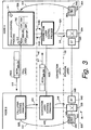
- Fig. 3 is a diagrammatic view of a telecommunications network utilizing a call layer and connection layer binding scheme according to a third embodiment of the invention.
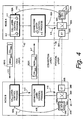
- Fig. 4 is a diagrammatic view of a telecommunications network utilizing a call layer and connection layer binding scheme according to a fourth embodiment of the invention.
- In the following description, for purposes of explanation and not limitation, specific details are set forth such as particular architectures, interfaces, techniques, etc. in order to provide a thorough understanding of the present invention. However, it will be apparent to those skilled in the art that the present invention may be practiced in other embodiments that depart from these specific details. In other instances, detailed descriptions of well known devices, circuits, and methods are omitted so as not to obscure the description of the present invention with unnecessary detail.
- The present invention is described in the context of the example,
non-limiting telecommunications network 20 shown in Fig. 1. Thetelecommunications network 20 can be any suitable network, such as a core network or a radio access network (such as the UTRAN for a third generation wideband code division multiple (WCDMA) radio access network). Fig. 1 illustrates only two nodes oftelecommunications network 20, particularlynode 22A (also known as Node A) andnode 22B (also known as Node B). In the embodiments described herein, for sake of illustration it will be assumed that a call or connection is to be made between adevice 24A connected tonode 22A and adevice 24B connected tonode 22B. In view of this illustrative assumption,node 22A andnode 22B are referred to herein as "end nodes". Thedevices - The
telecommunications network 20 has a physical layer which is illustrated in Fig. 1 as being below dashed double-dottedline 30. The physical layer comprises a network of switches and cables or links (e.g., trunk lines) which are employed to connect devices such asdevices such switches switch 32A being situated atend node 22A and switch 32B being situated atend node 22B. - To certain switch ports of
switch 32A which are outgoing fromend node 22A are connectedextension terminals 34A, only onesuch extension terminal 34A being shown in Fig. 1 for sake of simplification. Likewise, the outgoing switch ports ofswitch 32B are connected toextension terminals 34B. As is understood to those skilled in the art, tt is through extension terminals such asextension terminal 34A andextension terminal 34B that a switch 32 of a node in the physical layer is connected is the physical layer to other nodes, Various aspects of extension terminals (sometimes referred to as "exchange terminals") are described, e.g., in one or more of the following (all of which are incorporated herein by reference:United States Patent 6,128,295 ;United States Patent 6,088,359 ;United States Patent 5,963,553 ;United States Patent 6,154,459 ; andUnited States Patent 6,034,958 . For example, each extension terminal 34 may be connected to one or more (e.g., four) cables or links to other nodes oftelecommunications network 20. - The person skilled in the art will appreciate that the
telecommunications network 20 typically includes many unillustrated nodes other thannodes extension terminal 34A being connected to alink 36A leading externally fromnode 22A, and on the other hand showsextension terminal 34B being connected to alink 36B leading externally fromnode 22B. While it is possible thatextension terminal 34A andextension terminal 34B can be connected directly (e.g., link 36A and link 36B being essentially the same link), it is more likely thatlinks telecommunications network 20, for which reason links 36A and 36B are shown as broken lines in Fig. 1. - A switch such as
switch 32A innode 22A and switch 32B innode 22B has plural switch ports. A switch port can have an extension terminal connection thereto as above described. Alternatively, a switch port can have a device card or device board 35 connected thereto. Fig. 1 shows adevice board 35A connected to a switch port ofswitch 32A anddevice board 35B connected to a switch port ofswitch 32B. Each device board 35 can house or have mounted thereon several devices. For sake of simplicity, Fig. 1 shows only one device mounted on each switch board, e.g.,device 24A mounted ondevice board 35A anddevice 24B mounted ondevice board 35B. Each device 24 can, in turn, accommodate or house several connection endpoints. For example, a diversity handover device can handle four connection endpoints (e.g., comparing information received on three connection endpoints from up to three base stations and then forwarding the best received signal to the core network using a fourth connection endpoint). Again for sake of ease of illustration, only one connection endpoint is shown for each device board 35, e.g.,connection endpoint 36A indevice board 35A andconnection endpoint 36B indevice board 35B. - The information used to identify a connection endpoint, known herein as connection endpoint information, varies from switch to switch, and depends on conventions of the switch vendor/manufacturer. The connection endpoint information can thus be vendor specific for a physical layer entity, and may take the form of a concatenation of one or more of a node identifier, a hardware cabinet rack, a hardware slot, a hardware port, and a resource, for example.
- In the illustrated
telecommunications network 20, the switches 32 of the physical layer are Asynchronous Transfer Mode (ATM) switches. Various aspects of ATM-based telecommunications and represented example utilizations are described in the following:U.S. Patent Applications SN 09/188,101 [PCT/SE98/02325 09/188,265 PCT/SE98/02326 U.S. Patent Application SN 09/188,102 [PCT/SE98/02249 - The
telecommunications network 20 has a separation between its connection layer and its call layer. The connection layer is shown in Fig. 1 above the physical layer, e.g., between dashed double-dottedline 30 and dash dottedline 40. In each node oftelecommunications network 20, the connection layer includes a connection layer control process. For example, a connectionlayer control process 42A is illustrated in Fig. 1 fornode 22A, while a connectionlayer control process 42B is illustrated fornode 22B. - The call layer is shown in Fig. 1 above the connection layer, e.g., above dash dotted
line 40. In each node oftelecommunications network 20, the call layer includes a connection layer control process. Again by way of example, a calllayer control process 52A is illustrated in Fig. 1 fornode 22A, while a calllayer control process 52B is illustrated fornode 22B. - In general, whenever a user plane connection is needed to be set up in the physical layer, an order is given in the form of a connection request from the call layer to the connection layer. The connection endpoints of the application specific resources must be addressable at the connection layer. The connection is established using an appropriate connection layer signaling protocol, e.g., B-ISUP signaling for ATM connections or Q.AAL2 for AAL2 connections. The connection layer signaling is routed through the connection layer and controls reservation and through connection of connection layer resources (e.g., switches and extension terminals) along the path to the destination end node.
- In accordance with the general scheme as summarized above, the present invention provides various binding information techniques when the call and the connection layers are separated in a telecommunications network such as
telecommunications network 20, e.g., in a telecommunications network in which the call layer and the connection layer utilize differing signaling entities in the physical layer. Four embodiments of binding information techniques are described with reference to Fig. 1 - Fig. 4, respectively. - Some of the embodiments described herein utilize or refer to an ATM end system address (AESA). The concept of ATM end system address is described, e.g., in section 3.0 of ATM User-Network Interface (UNI) Signaling Specification, Version 4.0, af-sig-0061.00, July 1996, generated by the ATM Forum Technical Committee, which specifies the use of standard ATM addresses for private and public networks. In general, and AESA has an initial domain part (IDP) and a domain specific part (DSP). The initial domain part (IDP) comprises two fields: the authority and format identifier (AFI) and the initial domain identifier (IDI). The domain specific part (DSP) is subdivided into a high order DSP (HO-DSP) and a low order part which consists of the end system identifier (ESI) and a selector (SEL).
- In a first embodiment of the invention, described with reference to basic actions shown in Fig. 1, one AESA per node is utilized, along with binding information to bind the connection to a connection endpoint. As action 1-1, at
node 22A the call layer (more specifically calllayer control process 52A) reserves a connection endpoint (e.g.,connection endpoint 36A) in response to a request (action 1-0) bydevice 24A to set up a call withdevice 24B. The connection endpoint is' described by connection endpoint information which, as mentioned above, can be vendor specific information. In Fig. 1, the connection endpoint information is represented by CEI36. - As action 1-2A and action 1-2B, the call layer requests and obtains from the connection layer certain binding information which is associated with the connection endpoint information for the first connection end point at
node 22A. In one version of the first embodiment, action 1-2A can be performed by, e.g., by calllayer control process 52A requesting, from connectionlayer control process 42A, binding information (denoted as BI36 in Fig. 1) which is associated with the connection endpoint information CEI36 forconnection endpoint 36A. The connectionlayer control process 42A maintains a table 70 which keeps track of what binding information identifier (e.g., BI36) is associated with the connection endpoint information for the connection endpoint for which binding information is requested by action 1-2A. Action 1-2B shows the binding information associated with the connection endpoint information being returned by connectionlayer control process 42A to calllayer control process 52A. - To some extent, the binding information utilized in the first embodiment is standardized for Q.AAL2. In particular, the binding information is standardized in ITU-T Q.2630.1 to be a fixed size field of four octets. The binding information is named "Served User Generated Reference" (SUGR) in the Q.2630.1 specification. However, the ITU-T Q.2630.1 standard does not limit or imply anything regarding how those values are assigned to the SUGR.
- As action 1-3 the call
layer control process 52A of theend node 22A transmits a call layer signaling message to endnode 22B. In this first embodiment of the invention, the call layer signaling message 80(1) of action 1-3 includes the binding information and an ATM end system address (AESA) ofend node 22A, depicted as AESA22A in Fig. 1. The call layer signaling message 80(1) of action 1-3 can be in the form of an appropriate existing protocol, such as RANAP, RNSAP, and NBAP when thetelecommunications network 20 is a radio access network known as UTRAN. In any call and connection separated network the call layer must extend this information in order to make it possible for the connection layer to route the connection. As is understood generally and illustrated subsequently, the AESA ofend node 22A carried in the call layer signaling message 80(1) is used for signal routing to endnode 22A. - Upon receipt of the call layer signaling message 80(1), as action 1-4 the call
layer control process 52B ofend node 22B reserves a connection endpoint for the call todevice 24B. As explained previously, the connection endpoint is a user plane service access point on the device. As illustrated in Fig. 1, the particular connection endpoint ondevice 24B reserved by action 1-4 isconnection endpoint 36B. Thereafter, as action 1-5, the calllayer control process 52B sends a connection request message or primitive to the connection layer. The connection request message sent to the connection layer as action 1-5 includes the AESA ofend node 22A, the binding information (BI36), and the connection endpoint reserved at action 1-3 (e.g., connection endpoint 36B). - As a result of receipt of the connection request of action 1-5, as action 1-6 the connection
layer control process 42B handles theextension terminal 34B and through connectsswitch 32B so thatendpoint 36B is connected toextension terminal 34B. This handling involves resource handling, such as (for example) reserving CID and bandwidth on an available AAL2 path in the AAL2 case. - Action 1-7 involves the routing of connection layer signaling through the connection layer from end
node end node 22B to endnode 22A. The connection layer signaling, depicted as message 82(1) in Fig. 1, includes the binding information (BI36) and the AESA ofend node 22A (e.g., AESA22A). The connection layer signaling message 82(1) can be in any of several protocols, including Q.AAL2, B-ISUP, and PNNI. - Upon receipt of the connection layer signaling (e.g., message 82(1)), the connection
layer control process 42A in the connection layer atend node 22A accesses the binding information (e.g., BI36) included therein. Using the binding information obtained from the connection layer signaling, as action 1-8 the connectionlayer control process 42A accesses table 70 to obtain the appropriate connection endpoint information, i.e., the connection endpoint information CEI36 forconnection endpoint 36A. Then, using the vendor-specific connection endpoint information CEI36 acquired from table 70, the connectionlayer control process 42A issues signals to through connectswitch 32A, so connection endpoint associated with the connection endpoint information CEI36 is through connected todevice 24A. - In addition to the foregoing, when the connection layer signaling message 82(1) reaches its destination, e.g.,
end node 22A,end node 22A signals back to the originating node (e.g.,end node 22B) with a confirmation of receipt, and hence of establishment of the connection. The confirmation indicates that the path through the connection layer is through connected. Theend node 22A does not necessarily have to know the source address of the connection (e.g., the source address ofend node 22B). - What has been described above with reference to Fig. 1 is but a first of several alternative modes or implementations of the first embodiment. In the first mode of Fig. 1, the binding information is obtained by the call layer from conversion table 70 (see action 1-2A and action 1-2B), with conversion table 70 being handled by the connection layer.
- In another mode of the first embodiment, illustrated in Fig. 1A, the conversion table 70A is instead handled by the call layer, e.g., by call
layer control process 52A. Accordingly, action 1-2 involves calllayer control process 52A obtaining the binding information for the connection endpoint. Moreover, in this second mode of the first embodiment, upon receipt of the connection layer signaling which is sent to the first end node as action 1-7, at the first end node the connectionlayer control process 42A sends the binding information to the call layer, e.g., to calllayer control process 52A as depicted by action 1-8(1)A. The call layer then obtains the connection endpoint information for the first connection endpoint from the table 70A which is maintained by the call layer. Further, as action 1-8(2)A the call layer and orders the connection layer to through connect the switch in the physical layer of the first end node in accordance with the connection endpoint information retrieved from table 70A. Action 1-9 of Fig. 1A shows the connection layer directing the through connecting of theswitch 32A. - The first embodiment of the invention advantageously requires only the one AESA address -- AESA22A -- to be transported. Moreover, the binding information can be generic, and the conversion of the binding information to a vendor-specific connection endpoint address is performed within the node. For the first embodiment, the signaling standards must be able to accommodate the binding information.
- The second embodiment is illustrated in Fig. 2, which employs similarly referenced elements as Fig. 1. In the second embodiment, an ATM end system address (AESA) is associated with a first connection end point at the first end node. In terms of Fig. 2, AESA36A is the ATM end system address (AESA) which is associated with a first connection end point (e.g.,
connection endpoint 36A). - In accordance with operation of the second embodiment, as action 2-1 the call layer (more specifically call
layer control process 52A ofnode 22A) reserves a connection endpoint (e.g.,connection endpoint 36A) in response to a request (action 2-0) bydevice 24A to set up a call withdevice 24B. Then, as action 2-2, the calllayer control process 52A determines the AESA for thefirst connection endpoint 36A. Such determination or assigning of an AESA to each connection endpoint can occur by management operation or (more preferably) an internal algorithm which, at start up of the node, assigns AESAs within an address range to the connection endpoints of the node. - As action 2-3 the call
layer control process 52A of theend node 22A transmits a call layer signaling message to endnode 22B. In this second embodiment of the invention, the call layer signaling message 80(2) of action 2-3 includes the AESA (AESA36A). Again, as is the case with all other embodiments herein specifically described, the call layer signaling message 80(2) of action 2-3 can be in the form of an appropriate existing protocol, such as RANAP, RNSAP, and NBAP when thetelecommunications network 20 is a radio access network known as UTRAN. - Upon receipt of the call layer signaling message 80(2), as action 2-4 the call
layer control process 52B ofend node 22B reserves a connection endpoint for the call todevice 24B. As illustrated in Fig. 2, the particular connection endpoint reserved by action 2-4 isconnection endpoint 36B. Thereafter, as action 2-5, the calllayer control process 52B sends a connection request message to the connection layer. The connection request message sent to the connection layer as action 2-5 includes the AESA (the AESA36A of thefirst connection endpoint 36A). As a result of receipt of the connection request of action 2-5, as action 2-6 the connectionlayer control process 42B handles theextension terminal 34B and through connectsswitch 32B so thatendpoint 36B is connected toextension terminal 34B. - Action 2-7 involves the routing of connection layer signaling through the connection layer from end
node end node 22B to endnode 22A. The connection layer signaling, depicted as message 82(2) in Fig. 2, includes the AESA36A of thefirst connection endpoint 36A. In fact, the AESA36A is used as the ultimate address for routing the connection layer signaling. Upon receipt of the connection layer signaling (e.g., message 82(1)), as reflected by action 2-8 the connectionlayer control process 42A in the connection layer atend node 22A knows to what connection endpoint the connection layer signaling message pertains in view of the AESA included therein. The connectionlayer control process 42A uses the AESA to issue a command (action 2-9) to switch 32A so as to through connect the ATM switch to the first connection endpoint, e.g., to theconnection endpoint 36A fordevice 24A. - An advantage of this second embodiment is that the signaling standards need not support binding information of the type of the first, embodiment. Thus, the second embodiment can be used when the call layer signaling cannot carry a binding information attribute. However, the second embodiment does require an AESA address for each connection endpoint, which also has to be configured or assigned as above described.
- The third example embodiment is illustrated in Fig. 3, which again employs similarly referenced elements as Fig. 1. In the third embodiment, one ATM end system address (AESA), known as a dynamic AESA, is associated both with a first end node of the network and with a first connection end point at the first end node. The dynamic AESA is reusable for association with other connection end points at the first end node for other calls. In view of this potentially repeated use of a particular dynamic AESA value for other connection end points for other calls, a table 70C is maintained at the first end node for keeping track for which connection end point any particular dynamic AESA is currently being used.
- Table 70C as shown in Fig. 3 lists several dynamic AESA values, of which only two representative dynamic AESA values are shown (AESA22A-DX and AESA22A-DY). Each dynamic AESA value in Table 70C is associated with an end node and, at least temporarily, with a connection endpoint of that end node. For sake of illustration, Table 70C shows as its second column the end node with which its dynamic AESA values are associated. This second column in not really necessary in Table 70C in view of the fact that call
layer control process 52A knows to which end node the Table 70C pertains. The third column of Table 70C contains the particular connection endpoint with which each dynamic AESA is associated - In accordance with operation of the third embodiment, as action 3-1 the call layer reserves a connection endpoint (e.g.,
connection endpoint 36A) in similar manner as with the previous embodiments (e.g., in response to a request (action 3-0) bydevice 24A to set up a call withdevice 24B). Then, as action 3-2, the calllayer control process 52A obtains an available one of the dynamic AESAs from Table 70C for the call, and for that available dynamic AESA stores in its third column an identifier for the connection endpoint (connection endpoint 36A) involved in the call for the calling party. For the example shown in Fig. 3, the calllayer control process 52A obtains from Table 70C the dynamic AESA having the value AESA22A-DX). - As action 3-3 the call
layer control process 52A of theend node 22A transmits a call layer signaling message to endnode 22B. In this second embodiment of the invention, the call layer signaling message 80(3) of action 3-3 includes the dynamic AESA value. Again, the call layer signaling message 80(3) of action 2-3 can take the form(s) as described above. - Upon receipt of the call layer signaling message 80(3), as action 3-4 the call
layer control process 52B ofend node 22B reserves a connection endpoint for the call todevice 24B. As illustrated in Fig. 3, the particular connection endpoint reserved by action 2-4 isconnection endpoint 36B. Thereafter, as action 3-5, the calllayer control process 52B sends a connection request message to the connection layer. The connection request message sent to the connection layer as action 3-5 includes the dynamic AESA (e.g., the dynamic AESA having the value AESA22A-DX in the present example). As a result of receipt of the connection request of action 3-5, as action 3-6 the connectionlayer control process 42B handles theextension terminal 34B and through connectsswitch 32B so thatendpoint 36B is connected toextension terminal 34B. - Action 3-7 involves the routing of connection layer signaling through the connection layer from end
node end node 22B to endnode 22A. The connection layer signaling, depicted as message 82(3) in Fig. 3, includes the dynamic AESA. In fact, the dynamic AESA is used as the end node address for routing the connection layer signaling. Upon receipt of the connection layer signaling (e.g., message 82(3)), as reflected by action 3-8A the connectionlayer control process 42A in the connection layer sends the dynamic AESA value to the calllayer control process 52A. The calllayer control process 52A can then check Table 70C to determined which connection endpoint is currently specified by the received dynamic AESA, and returns to connectionlayer control process 42A an identification of the appropriate connection endpoint as action 3-8B. The connectionlayer control process 42A then uses the connection endpoint identifier to issue a command (action 3-9) to switch 32A so as to through connect the ATM switch to the connection endpoint, e.g., to theconnection endpoint 36A fordevice 24A. - In the above description of the third embodiment, a dynamic AESA value has been employed for sake of illustration. It should be understood that a routing number other than an AESA can be utilized for the third embodiment consistent with the principles summarized above.
- The fourth example embodiment is illustrated in Fig. 4, which again employs similarly referenced elements as Fig. 1. In the fourth embodiment, connection endpoint information for a first connection end point of a first end node of the network is included in a vacant or otherwise unused field in an ATM end system address (AESA) of the first end node. In like manner as previous embodiment, the connection layer signaling is routed to the first end node from a second end node. The connection layer signaling of the fourth embodiment includes the AESA of the first end node, which also includes the connection endpoint information. At the first end node, the connection endpoint information for the first connection end point of the first end node (included in the AESA of the first end node) is used to through connect the ATM switch in the physical layer to the first connection endpoint.
- In accordance with operation of the fourth embodiment, as action 4-1 the call layer reserves a connection endpoint (e.g.,
connection endpoint 36A) in similar manner as with the previous embodiments (e.g., in response to a request (action 4-0) bydevice 24A to set up a call withdevice 24B). Then, as action 4-2, the calllayer control process 52A associates a connection endpoint identifier with the connection endpoint. For sake of illustration, in Fig. 4 the connection endpoint identifier CEI36 is assigned forconnection endpoint 36A. As part of action 4-2, calllayer control process 52A prepares a call layer signaling message to be transmitted to endnode 22B. The AESA for theend node 22A is to be included in the call layer signaling message of the fourth embodiment. However, in the fourth embodiment the calllayer control process 52A includes the connection endpoint identifier for the connection endpoint for the calling party in an empty or vacant field of the AESA forend node 22A. In particular, in the present example the connection endpoint identifier CEI36 is included in a vacant field of the AESA forend node 22A. An example vacant field could be, for example, an ESI field when using the AESA E.164 address format. - As action 4-3 the call
layer control process 52A of theend node 22A transmits the call layer signaling message to endnode 22B. As shown in Fig. 4, in this fourth embodiment of the invention the call layer signaling message 80(4) of action 4-3 includes the AESA for the first end node, and further includes in that AESA the connection endpoint identifier CEI36 for the first connection endpoint. - Upon receipt of the call layer signaling message 80(4), as action 4-4 the call
layer control process 52B ofend node 22B reserves a connection endpoint for the call todevice 24B. As illustrated in Fig. 4, the particular connection endpoint reserved by action 4-4 isconnection endpoint 36B. Thereafter, as action 4-5, the calllayer control process 52B sends a connection request message to the connection layer. The connection request message sent to the connection layer as action 4-5 includes the AESA of theend node 22A (which includes, e.g., connection endpoint identifier CEI36 for the first connection endpoint). As a result of receipt of the connection request of action 4-5, as action 4-6 the connectionlayer control process 42B handles theextension terminal 34B and through connectsswitch 32B so thatendpoint 36B is connected toextension terminal 34B. - Action 4-7 involves the routing of connection layer signaling through the connection layer from end
node end node 22B to endnode 22A. The connection layer signaling, depicted as message 82(4) in Fig. 4, includes the AESA for theend node 22A (which includes, e.g., connection endpoint identifier CEI36 for the first connection endpoint). In fact, the AESA forend node 22A is used for routing the connection layer signaling. - Upon receipt of the connection layer signaling (e.g., message 82(4)), as reflected by action 4-8 the connection
layer control process 42A in the connection layer unpacks the AESA forend node 22A, and obtains therefrom the connection endpoint identifier CEI36 for the first connection endpoint. The connectionlayer control process 42A then uses the connection endpoint identifier to issue a command (action 4-9) to switch 32A so as to through connect the ATM switch to the connection endpoint, e.g., to theconnection endpoint 36A fordevice 24A. - While the invention has been described in connection with what is presently considered to be the most practical and preferred embodiment, it is to be understood that the invention is not to be limited to the disclosed embodiment, but on the contrary, is intended to cover various modifications and equivalent arrangements included within the scope of the appended claims.
Claims (23)
- A method in a telecommunications network (20) having a physical layer which includes ATM entities, a connection layer with a separation between a call layer and a connection layer whereby the call layer and the connection layer utilize differing signaling entities in the physical layer, said method
characterized by
associating binding information (BI36) with connection endpoint information for a first connection end point (36A) at a first end node (22A) of the network;
in the call layer, transmitting the binding information (BI36) and an ATM end system address, hereinafter referred to as AESA, of the first end node (22A) to a second end node (22B) of the network;
reserving a second connection end point (36B) at the second end node (22B);
sending a connection request from the call layer to the connection layer, the connection request including the binding information (BI36) and the AESA of the first end node (22A);
routing connection layer signaling through the connection layer to the first end node (22A);
using at the first end node (22A) the binding information (BI36) included in the connection layer signaling to obtain the connection endpoint information for the first connection end point (36A). - The method of claim 1, further comprising the call layer obtaining the binding information (BI36) from the connection layer.
- The method of claim 1, whereby the step of using the binding information (BI36) to obtain the connection endpoint information for the first connection end point . (36A) involves, at the first end node (22A), transmitting the binding information (BI36) to the call layer at the call layer obtaining the connection endpoint information for the first connection endpoint (36A).
- The method of claim 3, further comprising the call layer ordering the connection layer to through-connect a switch (32A) in the physical layer of the first end node (22A) in accordance with the connection endpoint information for the first connection endpoint (36A).
- The method of claim 1, further comprising through-connecting a switch (32A) in the physical layer of the first end node (22A) in accordance with the connection endpoint information for the first connection endpoint (36A).
- The method of claim 1, further comprising the step of including connection end point information for a first connection end point (36A) of a first end node (22A) of the network in an ATM end system address, ASEA, of the first end node (22A).
- The method of claim 6, further comprising including the connection endpoint information for the first connection end point (36A) of the first end node (22A) of the network in a vacant field or unused field of the ATM end system address, AESA, of the first end node (22A).
- The method of claim 1, wherein the connection endpoint information for the first connection end point (36A) at the first end node (22A) of the network is vendor specific for a physical layer entity at the first end node (22A).
- The method of claim 8, wherein the connection endpoint information is a concatenation of one or more of a node identifier, a hardware cabinet rack, a hardware slot, a hardware port, and a resource.
- A method in a telecommunications network (20) having a physical layer which includes ATM entities, a connection layer with a separation between the call layer and the connection layer whereby the call layer and the connection layer utilize differing signaling entities in the physical layer, said method
characterized by
associating a dynamic routing number both with a first end node (22A) of the network (20) and with a first connection end point (36A) at the first end node (22A);
in the call layer, transmitting the dynamic routing number to a second end node (22B) of the network (20);
reserving a second connection end point (36B) at the second end node (22B);
sending a connection request from the call layer to the connection layer, the connection request including the dynamic routing number;
routing connection layer signaling through the connection layer to the first end node (22A);
using at the first end node (22A) the dynamic routing number included in the connection layer signaling to obtain the first connection end point (36A). - The method of claim 10, wherein the routing number is an ATM end system address, AESA.
- The method of claim 10, further comprising routing the connection layer signaling through the connection layer to the first end node (22A) using the dynamic routing number.
- The method of claim 10, further comprising through connecting a switch (32A) in the physical layer of the first end node (22A) in accordance with the connection endpoint information for the first connection endpoint (36A).
- The method of claim 10, wherein the connection endpoint information for the first connection end point (36A) at the first end node (22A) of the network is vendor specific for a physical layer entity at the first end node (22A).
- The method of claim 14, wherein the connection endpoint information is a concatenation of one or more of a node identifier, a hardware cabinet rack, a hardware slot, a hardware port, and a resource.
- A first end node (22A) in a telecommunications network (20) including said first end node (22A) and a second end node (22B) which are connected by separated call and connection layers,
characterized in
means (70A) for associating binding information (BI36) with connection endpoint information for a first connection end point (36A) at the first end node (22A);
means (52A) for transmitting the binding information (BI36) through the call layer to a second end node (22B);
means (42A) for using, upon receipt of a connection layer signaling routed from the second end node to the first end node through the connection layer, the binding information (BI36) carried in the connection layer signaling from the second end node (22B) to the first end node (22A) to obtain the connection endpoint information for the first connection end point (36A). - The node of claim 16, further comprising a physical layer having a first ATM switch (32A) wherein the node (22A) through-connects the first ATM switch (32A) in accordance with the connection endpoint information for the first connection endpoint (36A).
- The node of claim 17, further comprising a call layer process (52A) which obtains the binding information from the connection layer.
- The node of claim 16, further comprising means for transmitting the binding information to a call layer process (52A) at the call layer to obtain the connection endpoint information for the first connection endpoint (36A).
- The node of claim 16, wherein the connection endpoint information for the first connection end point (36A) at the first end node (22A) of the network is vendor specific for a physical layer entity at the first end node (22A).
- The node of claim 21, wherein the connection endpoint information is a concatenation of one or more of a node identifier, a hardware cabinet rack, a hardware slot, a hardware port, and a resource.
- A first end node (22A) in a telecommunications network (20) including said first end node (22A) and a second end node (22B) which are connected by separated call and connection layers,
characterized in
means (70C) for associating a dynamic routing number both with the first end node (22A) of the network and with a first connection end point (36A) at the first end node (22A);
means (52A) for transmitting the dynamic routing number to the second end node (22B);
means (42A) for using, upon receipt of connection layer signaling routed through the connection layer from the second end node (22B) to the first end node (22A), the dynamic routing number to obtain the first connection end point (36A). - The node of claim 22, wherein the dynamic routing number is an ATM end system address, AESA, for the first end node (22A).
Applications Claiming Priority (5)
| Application Number | Priority Date | Filing Date | Title |
|---|---|---|---|
| US25711600P | 2000-12-22 | 2000-12-22 | |
| US257116P | 2000-12-22 | ||
| US09/829,451 US7016369B2 (en) | 2000-12-22 | 2001-04-10 | Binding information for telecommunications network |
| US829451 | 2001-04-10 | ||
| PCT/SE2001/002819 WO2002052867A2 (en) | 2000-12-22 | 2001-12-18 | Binding information for telecommunications network |
Publications (2)
| Publication Number | Publication Date |
|---|---|
| EP1344410A2 EP1344410A2 (en) | 2003-09-17 |
| EP1344410B1 true EP1344410B1 (en) | 2007-08-22 |
Family
ID=26945812
Family Applications (1)
| Application Number | Title | Priority Date | Filing Date |
|---|---|---|---|
| EP01272410A Expired - Lifetime EP1344410B1 (en) | 2000-12-22 | 2001-12-18 | Binding information for telecommunications network |
Country Status (6)
| Country | Link |
|---|---|
| US (2) | US7016369B2 (en) |
| EP (1) | EP1344410B1 (en) |
| AT (1) | ATE371340T1 (en) |
| DE (1) | DE60130141T2 (en) |
| ES (1) | ES2291273T3 (en) |
| WO (1) | WO2002052867A2 (en) |
Families Citing this family (4)
| Publication number | Priority date | Publication date | Assignee | Title |
|---|---|---|---|---|
| FI105438B (en) * | 1998-09-21 | 2000-08-15 | Nokia Networks Oy | Connection connection in a wireless telecommunications network |
| US7327740B2 (en) * | 2001-05-25 | 2008-02-05 | Telefonaktiebolaget Lm Ericsson (Publ) | Facilitating reliable connection admission control for telecommunications system using AAL2 signaling |
| WO2003030490A2 (en) * | 2001-09-27 | 2003-04-10 | Nokia Corporation | Method and network node for providing security in a radio access network |
| EP1475941A1 (en) * | 2003-05-08 | 2004-11-10 | Harman/Becker Automotive Systems GmbH | Scalable service provision to a vehicle entertainment and information processing device |
Family Cites Families (52)
| Publication number | Priority date | Publication date | Assignee | Title |
|---|---|---|---|---|
| US570882A (en) * | 1896-11-03 | rowand | ||
| JPH0628361B2 (en) | 1984-11-27 | 1994-04-13 | 国際電信電話株式会社 | Packet exchange method |
| US5740156A (en) | 1986-09-16 | 1998-04-14 | Hitachi, Ltd. | Packet switching system having self-routing switches |
| US4973956A (en) | 1988-12-22 | 1990-11-27 | General Electric Company | Crossbar switch with distributed memory |
| CA1320257C (en) | 1989-04-20 | 1993-07-13 | Ernst August Munter | Method and apparatus for input-buffered asynchronous transfer mode switching |
| EP0405042B1 (en) | 1989-06-29 | 1994-09-14 | International Business Machines Corporation | High speed digital packet switching system |
| CA2015514C (en) | 1989-08-22 | 1996-08-06 | Mitsuru Tsuboi | Packet switching system having bus matrix switch |
| JP2531275B2 (en) | 1989-09-29 | 1996-09-04 | 日本電気株式会社 | ATM cell transfer method |
| JPH03182140A (en) | 1989-12-11 | 1991-08-08 | Mitsubishi Electric Corp | Common buffer type exchange |
| US5150358A (en) | 1990-08-23 | 1992-09-22 | At&T Bell Laboratories | Serving constant bit rate traffic in a broadband data switch |
| US5144293A (en) | 1990-12-18 | 1992-09-01 | International Business Machines Corporation | Serial link communication system with cascaded switches |
| SE469812B (en) * | 1992-02-10 | 1993-09-13 | Ericsson Telefon Ab L M | Bit oriented digital coupler and general digital coupler for PCM transmission systems |
| WO1993019559A1 (en) | 1992-03-21 | 1993-09-30 | Roke Manor Research Limited | Atm radio network |
| MX9308193A (en) | 1993-01-29 | 1995-01-31 | Ericsson Telefon Ab L M | CONTROLLED ACCESS ATM SWITCH. |
| JP3357423B2 (en) | 1993-06-15 | 2002-12-16 | 富士通株式会社 | Control system for equipment with switching system |
| CA2124379C (en) | 1993-06-25 | 1998-10-27 | Thomas F. La Porta | Distributed processing architecture for control of broadband and narrowband communications networks |
| DE4341888C1 (en) | 1993-12-08 | 1995-04-06 | Siemens Ag | Method for controlling components of a communications system |
| US5491693A (en) | 1993-12-30 | 1996-02-13 | International Business Machines Corporation | General transport layer gateway for heterogeneous networks |
| JP3405800B2 (en) | 1994-03-16 | 2003-05-12 | 富士通株式会社 | ATM-based variable-length cell transfer system, ATM-based variable-length cell switch, and ATM-based variable-length cell switch |
| JPH07297830A (en) | 1994-04-21 | 1995-11-10 | Mitsubishi Electric Corp | Multiplexer, demultiplexer, switching device, and network adapter |
| GB9408574D0 (en) | 1994-04-29 | 1994-06-22 | Newbridge Networks Corp | Atm switching system |
| SE511848C2 (en) | 1994-09-12 | 1999-12-06 | Ericsson Telefon Ab L M | Resource separation in a service and connection separated network |
| WO1996017306A2 (en) * | 1994-11-21 | 1996-06-06 | Oracle Corporation | Media server |
| US5724348A (en) | 1995-04-05 | 1998-03-03 | International Business Machines Corporation | Efficient hardware/software interface for a data switch |
| US5568749A (en) * | 1995-04-06 | 1996-10-29 | Ford Motor Company | Automotive accelerator return spring damper |
| US5499239A (en) | 1995-04-14 | 1996-03-12 | Northern Telecom Limited | Large capacity modular ATM switch |
| SE505845C2 (en) | 1995-04-24 | 1997-10-13 | Ericsson Telefon Ab L M | Telecommunication systems and ways of transmitting microcells in this |
| US5680390A (en) | 1995-06-06 | 1997-10-21 | Bell Communications Research, Inc. | Broadband telecommunications network and method of having operations systems support |
| US5963564A (en) | 1995-06-13 | 1999-10-05 | Telefonaktiebolaget Lm Ericsson | Synchronizing the transmission of data via a two-way link |
| US5710882A (en) | 1995-06-29 | 1998-01-20 | Telefonaktiebolaget Lm Ericsson | Method and call set up server for setting up a call using a call handling portion and a connection handling portion to handle the call and the connection, respectively |
| JPH09270804A (en) | 1996-04-03 | 1997-10-14 | Toshiba Corp | ATM switch |
| KR100358032B1 (en) | 1996-03-08 | 2004-06-05 | 가부시키가이샤 엔.티.티.도코모 | Short cell multi-Tx transmission system and transmission method |
| US5790541A (en) | 1996-04-01 | 1998-08-04 | Motorola, Inc. | Apparatus, method, system and system method for distributed routing in a multipoint communication system |
| SE506475C2 (en) | 1996-04-26 | 1997-12-22 | Ericsson Telefon Ab L M | Service and connection separated network |
| GB2314995B (en) | 1996-07-05 | 2000-11-01 | Northern Telecom Ltd | Telecommunication system |
| US5946309A (en) | 1996-08-21 | 1999-08-31 | Telefonaktiebolaget Lm Ericsson | Hybrid ATM adaptation layer |
| US6088389A (en) * | 1997-05-13 | 2000-07-11 | Lucent Technologies, Inc. | System and method for training a plurality of equalizers and a modem employing the system or method |
| US6088359A (en) | 1997-07-11 | 2000-07-11 | Telefonaktiebolaget Lm Ericsson | ABR server |
| US6034958A (en) | 1997-07-11 | 2000-03-07 | Telefonaktiebolaget Lm Ericsson | VP/VC lookup function |
| US5963553A (en) | 1997-07-11 | 1999-10-05 | Telefonaktiebolaget Lm Ericsson | Handling ATM multicast cells |
| US6128295A (en) | 1997-07-11 | 2000-10-03 | Telefonaktiebolaget Lm Ericsson | Buffering of point-to-point and/or point-to-multipoint ATM cells |
| US6154459A (en) | 1997-07-11 | 2000-11-28 | Telefonaktiebolaget Lm Ericsson | Data shaper for ATM traffic |
| US5987515A (en) | 1997-08-29 | 1999-11-16 | International Business Machines Corporation | Internet protocol assists using multi-path channel protocol |
| JPH11122271A (en) * | 1997-10-09 | 1999-04-30 | Nec Corp | Dynamic ATM address setting method |
| US6483381B1 (en) * | 1997-10-22 | 2002-11-19 | Jeng-Jye Shau | Signal transmission and receiving methods optimized for integrated circuit implementation |
| CA2221546A1 (en) * | 1997-11-19 | 1999-05-19 | Northern Telecom Limited | A telephony system and method of signalling |
| US6009103A (en) | 1997-12-23 | 1999-12-28 | Mediaone Group, Inc. | Method and system for automatic allocation of resources in a network |
| US7227837B1 (en) * | 1998-04-30 | 2007-06-05 | At&T Labs, Inc. | Fault tolerant virtual tandem switch |
| US6195714B1 (en) * | 1998-06-08 | 2001-02-27 | Nortel Networks Limited | System for transferring STM calls through ATM network by converting the STM calls to ATM and vice versa at the edge nodes of ATM network |
| WO2000039971A1 (en) * | 1998-12-29 | 2000-07-06 | Unisphere Solutions, Inc. | Method and apparatus for provisioning inter-machine trunks |
| US6741585B1 (en) * | 2000-05-05 | 2004-05-25 | Lucent Technologies Inc. | Interworking of addressing in an internetwork |
| US7072329B2 (en) | 2000-05-22 | 2006-07-04 | Telefonaktiebolaget Lm Ericsson (Publ) | Combining differing transport technologies in a telecommunications system |
-
2001
- 2001-04-10 US US09/829,451 patent/US7016369B2/en not_active Expired - Lifetime
- 2001-12-18 AT AT01272410T patent/ATE371340T1/en not_active IP Right Cessation
- 2001-12-18 EP EP01272410A patent/EP1344410B1/en not_active Expired - Lifetime
- 2001-12-18 DE DE60130141T patent/DE60130141T2/en not_active Expired - Lifetime
- 2001-12-18 WO PCT/SE2001/002819 patent/WO2002052867A2/en not_active Ceased
- 2001-12-18 ES ES01272410T patent/ES2291273T3/en not_active Expired - Lifetime
-
2005
- 2005-10-03 US US11/240,362 patent/US20060067355A1/en not_active Abandoned
Also Published As
| Publication number | Publication date |
|---|---|
| DE60130141T2 (en) | 2008-05-15 |
| US20040202172A1 (en) | 2004-10-14 |
| ATE371340T1 (en) | 2007-09-15 |
| DE60130141D1 (en) | 2007-10-04 |
| EP1344410A2 (en) | 2003-09-17 |
| WO2002052867A3 (en) | 2003-01-03 |
| US7016369B2 (en) | 2006-03-21 |
| US20060067355A1 (en) | 2006-03-30 |
| ES2291273T3 (en) | 2008-03-01 |
| WO2002052867A2 (en) | 2002-07-04 |
Similar Documents
| Publication | Publication Date | Title |
|---|---|---|
| RU2144208C1 (en) | Wide-band communication system | |
| KR100579031B1 (en) | Bearer Independent Signaling Protocol | |
| CA2015932C (en) | Mobile communications system | |
| FI105438B (en) | Connection connection in a wireless telecommunications network | |
| US7085264B2 (en) | System and method for controlling media gateways that interconnect disparate networks | |
| US6788691B1 (en) | AAL2 negotiation procedure | |
| US7016369B2 (en) | Binding information for telecommunications network | |
| EP1151585B1 (en) | Establishing internal control paths in an atm node | |
| US20020181487A1 (en) | Automation of provisioning of private line packet network connections | |
| EP0853854B1 (en) | Method and means for multiconnection call signalling | |
| US20030118037A1 (en) | Apparatus and method for interworking switching system network | |
| KR100540892B1 (en) | Method and device for connection between frame relay network and ATM network in distributed environment | |
| KR20000013859A (en) | Address converting method between public network adress and asynchronous transfer mode end system address | |
| KR100221495B1 (en) | Subscriber call connecting method of an atm exchange | |
| KR100275510B1 (en) | Internal originating call control mathod for the atm subscriber | |
| KR100275511B1 (en) | Internal terminating call control mathod for the atm subscriber | |
| KR100205026B1 (en) | Subscriber call / connection establishment apparatus and method in asynchronous transfer mode exchanger | |
| FI105747B (en) | Multiple switching center data network | |
| US20010043590A1 (en) | Telecommunications networks | |
| JP3153164B2 (en) | Intra-network call identification method | |
| EP1060636A2 (en) | Improvements in, or relating to, atm mobile networks | |
| Loukas et al. | Signaling and mobility control for wireless intelligent ATM CPNs | |
| KR100353707B1 (en) | Method and apparatus for providing internet protocol service in asynchronous transfer mode network | |
| JPH0583302A (en) | Information communication system | |
| KR20010054038A (en) | Method for fixing call in a asynchronous transfer mode exchange |
Legal Events
| Date | Code | Title | Description |
|---|---|---|---|
| PUAI | Public reference made under article 153(3) epc to a published international application that has entered the european phase |
Free format text: ORIGINAL CODE: 0009012 |
|
| 17P | Request for examination filed |
Effective date: 20030603 |
|
| AK | Designated contracting states |
Kind code of ref document: A2 Designated state(s): AT BE CH CY DE DK ES FI FR GB GR IE IT LI LU MC NL PT SE TR |
|
| AX | Request for extension of the european patent |
Extension state: AL LT LV MK RO SI |
|
| RAP1 | Party data changed (applicant data changed or rights of an application transferred) |
Owner name: TELEFONAKTIEBOLAGET LM ERICSSON (PUBL) |
|
| 17Q | First examination report despatched |
Effective date: 20061002 |
|
| GRAP | Despatch of communication of intention to grant a patent |
Free format text: ORIGINAL CODE: EPIDOSNIGR1 |
|
| GRAS | Grant fee paid |
Free format text: ORIGINAL CODE: EPIDOSNIGR3 |
|
| GRAA | (expected) grant |
Free format text: ORIGINAL CODE: 0009210 |
|
| AK | Designated contracting states |
Kind code of ref document: B1 Designated state(s): AT BE CH CY DE DK ES FI FR GB GR IE IT LI LU MC NL PT SE TR |
|
| REG | Reference to a national code |
Ref country code: GB Ref legal event code: FG4D |
|
| REG | Reference to a national code |
Ref country code: CH Ref legal event code: EP |
|
| REG | Reference to a national code |
Ref country code: IE Ref legal event code: FG4D |
|
| REF | Corresponds to: |
Ref document number: 60130141 Country of ref document: DE Date of ref document: 20071004 Kind code of ref document: P |
|
| PG25 | Lapsed in a contracting state [announced via postgrant information from national office to epo] |
Ref country code: FI Free format text: LAPSE BECAUSE OF FAILURE TO SUBMIT A TRANSLATION OF THE DESCRIPTION OR TO PAY THE FEE WITHIN THE PRESCRIBED TIME-LIMIT Effective date: 20070822 Ref country code: NL Free format text: LAPSE BECAUSE OF FAILURE TO SUBMIT A TRANSLATION OF THE DESCRIPTION OR TO PAY THE FEE WITHIN THE PRESCRIBED TIME-LIMIT Effective date: 20070822 |
|
| NLV1 | Nl: lapsed or annulled due to failure to fulfill the requirements of art. 29p and 29m of the patents act | ||
| PG25 | Lapsed in a contracting state [announced via postgrant information from national office to epo] |
Ref country code: AT Free format text: LAPSE BECAUSE OF FAILURE TO SUBMIT A TRANSLATION OF THE DESCRIPTION OR TO PAY THE FEE WITHIN THE PRESCRIBED TIME-LIMIT Effective date: 20070822 Ref country code: CH Free format text: LAPSE BECAUSE OF FAILURE TO SUBMIT A TRANSLATION OF THE DESCRIPTION OR TO PAY THE FEE WITHIN THE PRESCRIBED TIME-LIMIT Effective date: 20070822 Ref country code: LI Free format text: LAPSE BECAUSE OF FAILURE TO SUBMIT A TRANSLATION OF THE DESCRIPTION OR TO PAY THE FEE WITHIN THE PRESCRIBED TIME-LIMIT Effective date: 20070822 |
|
| REG | Reference to a national code |
Ref country code: CH Ref legal event code: PL |
|
| REG | Reference to a national code |
Ref country code: ES Ref legal event code: FG2A Ref document number: 2291273 Country of ref document: ES Kind code of ref document: T3 |
|
| PG25 | Lapsed in a contracting state [announced via postgrant information from national office to epo] |
Ref country code: BE Free format text: LAPSE BECAUSE OF FAILURE TO SUBMIT A TRANSLATION OF THE DESCRIPTION OR TO PAY THE FEE WITHIN THE PRESCRIBED TIME-LIMIT Effective date: 20070822 |
|
| EN | Fr: translation not filed | ||
| PG25 | Lapsed in a contracting state [announced via postgrant information from national office to epo] |
Ref country code: DK Free format text: LAPSE BECAUSE OF FAILURE TO SUBMIT A TRANSLATION OF THE DESCRIPTION OR TO PAY THE FEE WITHIN THE PRESCRIBED TIME-LIMIT Effective date: 20070822 Ref country code: GR Free format text: LAPSE BECAUSE OF FAILURE TO SUBMIT A TRANSLATION OF THE DESCRIPTION OR TO PAY THE FEE WITHIN THE PRESCRIBED TIME-LIMIT Effective date: 20071123 |
|
| PG25 | Lapsed in a contracting state [announced via postgrant information from national office to epo] |
Ref country code: PT Free format text: LAPSE BECAUSE OF FAILURE TO SUBMIT A TRANSLATION OF THE DESCRIPTION OR TO PAY THE FEE WITHIN THE PRESCRIBED TIME-LIMIT Effective date: 20080122 |
|
| PLBE | No opposition filed within time limit |
Free format text: ORIGINAL CODE: 0009261 |
|
| STAA | Information on the status of an ep patent application or granted ep patent |
Free format text: STATUS: NO OPPOSITION FILED WITHIN TIME LIMIT |
|
| PG25 | Lapsed in a contracting state [announced via postgrant information from national office to epo] |
Ref country code: SE Free format text: LAPSE BECAUSE OF FAILURE TO SUBMIT A TRANSLATION OF THE DESCRIPTION OR TO PAY THE FEE WITHIN THE PRESCRIBED TIME-LIMIT Effective date: 20071122 |
|
| 26N | No opposition filed |
Effective date: 20080526 |
|
| PG25 | Lapsed in a contracting state [announced via postgrant information from national office to epo] |
Ref country code: MC Free format text: LAPSE BECAUSE OF NON-PAYMENT OF DUE FEES Effective date: 20071231 |
|
| PG25 | Lapsed in a contracting state [announced via postgrant information from national office to epo] |
Ref country code: IE Free format text: LAPSE BECAUSE OF NON-PAYMENT OF DUE FEES Effective date: 20071218 |
|
| PG25 | Lapsed in a contracting state [announced via postgrant information from national office to epo] |
Ref country code: FR Free format text: LAPSE BECAUSE OF NON-PAYMENT OF DUE FEES Effective date: 20071231 |
|
| PG25 | Lapsed in a contracting state [announced via postgrant information from national office to epo] |
Ref country code: CY Free format text: LAPSE BECAUSE OF FAILURE TO SUBMIT A TRANSLATION OF THE DESCRIPTION OR TO PAY THE FEE WITHIN THE PRESCRIBED TIME-LIMIT Effective date: 20070822 |
|
| PG25 | Lapsed in a contracting state [announced via postgrant information from national office to epo] |
Ref country code: LU Free format text: LAPSE BECAUSE OF NON-PAYMENT OF DUE FEES Effective date: 20071218 |
|
| PG25 | Lapsed in a contracting state [announced via postgrant information from national office to epo] |
Ref country code: TR Free format text: LAPSE BECAUSE OF FAILURE TO SUBMIT A TRANSLATION OF THE DESCRIPTION OR TO PAY THE FEE WITHIN THE PRESCRIBED TIME-LIMIT Effective date: 20070822 |
|
| PG25 | Lapsed in a contracting state [announced via postgrant information from national office to epo] |
Ref country code: IT Free format text: LAPSE BECAUSE OF NON-PAYMENT OF DUE FEES Effective date: 20071231 |
|
| PGFP | Annual fee paid to national office [announced via postgrant information from national office to epo] |
Ref country code: GB Payment date: 20141229 Year of fee payment: 14 Ref country code: ES Payment date: 20141226 Year of fee payment: 14 |
|
| PGFP | Annual fee paid to national office [announced via postgrant information from national office to epo] |
Ref country code: DE Payment date: 20141230 Year of fee payment: 14 |
|
| REG | Reference to a national code |
Ref country code: DE Ref legal event code: R119 Ref document number: 60130141 Country of ref document: DE |
|
| GBPC | Gb: european patent ceased through non-payment of renewal fee |
Effective date: 20151218 |
|
| PG25 | Lapsed in a contracting state [announced via postgrant information from national office to epo] |
Ref country code: GB Free format text: LAPSE BECAUSE OF NON-PAYMENT OF DUE FEES Effective date: 20151218 Ref country code: DE Free format text: LAPSE BECAUSE OF NON-PAYMENT OF DUE FEES Effective date: 20160701 |
|
| REG | Reference to a national code |
Ref country code: ES Ref legal event code: FD2A Effective date: 20170127 |
|
| PG25 | Lapsed in a contracting state [announced via postgrant information from national office to epo] |
Ref country code: ES Free format text: LAPSE BECAUSE OF NON-PAYMENT OF DUE FEES Effective date: 20151219 |