EP1344283B1 - Sealable connector - Google Patents
Sealable connector Download PDFInfo
- Publication number
- EP1344283B1 EP1344283B1 EP01991555A EP01991555A EP1344283B1 EP 1344283 B1 EP1344283 B1 EP 1344283B1 EP 01991555 A EP01991555 A EP 01991555A EP 01991555 A EP01991555 A EP 01991555A EP 1344283 B1 EP1344283 B1 EP 1344283B1
- Authority
- EP
- European Patent Office
- Prior art keywords
- connector
- cap
- gel
- gel sealant
- portions
- Prior art date
- Legal status (The legal status is an assumption and is not a legal conclusion. Google has not performed a legal analysis and makes no representation as to the accuracy of the status listed.)
- Expired - Lifetime
Links
- 239000000463 material Substances 0.000 claims abstract description 15
- 239000000565 sealant Substances 0.000 claims description 44
- 230000007613 environmental effect Effects 0.000 claims description 4
- 230000000295 complement effect Effects 0.000 claims description 2
- 238000004519 manufacturing process Methods 0.000 abstract description 2
- 239000000499 gel Substances 0.000 description 63
- 238000007789 sealing Methods 0.000 description 8
- 230000006835 compression Effects 0.000 description 4
- 238000007906 compression Methods 0.000 description 4
- 238000000034 method Methods 0.000 description 4
- 229920000642 polymer Polymers 0.000 description 3
- 239000000523 sample Substances 0.000 description 3
- 239000000203 mixture Substances 0.000 description 2
- 230000035515 penetration Effects 0.000 description 2
- 239000004593 Epoxy Substances 0.000 description 1
- 241000238631 Hexapoda Species 0.000 description 1
- 229920002396 Polyurea Polymers 0.000 description 1
- 239000002174 Styrene-butadiene Substances 0.000 description 1
- 230000002411 adverse Effects 0.000 description 1
- MTAZNLWOLGHBHU-UHFFFAOYSA-N butadiene-styrene rubber Chemical compound C=CC=C.C=CC1=CC=CC=C1 MTAZNLWOLGHBHU-UHFFFAOYSA-N 0.000 description 1
- 230000015556 catabolic process Effects 0.000 description 1
- 238000010276 construction Methods 0.000 description 1
- 239000000356 contaminant Substances 0.000 description 1
- 230000002596 correlated effect Effects 0.000 description 1
- 238000005260 corrosion Methods 0.000 description 1
- 230000007797 corrosion Effects 0.000 description 1
- 238000006731 degradation reaction Methods 0.000 description 1
- KPUWHANPEXNPJT-UHFFFAOYSA-N disiloxane Chemical class [SiH3]O[SiH3] KPUWHANPEXNPJT-UHFFFAOYSA-N 0.000 description 1
- 125000003700 epoxy group Chemical group 0.000 description 1
- 239000004744 fabric Substances 0.000 description 1
- 239000006260 foam Substances 0.000 description 1
- 239000011521 glass Substances 0.000 description 1
- 238000003780 insertion Methods 0.000 description 1
- 230000037431 insertion Effects 0.000 description 1
- 238000009434 installation Methods 0.000 description 1
- 239000011159 matrix material Substances 0.000 description 1
- 238000012986 modification Methods 0.000 description 1
- 230000004048 modification Effects 0.000 description 1
- 239000002991 molded plastic Substances 0.000 description 1
- 230000000704 physical effect Effects 0.000 description 1
- 229920000647 polyepoxide Polymers 0.000 description 1
- 229920001296 polysiloxane Polymers 0.000 description 1
- 229920000346 polystyrene-polyisoprene block-polystyrene Polymers 0.000 description 1
- 229920002635 polyurethane Polymers 0.000 description 1
- 239000004814 polyurethane Substances 0.000 description 1
- 230000000135 prohibitive effect Effects 0.000 description 1
- 239000003566 sealing material Substances 0.000 description 1
- 239000007787 solid Substances 0.000 description 1
- 229910001220 stainless steel Inorganic materials 0.000 description 1
- 239000010935 stainless steel Substances 0.000 description 1
- 239000011115 styrene butadiene Substances 0.000 description 1
- 229920003048 styrene butadiene rubber Polymers 0.000 description 1
- 230000003746 surface roughness Effects 0.000 description 1
- 210000003813 thumb Anatomy 0.000 description 1
Images


Classifications
-
- H—ELECTRICITY
- H01—ELECTRIC ELEMENTS
- H01R—ELECTRICALLY-CONDUCTIVE CONNECTIONS; STRUCTURAL ASSOCIATIONS OF A PLURALITY OF MUTUALLY-INSULATED ELECTRICAL CONNECTING ELEMENTS; COUPLING DEVICES; CURRENT COLLECTORS
- H01R13/00—Details of coupling devices of the kinds covered by groups H01R12/70 or H01R24/00 - H01R33/00
- H01R13/46—Bases; Cases
- H01R13/52—Dustproof, splashproof, drip-proof, waterproof, or flameproof cases
- H01R13/5202—Sealing means between parts of housing or between housing part and a wall, e.g. sealing rings
-
- H—ELECTRICITY
- H01—ELECTRIC ELEMENTS
- H01R—ELECTRICALLY-CONDUCTIVE CONNECTIONS; STRUCTURAL ASSOCIATIONS OF A PLURALITY OF MUTUALLY-INSULATED ELECTRICAL CONNECTING ELEMENTS; COUPLING DEVICES; CURRENT COLLECTORS
- H01R13/00—Details of coupling devices of the kinds covered by groups H01R12/70 or H01R24/00 - H01R33/00
- H01R13/46—Bases; Cases
- H01R13/52—Dustproof, splashproof, drip-proof, waterproof, or flameproof cases
-
- H—ELECTRICITY
- H01—ELECTRIC ELEMENTS
- H01R—ELECTRICALLY-CONDUCTIVE CONNECTIONS; STRUCTURAL ASSOCIATIONS OF A PLURALITY OF MUTUALLY-INSULATED ELECTRICAL CONNECTING ELEMENTS; COUPLING DEVICES; CURRENT COLLECTORS
- H01R13/00—Details of coupling devices of the kinds covered by groups H01R12/70 or H01R24/00 - H01R33/00
- H01R13/46—Bases; Cases
- H01R13/52—Dustproof, splashproof, drip-proof, waterproof, or flameproof cases
- H01R13/521—Sealing between contact members and housing, e.g. sealing insert
-
- H—ELECTRICITY
- H01—ELECTRIC ELEMENTS
- H01R—ELECTRICALLY-CONDUCTIVE CONNECTIONS; STRUCTURAL ASSOCIATIONS OF A PLURALITY OF MUTUALLY-INSULATED ELECTRICAL CONNECTING ELEMENTS; COUPLING DEVICES; CURRENT COLLECTORS
- H01R13/00—Details of coupling devices of the kinds covered by groups H01R12/70 or H01R24/00 - H01R33/00
- H01R13/46—Bases; Cases
- H01R13/52—Dustproof, splashproof, drip-proof, waterproof, or flameproof cases
- H01R13/5216—Dustproof, splashproof, drip-proof, waterproof, or flameproof cases characterised by the sealing material, e.g. gels or resins
Definitions
- the present invention relates generally to electrical connectors and more particularly to a sealable connector that uses an adjustable latching mechanism to maintain an environmental seal.
- Known connector seals include grommets or similar types of compression seals, heat shrinkable sealing sleeves, greases, epoxies, and gels.
- Gel sealants provide several advantages over other known sealing devices and their use with electrical connectors is well known. Gel sealants also provide a way to seal a multiconductor connector so that the connector can be assembled and sealed, prior to the electrical contacts being inserted into the connector that retains the seal. This arrangement allows a single connector to be used with various arrangements of electrical contacts.
- a gel sealant in an electrical connector also allows the electrical contacts within the connector to be removed and re-inserted after the connector has been sealed. This can be accomplished without compromising the integrity of the seal, and without significant degradation of the sealing material. Thus, an electrical contact can be inspected or repaired and the seal will continue to perform after the contact is reinserted.
- a gel sealant in an electrical connector also allows the electrical connector to be designed prior to knowing the number of electrical contacts actually needed.
- a generic connector may be utilized in order to allow for various product options or customer configurations.
- a connector can be chosen prior to finalizing a customer's specifications and allows a single design to be used for many different connector configurations.
- US 6095859 discloses a connector structure according of the preamble of claim 1 in which a plurality of storage chambers is formed within a housing, and a gel is interposed between terminal storage chambers and terminal insertion passages.
- a gel sealant In order to function properly, a gel sealant must be sufficiently compressed within the connector components. This compression allows the gel sealant, which has fluid-like and elastic properties, to readily fill any voids or cracks in the connector. When compressed, the gel sealant wets the surfaces of the connector, displacing any moisture or air, and forms a bond with the connector surfaces.
- the connector housing and connector cap each have an array of through holes that align the electrical contacts. Since electrical pins or connectors are inserted through these through holes, the gel sealant must contact them. Because there may be a variance in the number of through holes actually used, the surface area that the gel sealant contacts may also vary, and the pressure that the gel grommet requires to effectively seal the connector will change from connector to connector.
- a sealable connector comprises a first connector portion, a second connector portion adapted to engage the first connector portion, a compliant material disposed between the first and second connector portions, and a fastening mechanism that secures the first connector portion to the second connector portion, characterised in that: the compliant material comprises a gel sealant, and the fastening mechanism is adjustable and includes means for adjusting a force when said force is applied upon the gel sealant by the respective first and second connector portions.
- the fastening mechanism is a ratcheting device or a latch.
- the latch can comprise a tooth on one of the first or second connector portions and a groove on the other of the first or second connector portions.
- the tooth is adapted to engage the groove.
- the fastening member comprises a spring biased member.
- a sealable connector comprises a cup shaped body defining a cavity, the cavity having a bottom surface, a cap adapted to engage the body cavity, an aperture in the cap, the aperture adapted to receive a contact terminal, a compliant material disposed between the body and the cap, and a fastening mechanism that secures the body to the cap, such that a force applied upon the compliant material by the body and the cap can be adjusted.
- a sealable connector comprises a cup shaped body defining a cavity, the body having a bottom surface, a cap adapted to engage the body cavity, the cap including an aperture, a contact terminal extending from the body bottom surface, the contact terminal adapted to align with, and pass through the aperture, a compliant material disposed between the body and the cap, and means for maintaining a consistent pressure on the compliant material, such that the compliant material maintains a substantial seal between the cap and the body.
- a sealable connector comprises a cup shaped body defining a cavity, the body having a bottom surface, a cap adapted to engage the body cavity, a plurality of apertures in the cap, the apertures adapted to receive a plurality of contact terminals, a compliant material disposed between the body and the cap, and a fastening mechanism that secures the body to the cap such that a force applied upon the compliant material by the body and the cap can be adjusted.
- FIGS 1-3 show various perspective views of a sealable connector 20 constructed in accordance with the present invention.
- the sealable connector 20 includes a housing 22 and a cap 28.
- the housing 22 has a generally rectangular shape, with four side walls 23a, 23b, 23c, and 23d, and an interior shelf 25 (best seen in Figure 3 ).
- the shelf 25 extends across an intermediate position along the height of the housing 22 and includes an array of through holes 21 that extend to a bottom surface 27 of the housing 22.
- the cap 28 has a generally rectangular shape, with four side walls 29a, 29b, 29c, and 29d, and is adapted to engage within the housing cavity 24.
- the cap side walls 29a-29d align with the housing side walls 23a-23d, such that a small gap remains between the cap side walls 29a-29d and the housing side walls 23a-23d.
- the cap 28 has an array of through holes 30 that extend from a top surface 33 of the cap to a bottom surface 31. When inserted into the housing 22, the through holes 30 in the cap 28 align with the through holes 21 in the housing 22.
- the cap 28 includes latching teeth 34 arranged on the cap side walls and the housing 22 includes latching ridges 32 arranged on the inside surface of housing side walls.
- the latching ridges 32 align with the latching teeth 34 and fasten the cap 28 in the housing 22.
- the latching teeth 34 and the latching ridges 32 form a ratcheting mechanism that allows the cap 28 to be secured at incremental positions within the housing 22. The height of the cap 28 within the housing cavity 24 can thus be adjusted.
- the adjustable nature of the connector allows a connector to be sealed with a gel sealant regardless of the gel's thickness because the height of the cap 28 relative to the housing 22 and the cavity 24 can be adjusted to compensate for any variance in the gel thickness.
- the gel sealant 36 is preferably a liquid-extended polymer composition that has a Voland Hardness between 1 and 525 g., more preferably between 5 and 300 g, and most preferably between 5 and 100 g.
- the gel sealant also preferably has an ultimate elongation, measured according to the procedures of ASTM D217, of at least 50%. Preferably the elongation is 100%.
- the Voland hardness is measured using a Voland-Stevens Texture analyzer Model LFRA having a 1000 g load cell, a 5 gram trigger, and a 1/4 inch (6.35 mm) ball probe.
- a 20 ml glass scintillating vial containing 10 grams of gel is placed in the Voland-Stevens Texture analyzer and the stainless steel ball probe is forced into the gel at a speed of 2.0 mm/sec to a penetration distance of 4.0 mm.
- the Voland Hardness value of the gel is the force in grams required to force the ball probe at that speed to penetrate or deform the surface of the gel the specified 4.0 mm.
- the Voland Hardness of a gel may be directly correlated to the ASTM D217 cone penetration hardness. These procedures and a correlation are shown in Fig. 3 of U.S. Pat. No. 4,852,646 .
- the gel sealant 36 is preferably a liquid-extended polymer network.
- the polymeric component can be for example, a silicone, polyorgano siloxane, polyurethane, polyurea, styrene-butadiene and/or styreneisoprene block copolymers.
- the gel sealant 36 may also be formed from a mixture of such polymers.
- the gel sealant 36 may alternately comprise a foam or fabric impregnated with the gel. Examples of preferred sealant gels can be found in U.S. Pat. Nos. 4,600,261 , 4,716,183 , 4,777,063 , 4,864,725 , and 4,865,905 , European published patent application No.
- the gel sealant 36 is preferably resiliently deformable, and when compressed is capable of flowing and conforming around intricate shapes and adhering to solid surfaces. Because of their extremely soft and compliant nature, gels of this type are particularly suitable for sealing items that are slightly warped, manufactured with loose tolerances, manufactured with high surface roughness, or made from materials such as injected molded plastics that contain some or all of the preceding features. Such gels will flow between the surfaces to be sealed, filling the voids and adhering to the surfaces. Such gels are also uniquely suited for sealing because the gel forms a seal upon contact with a surface without the application of undue compressive force, although the gel continues to seal under the application of considerable compressive force.
- the gel sealant has self-sealing properties that allows a connector constructed in accordance with the present invention to be sealed either prior to or after the installation of an electrical contact.
- the self-sealing properties of the gel sealant also allows sealing after removal of the electrical contact.
- the cap 28 is secured within the housing cavity 24 by the teeth 34 latching to the ridges 32.
- the gel sealant 36 is therefore compressed between the cap 28 and the shelf 25.
- the teeth 34 engage with subsequent latching ridges 32 and secure the cap in a lower position within the cavity 24, applying a greater pressure to the gel sealant 36.
- the downward force of the latching ridges and teeth combined with the upward force of the compressed gel sealant 36, secures the cap 28 in the housing 22. Variances in gel thickness can thus be accounted for without sacrificing the seal that is obtained within the connector.
- a close up view of the connector 20 is shown, and more particularly, illustrating how electrical contacts 40 are inserted through the apertures 21 of the housing 22.
- the electrical contacts 40 pierce the gel sealant 36 and extend into the aperture 30 ( Fig. 6B ). Due to the physical properties of the gel sealant 36 an environmental seal is formed around the electrical contacts 40 so that contaminants can not penetrate into the lower regions of the housing 22.
- the cap 28 aligns with the housing 22, and the apertures 21 align with the electrical contacts 40 that extend into the cavity 24.
- the latching teeth 34 engage the latching ridges 32 to form a ratcheting mechanism that secures the cap 28 within the housing cavity 24 and exerts pressure on the gel sealant 36 such that a seal is maintained between the extended electrical contacts 40 and the lower portion of the housing 22.
- a female type connection device is formed, providing a receptacle for a complementary connector to be attached.
- Figs. 7 and 8 show an alternate embodiment of a sealable connector 60 that includes a cap 68 and a housing 62.
- the cap 68 includes latching teeth 64 that engage with latching ridges 66 when the cap is inserted into the housing 62.
- a gel sealant 70 is placed on a lower surface of the housing and forms a seal when the cap 68 is inserted into the housing 62.
Landscapes
- Chemical & Material Sciences (AREA)
- Dispersion Chemistry (AREA)
- Connector Housings Or Holding Contact Members (AREA)
- Coupling Device And Connection With Printed Circuit (AREA)
- Glass Compositions (AREA)
Abstract
Description
- The present invention relates generally to electrical connectors and more particularly to a sealable connector that uses an adjustable latching mechanism to maintain an environmental seal.
- In order to protect electrical connectors from adverse environmental conditions such as moisture, insects, dirt, and corrosion deposits, appropriate seals must be incorporated into their construction. Known connector seals include grommets or similar types of compression seals, heat shrinkable sealing sleeves, greases, epoxies, and gels.
- Gel sealants provide several advantages over other known sealing devices and their use with electrical connectors is well known. Gel sealants also provide a way to seal a multiconductor connector so that the connector can be assembled and sealed, prior to the electrical contacts being inserted into the connector that retains the seal. This arrangement allows a single connector to be used with various arrangements of electrical contacts.
- The use of a gel sealant in an electrical connector also allows the electrical contacts within the connector to be removed and re-inserted after the connector has been sealed. This can be accomplished without compromising the integrity of the seal, and without significant degradation of the sealing material. Thus, an electrical contact can be inspected or repaired and the seal will continue to perform after the contact is reinserted.
- The use of a gel sealant in an electrical connector also allows the electrical connector to be designed prior to knowing the number of electrical contacts actually needed. Such a generic connector may be utilized in order to allow for various product options or customer configurations. Thus, a connector can be chosen prior to finalizing a customer's specifications and allows a single design to be used for many different connector configurations.
- Known gel sealants are effective at sealing electrical connectors. For example,
U.S. Pat Nos. 5,529,508 ,5,588,856 , and5,934,922 each describes the use of gel sealants in electrical connectors. -
US 6095859 discloses a connector structure according of the preamble of claim 1 in which a plurality of storage chambers is formed within a housing, and a gel is interposed between terminal storage chambers and terminal insertion passages. - In order to function properly, a gel sealant must be sufficiently compressed within the connector components. This compression allows the gel sealant, which has fluid-like and elastic properties, to readily fill any voids or cracks in the connector. When compressed, the gel sealant wets the surfaces of the connector, displacing any moisture or air, and forms a bond with the connector surfaces.
- Experience has shown that gel sealants perform best when they are placed under an initial compression pressure of approximately 1 bar. This initial compression strikes a balance between the viscous and elastic properties of the gel so that the gel will readily fill all voids and cracks within the connector while at the same time allowing the gel to tack against the surfaces of the connector.
- Typically, the connector housing and connector cap each have an array of through holes that align the electrical contacts. Since electrical pins or connectors are inserted through these through holes, the gel sealant must contact them. Because there may be a variance in the number of through holes actually used, the surface area that the gel sealant contacts may also vary, and the pressure that the gel grommet requires to effectively seal the connector will change from connector to connector.
- While design guides and rules of thumb have been developed for estimating the required pressure on a gel sealant to maintain an effective seal, these estimations are far from exact. Current procedures advise that a prototype connector be manufactured or that stereolithography be used so that an actual design can be tested. The time and cost associated with these procedures are prohibitive in many applications.
- Further, the large tolerances that are present in the manufacture of gel sealants yields a +/- 15% variance in the gel's thickness. Thus, even after a new connector is designed and the connector positions are determined, a variation in the gel sealant thickness may result in a wide range of pressures that are required to properly seal the connector. Since known connectors are generally fixed in their positioning relative to the gel sealant, a proper seal may not result if the gel thickness varies too much.
- A sealable connector comprises a first connector portion, a second connector portion adapted to engage the first connector portion, a compliant material disposed between the first and second connector portions, and a fastening mechanism that secures the first connector portion to the second connector portion, characterised in that: the compliant material comprises a gel sealant, and the fastening mechanism is adjustable and includes means for adjusting a force when said force is applied upon the gel sealant by the respective first and second connector portions.
- Preferably, the fastening mechanism is a ratcheting device or a latch. The latch can comprise a tooth on one of the first or second connector portions and a groove on the other of the first or second connector portions. The tooth is adapted to engage the groove. Alternately, the fastening member comprises a spring biased member.
- In a further embodiment, a sealable connector comprises a cup shaped body defining a cavity, the cavity having a bottom surface, a cap adapted to engage the body cavity, an aperture in the cap, the aperture adapted to receive a contact terminal, a compliant material disposed between the body and the cap, and a fastening mechanism that secures the body to the cap, such that a force applied upon the compliant material by the body and the cap can be adjusted.
- In another embodiment, a sealable connector comprises a cup shaped body defining a cavity, the body having a bottom surface, a cap adapted to engage the body cavity, the cap including an aperture, a contact terminal extending from the body bottom surface, the contact terminal adapted to align with, and pass through the aperture, a compliant material disposed between the body and the cap, and means for maintaining a consistent pressure on the compliant material, such that the compliant material maintains a substantial seal between the cap and the body.
- In a further embodiment, a sealable connector comprises a cup shaped body defining a cavity, the body having a bottom surface, a cap adapted to engage the body cavity, a plurality of apertures in the cap, the apertures adapted to receive a plurality of contact terminals, a compliant material disposed between the body and the cap, and a fastening mechanism that secures the body to the cap such that a force applied upon the compliant material by the body and the cap can be adjusted.
- The drawings illustrate both the design and utility of the preferred embodiments of the present invention, in which similar elements in different embodiments are referred to by the same reference numbers for ease in illustration of the invention, wherein:
-
Fig. 1 shows a perspective view of an unassembled connector constructed in accordance with the invention; -
Fig. 2 shows a perspective view of a connector cap constructed in accordance with the present invention; -
Fig. 3 shows a perspective view of a connector housing constructed in accordance with the present invention; -
Fig. 4 shows a side cross section of an assembled connector constructed in accordance with the present invention; -
Fig. 5 shows an enlarged cross section of an adjustable latching mechanism used in a connector constructed in accordance with the present invention; -
Figs. 6A and6B show electrical contacts incorporated into a connector constructed in accordance with the present invention; -
Fig. 7 shows a perspective view of a further embodiment of a connector constructed in accordance with the present invention; and -
Fig. 8 shows a front cross sectional view of the connector ofFig. 7 . -
Figures 1-3 show various perspective views of asealable connector 20 constructed in accordance with the present invention. Thesealable connector 20 includes ahousing 22 and acap 28. Thehousing 22 has a generally rectangular shape, with fourside walls Figure 3 ). The top surface of theshelf 25, along with the fourside walls cavity 24. Theshelf 25 extends across an intermediate position along the height of thehousing 22 and includes an array of throughholes 21 that extend to abottom surface 27 of thehousing 22. - The
cap 28 has a generally rectangular shape, with fourside walls housing cavity 24. When engaged within thehousing cavity 24, thecap side walls 29a-29d align with thehousing side walls 23a-23d, such that a small gap remains between thecap side walls 29a-29d and thehousing side walls 23a-23d. - The
cap 28 has an array of throughholes 30 that extend from atop surface 33 of the cap to abottom surface 31. When inserted into thehousing 22, the throughholes 30 in thecap 28 align with the throughholes 21 in thehousing 22. - The
cap 28 includeslatching teeth 34 arranged on the cap side walls and thehousing 22 includeslatching ridges 32 arranged on the inside surface of housing side walls. When thecap 28 is engaged within thehousing 22, thelatching ridges 32 align with thelatching teeth 34 and fasten thecap 28 in thehousing 22. Together, thelatching teeth 34 and thelatching ridges 32 form a ratcheting mechanism that allows thecap 28 to be secured at incremental positions within thehousing 22. The height of thecap 28 within thehousing cavity 24 can thus be adjusted. - As the
cap 28 is advanced into thehousing 22, thegel sealant 36 is pressed between thecap 28 and theshelf 25, gradually increasing the pressure on the gel sealant. Additionally, as thecap 28 is advanced, the latchingteeth 34 progressively engage the latchingridges 32 until the pressure on the gel sealant reaches a predetermined value. The adjustable nature of the connector allows a connector to be sealed with a gel sealant regardless of the gel's thickness because the height of thecap 28 relative to thehousing 22 and thecavity 24 can be adjusted to compensate for any variance in the gel thickness. Thegel sealant 36 is preferably a liquid-extended polymer composition that has a Voland Hardness between 1 and 525 g., more preferably between 5 and 300 g, and most preferably between 5 and 100 g. The gel sealant also preferably has an ultimate elongation, measured according to the procedures of ASTM D217, of at least 50%. Preferably the elongation is 100%. The Voland hardness is measured using a Voland-Stevens Texture analyzer Model LFRA having a 1000 g load cell, a 5 gram trigger, and a 1/4 inch (6.35 mm) ball probe. For measuring the hardness of a gel, a 20 ml glass scintillating vial containing 10 grams of gel is placed in the Voland-Stevens Texture analyzer and the stainless steel ball probe is forced into the gel at a speed of 2.0 mm/sec to a penetration distance of 4.0 mm. The Voland Hardness value of the gel is the force in grams required to force the ball probe at that speed to penetrate or deform the surface of the gel the specified 4.0 mm. The Voland Hardness of a gel may be directly correlated to the ASTM D217 cone penetration hardness. These procedures and a correlation are shown inFig. 3 ofU.S. Pat. No. 4,852,646 . - Additionally, the
gel sealant 36 is preferably a liquid-extended polymer network. The polymeric component can be for example, a silicone, polyorgano siloxane, polyurethane, polyurea, styrene-butadiene and/or styreneisoprene block copolymers. Thegel sealant 36 may also be formed from a mixture of such polymers. Thegel sealant 36 may alternately comprise a foam or fabric impregnated with the gel. Examples of preferred sealant gels can be found inU.S. Pat. Nos. 4,600,261 ,4,716,183 ,4,777,063 ,4,864,725 , and4,865,905 ,European published patent application No. 204,427 86/01634 WO 88/00603 U.S. Patent applications Ser. Nos. 317,703 filed Mar. 1, 1990 and485,686 filed Feb. 27, 1990 . Gel impregnated in a matrix is disclosed inU.S. Pat. Nos. 4,690,831 and4,865,905 . - The
gel sealant 36 is preferably resiliently deformable, and when compressed is capable of flowing and conforming around intricate shapes and adhering to solid surfaces. Because of their extremely soft and compliant nature, gels of this type are particularly suitable for sealing items that are slightly warped, manufactured with loose tolerances, manufactured with high surface roughness, or made from materials such as injected molded plastics that contain some or all of the preceding features. Such gels will flow between the surfaces to be sealed, filling the voids and adhering to the surfaces. Such gels are also uniquely suited for sealing because the gel forms a seal upon contact with a surface without the application of undue compressive force, although the gel continues to seal under the application of considerable compressive force. - The gel sealant has self-sealing properties that allows a connector constructed in accordance with the present invention to be sealed either prior to or after the installation of an electrical contact. The self-sealing properties of the gel sealant also allows sealing after removal of the electrical contact.
- In
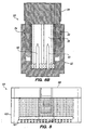
Fig. 4 , thecap 28 is secured within thehousing cavity 24 by theteeth 34 latching to theridges 32. Thegel sealant 36 is therefore compressed between thecap 28 and theshelf 25. As thecap 28 is advanced into thecavity 24, theteeth 34 engage with subsequent latchingridges 32 and secure the cap in a lower position within thecavity 24, applying a greater pressure to thegel sealant 36. The downward force of the latching ridges and teeth, combined with the upward force of the compressedgel sealant 36, secures thecap 28 in thehousing 22. Variances in gel thickness can thus be accounted for without sacrificing the seal that is obtained within the connector. - Referring to
Figs. 6A and6B , a close up view of theconnector 20 is shown, and more particularly, illustrating howelectrical contacts 40 are inserted through theapertures 21 of thehousing 22. With thegel sealant 36 in place, theelectrical contacts 40 pierce thegel sealant 36 and extend into the aperture 30 (Fig. 6B ). Due to the physical properties of thegel sealant 36 an environmental seal is formed around theelectrical contacts 40 so that contaminants can not penetrate into the lower regions of thehousing 22. - The
cap 28 aligns with thehousing 22, and theapertures 21 align with theelectrical contacts 40 that extend into thecavity 24. The latchingteeth 34 engage the latchingridges 32 to form a ratcheting mechanism that secures thecap 28 within thehousing cavity 24 and exerts pressure on thegel sealant 36 such that a seal is maintained between the extendedelectrical contacts 40 and the lower portion of thehousing 22. When theelectrical contacts 40 extend through theapertures 30, a female type connection device is formed, providing a receptacle for a complementary connector to be attached. -
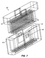
Figs. 7 and8 show an alternate embodiment of asealable connector 60 that includes acap 68 and ahousing 62. Thecap 68 includes latchingteeth 64 that engage with latchingridges 66 when the cap is inserted into thehousing 62. Agel sealant 70 is placed on a lower surface of the housing and forms a seal when thecap 68 is inserted into thehousing 62. - Although the invention has been described and illustrated in the above description and drawings, it is understood that this description is by example only and that numerous changes and modifications can be made by those skilled in the art without departing from the scope of the invention. The invention, therefore, is not to be restricted, except by the following claims.
Claims (9)
- A sealable connector (20), comprising:a first connector portion (22);a second connector portion (28) adapted to engage the first connector portion;a compliant material disposed between the first and second connectorportions; anda fastening mechanism (32, 34) that secures the first connector portion to the second connector portion,characterised in that:the compliant material comprises a gel sealant (36), and the fastening mechanism is adjustable and includes means for adjusting a force when said force is applied upon the gel sealant by the respective first and second connector portions.
- The connector of claim 1, wherein the first connector portion comprises a cup shaped body that defines a cavity (24), the body having a bottom surface (27).
- The connector of claim 1 or 2, wherein the second connector portion comprises a cap (28) adapted to fit at least partially within the body cavity.
- The connector of claim 2 or 3, further comprising a contact member extending from the body bottom surface, and a through hole or aperture (30) in the cap, wherein the contact member aligns with the through hole or aperture when the cap engages the body.
- The connector of any of the preceding claims, wherein the fastening mechanism comprises a ratchet or a spring biased member.
- The connector of any of the preceding claims, wherein the fastening mechanism comprises a latch, the latch comprising a tooth (34) on one of the first or second connector portions, the fastening mechanism further comprising a groove (32) on the other of the first or second connector portions, wherein the tooth is adapted to engage the groove.
- The connector of any of the preceding claims, wherein the first and second connector portions, when engaged, form a connection device adapted to mate with a complementary connector.
- The connector of any of the preceding claims, wherein the gel sealant forms an environmental seal between the first and second connector portions, when the respective connector portions are engaged.
- The connector of any of the preceding claims, wherein the force is a consistent pressure maintained on the gel sealant such that the gel sealant maintains a seal between the first and second connector portions.
Applications Claiming Priority (3)
| Application Number | Priority Date | Filing Date | Title |
|---|---|---|---|
| US25768100P | 2000-12-21 | 2000-12-21 | |
| US257681P | 2000-12-21 | ||
| PCT/US2001/050410 WO2002050957A1 (en) | 2000-12-21 | 2001-12-20 | Sealable connector |
Publications (2)
| Publication Number | Publication Date |
|---|---|
| EP1344283A1 EP1344283A1 (en) | 2003-09-17 |
| EP1344283B1 true EP1344283B1 (en) | 2008-02-13 |
Family
ID=22977297
Family Applications (1)
| Application Number | Title | Priority Date | Filing Date |
|---|---|---|---|
| EP01991555A Expired - Lifetime EP1344283B1 (en) | 2000-12-21 | 2001-12-20 | Sealable connector |
Country Status (7)
| Country | Link |
|---|---|
| US (1) | US6866529B2 (en) |
| EP (1) | EP1344283B1 (en) |
| JP (1) | JP2004521443A (en) |
| KR (1) | KR20030063447A (en) |
| AT (1) | ATE386352T1 (en) |
| DE (1) | DE60132810T2 (en) |
| WO (1) | WO2002050957A1 (en) |
Cited By (1)
| Publication number | Priority date | Publication date | Assignee | Title |
|---|---|---|---|---|
| CN112335133A (en) * | 2018-06-12 | 2021-02-05 | 泰连德国有限公司 | Method for producing an electrical connector, in particular for high-density base systems; and electrical connectors, in particular for the automotive industry; and high density pedestal system |
Families Citing this family (16)
| Publication number | Priority date | Publication date | Assignee | Title |
|---|---|---|---|---|
| US20030226978A1 (en) * | 1998-01-30 | 2003-12-11 | Segan Industries | Integrating ultraviolet exposure detection devices |
| US6875054B2 (en) * | 2002-07-05 | 2005-04-05 | Tyco Electronics Power Systems Inc. | Contamination prevention between two electrical components |
| ES2268484T3 (en) * | 2002-12-20 | 2007-03-16 | Tyco Electronics Corporation | ASSEMBLY OF THE COLLECTOR BAR. |
| US6854996B2 (en) * | 2002-12-20 | 2005-02-15 | Tyco Electronics Corporation | Electrical connectors and methods for using the same |
| US7056151B2 (en) * | 2003-02-18 | 2006-06-06 | Homac Mfg. Company | Connector and insulating boot for different sized conductors and associated methods |
| JP4565337B2 (en) | 2005-11-24 | 2010-10-20 | 住友電装株式会社 | connector |
| US7201596B1 (en) | 2006-01-06 | 2007-04-10 | Tyco Electronics Corporation | Electrical connector systems, plug systems and methods for using the same |
| US7465192B2 (en) * | 2006-09-11 | 2008-12-16 | J.S.T. Corporation | In-line sealed electrical connector apparatus |
| US7736187B2 (en) * | 2007-03-20 | 2010-06-15 | Tyco Electronics Corporation | Electrical connector assemblies and joint assemblies and methods for using the same |
| US7736165B2 (en) * | 2007-07-16 | 2010-06-15 | Tyco Electronics Corporation | Electrical connector assemblies and methods for forming and using the same |
| CN104979691B (en) * | 2015-06-04 | 2017-09-05 | 凡甲电子(苏州)有限公司 | Electric connector |
| DE102016215641B4 (en) * | 2016-08-19 | 2025-08-07 | Robert Bosch Gmbh | Connector for an electrical connection and method for producing a connector |
| EP3322042B1 (en) * | 2016-11-15 | 2020-03-18 | Aptiv Technologies Limited | Header connector comprising an interior undercut space |
| US10734769B2 (en) | 2017-07-19 | 2020-08-04 | Western Technology, Inc. | Safety electrical power connector |
| US11271384B2 (en) | 2017-07-27 | 2022-03-08 | Western Technology, Inc. | Power supply interlock |
| USD1002553S1 (en) * | 2021-11-03 | 2023-10-24 | Amphenol Corporation | Gasket for connector |
Family Cites Families (22)
| Publication number | Priority date | Publication date | Assignee | Title |
|---|---|---|---|---|
| US3678447A (en) * | 1970-06-17 | 1972-07-18 | Amp Inc | Coaxial cable connector sub-assembly |
| DE2317700A1 (en) * | 1973-04-09 | 1974-10-24 | Norddeutsche Seekabelwerke Ag | PRESSURE WATERPROOF CONNECTION FOR ELECTRIC CABLES |
| US4090759A (en) * | 1975-04-17 | 1978-05-23 | Amp Incorporated | Micro-miniature circular high voltage connector |
| US4864725A (en) | 1982-10-12 | 1989-09-12 | Raychem Corporation | Electrical connector and method of splicing wires |
| US4600261A (en) | 1982-10-12 | 1986-07-15 | Raychem Corporation | Apparatus and method for protection of electrical contacts |
| US4865905A (en) | 1983-06-23 | 1989-09-12 | Raychem Corporation | Article for protection of a substrate |
| US4690831A (en) | 1983-06-23 | 1987-09-01 | Raychem Corp. | Protective article |
| ZA856662B (en) | 1984-08-31 | 1987-05-27 | Raychem Corp | Heat stable polymeric gelloids |
| US4777063A (en) | 1985-05-02 | 1988-10-11 | Raychem Corporation | Curable organopolysiloxane composition |
| US4595635A (en) | 1985-05-02 | 1986-06-17 | Raychem Corporation | Organopolysiloxane materials having decreased surface tack |
| US4645285A (en) | 1985-08-26 | 1987-02-24 | Amp Incorporated | Sealed insulation displacement connector |
| US4716183A (en) | 1985-11-22 | 1987-12-29 | Raychem Corp. | Styrene-diene block copolymer compositions |
| GB8617559D0 (en) | 1986-07-18 | 1986-08-28 | Raychem Ltd | Gels |
| US4810208A (en) * | 1987-05-22 | 1989-03-07 | Amp Incorporated | Probeable sealed connector |
| US4852646A (en) | 1987-06-16 | 1989-08-01 | Raychem Corporation | Thermally conductive gel materials |
| JPH04503825A (en) | 1989-03-01 | 1992-07-09 | レイケム・コーポレイション | Method for curing organopolysiloxane compositions and articles made therefrom |
| JP2503322B2 (en) * | 1991-04-30 | 1996-06-05 | 矢崎総業株式会社 | Waterproof connector |
| US5588856A (en) | 1991-09-18 | 1996-12-31 | Raychem Corporation | Sealing member and methods of sealing |
| US5529508A (en) | 1994-04-01 | 1996-06-25 | Raychem Corporation | Sealing member |
| US5934922A (en) | 1997-02-07 | 1999-08-10 | Raychem Corporation | Sealing member |
| JP3437099B2 (en) | 1998-07-23 | 2003-08-18 | 矢崎総業株式会社 | Connector structure |
| JP2001266998A (en) * | 2000-03-16 | 2001-09-28 | Yazaki Corp | Waterproof connector |
-
2001
- 2001-12-20 EP EP01991555A patent/EP1344283B1/en not_active Expired - Lifetime
- 2001-12-20 US US10/032,324 patent/US6866529B2/en not_active Expired - Lifetime
- 2001-12-20 JP JP2002551951A patent/JP2004521443A/en active Pending
- 2001-12-20 KR KR10-2003-7008312A patent/KR20030063447A/en not_active Ceased
- 2001-12-20 WO PCT/US2001/050410 patent/WO2002050957A1/en not_active Ceased
- 2001-12-20 DE DE60132810T patent/DE60132810T2/en not_active Expired - Lifetime
- 2001-12-20 AT AT01991555T patent/ATE386352T1/en not_active IP Right Cessation
Cited By (2)
| Publication number | Priority date | Publication date | Assignee | Title |
|---|---|---|---|---|
| CN112335133A (en) * | 2018-06-12 | 2021-02-05 | 泰连德国有限公司 | Method for producing an electrical connector, in particular for high-density base systems; and electrical connectors, in particular for the automotive industry; and high density pedestal system |
| US12155145B2 (en) | 2018-06-12 | 2024-11-26 | Te Connectivity Germany Gmbh | Method for producing an electrical connector, in particular an electrical connector for a high-density header system; as well as an electrical connector, in particular an electrical connector for the motor vehicle industry; as well as high-density header system |
Also Published As
| Publication number | Publication date |
|---|---|
| ATE386352T1 (en) | 2008-03-15 |
| DE60132810T2 (en) | 2009-02-05 |
| JP2004521443A (en) | 2004-07-15 |
| US20020102874A1 (en) | 2002-08-01 |
| US6866529B2 (en) | 2005-03-15 |
| KR20030063447A (en) | 2003-07-28 |
| WO2002050957A1 (en) | 2002-06-27 |
| EP1344283A1 (en) | 2003-09-17 |
| DE60132810D1 (en) | 2008-03-27 |
Similar Documents
| Publication | Publication Date | Title |
|---|---|---|
| US6866529B2 (en) | Adjustable sealable connector | |
| US5529508A (en) | Sealing member | |
| US5588856A (en) | Sealing member and methods of sealing | |
| CA1292046C (en) | Article for protecting a substrate | |
| HUT72243A (en) | Electrical connecting block | |
| US10050372B2 (en) | Sealing insert for electrical connectors | |
| US6475029B2 (en) | Sealant-filled electrical connector and method for forming the same | |
| US5562491A (en) | Gel filled electrical connector | |
| JP4792583B2 (en) | Flat cable connector for sealing applications | |
| US20100167581A1 (en) | Waterproof Push-In Wire Connectors | |
| US4741709A (en) | Gel filled enclosure | |
| EP0549734B1 (en) | Sealing member and methods of sealing | |
| US5934922A (en) | Sealing member | |
| DE112006000556T5 (en) | transducers | |
| US6123336A (en) | Sealing device and method of sealing | |
| MXPA96004502A (en) | Member sella | |
| CA2314812A1 (en) | Non-silicone sealant for universal indoor-outdoor applications and insulation-displacement cross connector |
Legal Events
| Date | Code | Title | Description |
|---|---|---|---|
| PUAI | Public reference made under article 153(3) epc to a published international application that has entered the european phase |
Free format text: ORIGINAL CODE: 0009012 |
|
| 17P | Request for examination filed |
Effective date: 20030616 |
|
| AK | Designated contracting states |
Kind code of ref document: A1 Designated state(s): AT BE CH CY DE DK ES FI FR GB GR IE IT LI LU MC NL PT SE TR |
|
| 17Q | First examination report despatched |
Effective date: 20060831 |
|
| GRAP | Despatch of communication of intention to grant a patent |
Free format text: ORIGINAL CODE: EPIDOSNIGR1 |
|
| GRAS | Grant fee paid |
Free format text: ORIGINAL CODE: EPIDOSNIGR3 |
|
| GRAA | (expected) grant |
Free format text: ORIGINAL CODE: 0009210 |
|
| AK | Designated contracting states |
Kind code of ref document: B1 Designated state(s): AT BE CH CY DE DK ES FI FR GB GR IE IT LI LU MC NL PT SE TR |
|
| REG | Reference to a national code |
Ref country code: GB Ref legal event code: FG4D |
|
| REG | Reference to a national code |
Ref country code: CH Ref legal event code: EP |
|
| REG | Reference to a national code |
Ref country code: IE Ref legal event code: FG4D |
|
| REF | Corresponds to: |
Ref document number: 60132810 Country of ref document: DE Date of ref document: 20080327 Kind code of ref document: P |
|
| PG25 | Lapsed in a contracting state [announced via postgrant information from national office to epo] |
Ref country code: ES Free format text: LAPSE BECAUSE OF FAILURE TO SUBMIT A TRANSLATION OF THE DESCRIPTION OR TO PAY THE FEE WITHIN THE PRESCRIBED TIME-LIMIT Effective date: 20080524 Ref country code: FI Free format text: LAPSE BECAUSE OF FAILURE TO SUBMIT A TRANSLATION OF THE DESCRIPTION OR TO PAY THE FEE WITHIN THE PRESCRIBED TIME-LIMIT Effective date: 20080213 |
|
| NLV1 | Nl: lapsed or annulled due to failure to fulfill the requirements of art. 29p and 29m of the patents act | ||
| PG25 | Lapsed in a contracting state [announced via postgrant information from national office to epo] |
Ref country code: AT Free format text: LAPSE BECAUSE OF FAILURE TO SUBMIT A TRANSLATION OF THE DESCRIPTION OR TO PAY THE FEE WITHIN THE PRESCRIBED TIME-LIMIT Effective date: 20080213 |
|
| ET | Fr: translation filed | ||
| PG25 | Lapsed in a contracting state [announced via postgrant information from national office to epo] |
Ref country code: BE Free format text: LAPSE BECAUSE OF FAILURE TO SUBMIT A TRANSLATION OF THE DESCRIPTION OR TO PAY THE FEE WITHIN THE PRESCRIBED TIME-LIMIT Effective date: 20080213 |
|
| PG25 | Lapsed in a contracting state [announced via postgrant information from national office to epo] |
Ref country code: PT Free format text: LAPSE BECAUSE OF FAILURE TO SUBMIT A TRANSLATION OF THE DESCRIPTION OR TO PAY THE FEE WITHIN THE PRESCRIBED TIME-LIMIT Effective date: 20080714 Ref country code: SE Free format text: LAPSE BECAUSE OF FAILURE TO SUBMIT A TRANSLATION OF THE DESCRIPTION OR TO PAY THE FEE WITHIN THE PRESCRIBED TIME-LIMIT Effective date: 20080513 Ref country code: NL Free format text: LAPSE BECAUSE OF FAILURE TO SUBMIT A TRANSLATION OF THE DESCRIPTION OR TO PAY THE FEE WITHIN THE PRESCRIBED TIME-LIMIT Effective date: 20080213 Ref country code: DK Free format text: LAPSE BECAUSE OF FAILURE TO SUBMIT A TRANSLATION OF THE DESCRIPTION OR TO PAY THE FEE WITHIN THE PRESCRIBED TIME-LIMIT Effective date: 20080213 |
|
| PLBE | No opposition filed within time limit |
Free format text: ORIGINAL CODE: 0009261 |
|
| STAA | Information on the status of an ep patent application or granted ep patent |
Free format text: STATUS: NO OPPOSITION FILED WITHIN TIME LIMIT |
|
| 26N | No opposition filed |
Effective date: 20081114 |
|
| PG25 | Lapsed in a contracting state [announced via postgrant information from national office to epo] |
Ref country code: MC Free format text: LAPSE BECAUSE OF NON-PAYMENT OF DUE FEES Effective date: 20081231 Ref country code: CY Free format text: LAPSE BECAUSE OF FAILURE TO SUBMIT A TRANSLATION OF THE DESCRIPTION OR TO PAY THE FEE WITHIN THE PRESCRIBED TIME-LIMIT Effective date: 20080213 |
|
| REG | Reference to a national code |
Ref country code: CH Ref legal event code: PL |
|
| PG25 | Lapsed in a contracting state [announced via postgrant information from national office to epo] |
Ref country code: IT Free format text: LAPSE BECAUSE OF FAILURE TO SUBMIT A TRANSLATION OF THE DESCRIPTION OR TO PAY THE FEE WITHIN THE PRESCRIBED TIME-LIMIT Effective date: 20080213 |
|
| PG25 | Lapsed in a contracting state [announced via postgrant information from national office to epo] |
Ref country code: IE Free format text: LAPSE BECAUSE OF NON-PAYMENT OF DUE FEES Effective date: 20081222 Ref country code: CH Free format text: LAPSE BECAUSE OF NON-PAYMENT OF DUE FEES Effective date: 20081231 Ref country code: LI Free format text: LAPSE BECAUSE OF NON-PAYMENT OF DUE FEES Effective date: 20081231 |
|
| PG25 | Lapsed in a contracting state [announced via postgrant information from national office to epo] |
Ref country code: LU Free format text: LAPSE BECAUSE OF NON-PAYMENT OF DUE FEES Effective date: 20081220 |
|
| PG25 | Lapsed in a contracting state [announced via postgrant information from national office to epo] |
Ref country code: TR Free format text: LAPSE BECAUSE OF FAILURE TO SUBMIT A TRANSLATION OF THE DESCRIPTION OR TO PAY THE FEE WITHIN THE PRESCRIBED TIME-LIMIT Effective date: 20080213 |
|
| PG25 | Lapsed in a contracting state [announced via postgrant information from national office to epo] |
Ref country code: GR Free format text: LAPSE BECAUSE OF FAILURE TO SUBMIT A TRANSLATION OF THE DESCRIPTION OR TO PAY THE FEE WITHIN THE PRESCRIBED TIME-LIMIT Effective date: 20080514 |
|
| REG | Reference to a national code |
Ref country code: FR Ref legal event code: PLFP Year of fee payment: 15 |
|
| REG | Reference to a national code |
Ref country code: FR Ref legal event code: PLFP Year of fee payment: 16 |
|
| REG | Reference to a national code |
Ref country code: FR Ref legal event code: PLFP Year of fee payment: 17 |
|
| REG | Reference to a national code |
Ref country code: FR Ref legal event code: CD Owner name: TYCO ELECTRONICS CORPORATION, US Effective date: 20180626 |
|
| REG | Reference to a national code |
Ref country code: DE Ref legal event code: R082 Ref document number: 60132810 Country of ref document: DE Representative=s name: MARKS & CLERK (LUXEMBOURG) LLP, LU Ref country code: DE Ref legal event code: R081 Ref document number: 60132810 Country of ref document: DE Owner name: TE CONNECTIVITY CORPORATION, BERWYN, US Free format text: FORMER OWNER: TYCO ELECTRONICS CORP., MIDDLETOWN, PA., US |
|
| PGFP | Annual fee paid to national office [announced via postgrant information from national office to epo] |
Ref country code: GB Payment date: 20201210 Year of fee payment: 20 Ref country code: DE Payment date: 20201208 Year of fee payment: 20 Ref country code: FR Payment date: 20201112 Year of fee payment: 20 |
|
| REG | Reference to a national code |
Ref country code: DE Ref legal event code: R071 Ref document number: 60132810 Country of ref document: DE |
|
| REG | Reference to a national code |
Ref country code: GB Ref legal event code: PE20 Expiry date: 20211219 |
|
| PG25 | Lapsed in a contracting state [announced via postgrant information from national office to epo] |
Ref country code: GB Free format text: LAPSE BECAUSE OF EXPIRATION OF PROTECTION Effective date: 20211219 |