EP1344075B1 - Mesure vectorielle d'un champ magnetique - Google Patents
Mesure vectorielle d'un champ magnetique Download PDFInfo
- Publication number
- EP1344075B1 EP1344075B1 EP01978551A EP01978551A EP1344075B1 EP 1344075 B1 EP1344075 B1 EP 1344075B1 EP 01978551 A EP01978551 A EP 01978551A EP 01978551 A EP01978551 A EP 01978551A EP 1344075 B1 EP1344075 B1 EP 1344075B1
- Authority
- EP
- European Patent Office
- Prior art keywords
- components
- magnetic field
- frequency
- transfer function
- signal
- Prior art date
- Legal status (The legal status is an assumption and is not a legal conclusion. Google has not performed a legal analysis and makes no representation as to the accuracy of the status listed.)
- Expired - Lifetime
Links
- 239000013598 vector Substances 0.000 title abstract description 13
- 238000005259 measurement Methods 0.000 title description 9
- 238000012546 transfer Methods 0.000 claims abstract description 60
- 230000006870 function Effects 0.000 claims description 66
- 238000000034 method Methods 0.000 claims description 17
- 238000012545 processing Methods 0.000 claims description 16
- 230000001360 synchronised effect Effects 0.000 claims description 12
- 238000001514 detection method Methods 0.000 claims description 10
- 230000008569 process Effects 0.000 claims description 8
- 238000012937 correction Methods 0.000 claims description 6
- 230000001934 delay Effects 0.000 claims description 6
- 230000000737 periodic effect Effects 0.000 claims description 4
- 239000004020 conductor Substances 0.000 claims 4
- 238000000691 measurement method Methods 0.000 abstract description 2
- 238000004804 winding Methods 0.000 description 43
- 229910052734 helium Inorganic materials 0.000 description 5
- 239000001307 helium Substances 0.000 description 5
- SWQJXJOGLNCZEY-UHFFFAOYSA-N helium atom Chemical compound [He] SWQJXJOGLNCZEY-UHFFFAOYSA-N 0.000 description 5
- 230000008859 change Effects 0.000 description 4
- 238000005086 pumping Methods 0.000 description 3
- 230000001419 dependent effect Effects 0.000 description 2
- 230000003287 optical effect Effects 0.000 description 2
- 230000009466 transformation Effects 0.000 description 2
- 230000008901 benefit Effects 0.000 description 1
- 230000008878 coupling Effects 0.000 description 1
- 238000010168 coupling process Methods 0.000 description 1
- 238000005859 coupling reaction Methods 0.000 description 1
- 230000007547 defect Effects 0.000 description 1
- 238000011161 development Methods 0.000 description 1
- 230000018109 developmental process Effects 0.000 description 1
- 230000009977 dual effect Effects 0.000 description 1
- 230000005684 electric field Effects 0.000 description 1
- 230000004907 flux Effects 0.000 description 1
- 230000006872 improvement Effects 0.000 description 1
- 238000012423 maintenance Methods 0.000 description 1
- 230000010287 polarization Effects 0.000 description 1
- 230000001105 regulatory effect Effects 0.000 description 1
- 230000004044 response Effects 0.000 description 1
- 230000000717 retained effect Effects 0.000 description 1
- 239000000523 sample Substances 0.000 description 1
- 230000000638 stimulation Effects 0.000 description 1
Images


Classifications
-
- G—PHYSICS
- G01—MEASURING; TESTING
- G01R—MEASURING ELECTRIC VARIABLES; MEASURING MAGNETIC VARIABLES
- G01R33/00—Arrangements or instruments for measuring magnetic variables
- G01R33/20—Arrangements or instruments for measuring magnetic variables involving magnetic resonance
- G01R33/24—Arrangements or instruments for measuring magnetic variables involving magnetic resonance for measuring direction or magnitude of magnetic fields or magnetic flux
Definitions
- the present invention relates to a device and a method for measuring the components of a magnetic field using a scalar magnetometer. It finds an application in the measurement of weak magnetic fields (of the order of magnitude of the Earth's magnetic field, a few tens of microteslas) that we want to obtain with great precision, of the order of 10 -5 .
- a vector magnetometer using such scalar magnetometer and able to deliver the values of each of the components of the vector field magnetic module whose module is issued by the scalar magnetometer is described in the application for EP-A-0 964 260.
- a device capable of performing such a change of axes may include, in addition to means for calculating the axis change matrices, sensors dedicated to this function. The calculation can also be made from detections made by each of the other two coils of a field emitted by one of the coils.
- Figure 1 part A shows two curves.
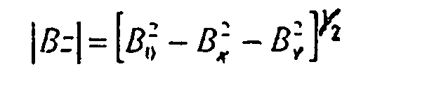
- a first curve marked a represents the evolution in the time of the value of the module of the vector field magnetic obtained from the scalar sensor.
- a second curve in solid lines marked b represents evolution at the same time of the value of this module calculated from its three components obtained by analyzing signals from each of the three windings.
- Figure 1 Part B represents on a scale enlarged for the ordinates, evolution in the same time difference dB between the values of the modules obtained by direct measurement and by calculation.
- the invention therefore relates to a device and a method for measuring the components of a magnetic field to 10 -5 .
- the reason for this assumption is as follows.
- the operation in vector mode is based on the analysis of the scalar magnetometer response to periodic mode stimulation at each of the frequencies Fx, Fy, and possibly Fz.
- any change in bandwidth of the scalar magnetometer will affect the previously determined transfer functions, in a way that is no longer negligible when looking for an accuracy of the order of 10 -5 .
- the bandwidth is a resultant of the different physical phenomena implemented in the scalar probe.
- a scalar magnetometer with helium optical pumping according to the document FR-A-2 713 347 already mentioned (or its American correspondent US-A-5,534,776), it depends in particular on the relaxation time of the atoms in the metastable level which varies with the temperature T proportionally to 1 / T and with the intensity of the high frequency electric field for the maintenance of the discharge, the pumping time which depends on the intensity of the laser beam, or else the characteristic time constant of the magnetic resonance which is a function of the radiofrequency field .
- the instrumental instrumental function which depends on the known characteristics of the instrument is known to within 10 -5 . It remains according to the invention to determine for each frequency Fx, or Fy or Fz the transfer function H (F).
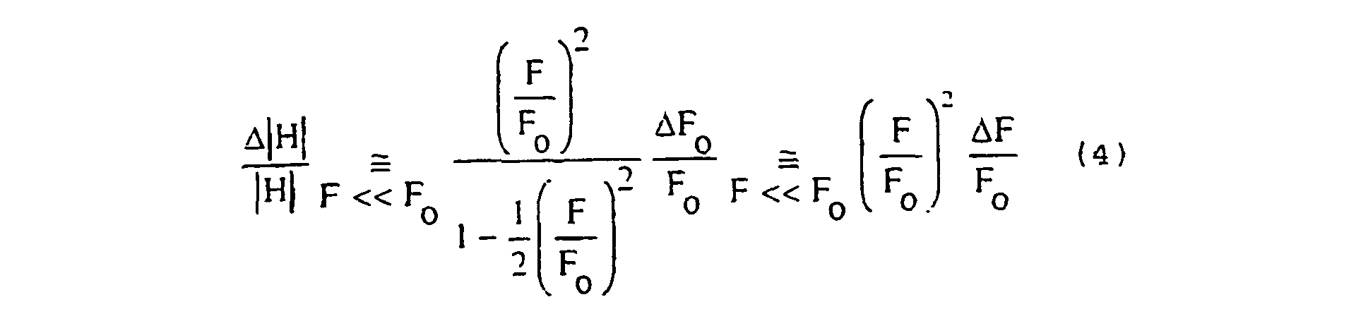
- the module In the case of a small frequency in front of the cutoff frequency of this filter, the module is developed in the second order: hence a relative fluctuation proportional to the relative fluctuations of F o :
- the fluctuations of the transfer functions are therefore proportional to those of the bandwidth of the helium scalar sensor, the proportionality factor depending on F 2 .
- the scalar residual then varies proportionally with the fluctuation of the bandwidth:
- phase of this filter is given by the expression:
- the proposed method is to take into account fluctuations in the bandwidth of the magnetometer scalar by exploiting the information contained in the phases of the signals generated by one or more of the modulations.
- phase measurement makes it possible to estimate the cut-off frequency F 0 of the magnetometer, which is then used to correct the modulus of the transfer function
- a device for measuring the components of the magnetic field will include all the elements described in relation to patent application FR 98 07 216 already cited, but one at least means for applying to at least one of the Ex, Ey, and Ez windings, a first signal will be modified to generate a second signal at the same frequency but out of phase with the other.
- the first signal will be as in the applied prior art to windings Ex, Ey, and Ez.
- the detection means associated with each of the windings will be able to perform not only the phase detection as in the prior art, but also according to the invention, a detection in quadrature. To this end they will receive the second signals out of phase with the first signals.
- the means of calculation will include, in accordance with the invention of the means for calculating the phase of the transfer function of the scalar magnetometer for at less one of the frequencies applied to a winding, and the module of this function.
- Software means of treatment will be modified to perform a double synchronous demodulation, in phase and in quadrature, on at least one of the specific frequencies of each axis and calculate a correction of the value of the continuous component according to each of the axes taking account the results of this double demodulation.
- each axis there is one winding for each axis, and three generators G x , G y , G z . These three generators are each equipped with a quarter-wave delay. Each of the three generators is coupled to a winding and a demodulator performing in-phase demodulation. Each of the delays is coupled to a demodulator performing quadrature demodulation.
- the invention also relates to a method for measuring components of a magnetic field along axes (Ox, Oy, Oz), oriented in different directions, obtained from a device using a scalar magnetometer delivering a corresponding output signal.
- the module B 0 of an applied magnetic field the method of superimposing on the magnetic field to be measured fields each oriented along each of the axes (Ox, Oy, Oz) respectively, these superposed fields varying in time periodically according to a frequency (Fx, Fy, Fz) specific to each axis, then synchronously demodulating at each of the frequencies (Fx, Fy, Fz) the signal from the scalar magnetometer and processing the signal resulting from a synchronous demodulation to a frequency, to deduce the value of the DC component of the magnetic field along the axis receiving the field superimposed on this frequency, characterized in that for at least one In the axial directions, the demodulation is performed synchronously in phase and in quadrature for at least one of the superposed fields and
- cutoff frequencies transfer functions are between 200 and 1,000 hertz and in general around 400 hertz while the frequencies of the overlay fields are chosen between 5 and 60 hertz so that the values these frequencies are always small compared to cutoff frequencies.
- the transfer functions at different modulation frequencies can be calculate from one of them. It is why, when demodulation data at a frequency are noisy, we will be interested in calculating a transfer function for this noisy frequency to from a transfer function obtained for a different frequency in which the signal ratio on noise is high.
- This magnetometer 2 comprises in a known manner a cell 10 filled with helium, a laser 14 emitting a beam 15, a polarizer 16 delivering a beam polarized rectilinear 17, a photodetector 24 receiving the beam 18 having passed through the cell 10, a circuit frequency servo-control 21, a generator of radio frequency 22, a frequency meter 26 and a circuit 30.
- the generator 22 supplies power a coil 56 placed near the cell 10 of to generate in the latter a field of radio frequency.
- the coil 56 and the polarizer 16 are mechanically linked so that any rotation applied to the polarizer causes a rotation the same angle of the direction of the field, the intensity of the latter being defined by the generator 22.
- a rotating contact is used, for example a contact by capacitive coupling or by a transformer whose the primary winding is fixed and the winding secondary mobile.
- the coil 10 and the polarizer 16 are mounted so that the polarization and the applied field are parallel.
- the circuit 40 is a servo circuit which controls a motor 46 regulating the angular position of the polarizer 16. This circuit is described in the document city.
- the device comprises three conductive windings Ex, Ey and Ez, the axes of which form a trihedral Oxyz. For greater clarity, these windings are shown spaced apart from the cell 10, but it should be understood that these windings surround the cell 10.
- Each of the windings Ex, Ey, Ez is connected to a generator, respectively Gx, Gy and Gz, each set on a particular modulation frequency F x , F y , F z .
- the modulation frequencies F x , F y , F z are of course different from one another.
- each generator Gx, Gy and Gz is equipped with a quarter-wave delay, 31, 32, 33 respectively.
- a processing circuit 70 comprises six Dx D, Dy D', Dz D'z coupled demodulators respectively to generators Gx, Gy, Gz and quarter wave delays 31, 32, 33 and receiving the signal output from the scalar magnetometer, i.e., in the illustrated embodiment, the signal delivered by the frequency meter 26.
- This signal is, in general, a digital signal giving the Bo module of field to measure.
- the application of an external field Hx applied on the along the Ox axis with a frequency Fx changes the module of the field to measure a quantity that varies at the frequency Fx.
- the output signal of the magnetometer scalar which gives the module of the field, therefore contains a component varying at frequency Fx, component representing the projection of the field to be measured on the axis Ox.
- the value of this projection also depends on explained above the value of the function of magnetometer transfer for this frequency. In demodulating in phase and in quadrature the signal of output of the scalar magnetometer at the frequency Fx, will access the value of this component and also to the value of the module and phase of the function of transfer. We can therefore calculate a corrected value of the component on Ox. Similarly for the other two components.
- the calculation module 34 incorporates a function change of axes to deliver values of each component of the field on a trihedron orthonormed calculated according to one of the described methods in the article by J. M. G. MERAYO, F. PRIMDAHL AND P. BRAUER already quoted.
- an axis of the orthonormal trihedron calculated is confused with one of the axes of the windings.
- the parameters of the matrices of transformation are calculated in a phase of prior calibration identical in principle to methods applied to flux gates (fluxgates in English terminology).
- the number of windings Ex, Ey, Ez can vary between two and three, as the number of quarter wave delays 31 32 33 may vary between one and three, it follows that the number of synchronous detectors can vary between 3 and 6. There are will have three if we have two generators of which only one equipped with a delay, and 6 for three generators equipped each one of a delay.
Landscapes
- Physics & Mathematics (AREA)
- Condensed Matter Physics & Semiconductors (AREA)
- General Physics & Mathematics (AREA)
- Measuring Magnetic Variables (AREA)
- Soft Magnetic Materials (AREA)
Description
- au moins deux enroulements conducteurs disposés autour dudit magnétomètre scalaire, ces enroulements conducteurs ayant des axes orientés dans des directions différentes (Ox, Oy, Oz),
- des moyens pour alimenter chaque enroulement par un courant ayant une fréquence déterminée (Fx, Fy, Fz) propre à cet enroulement,





- au moins deux enroulements conducteurs disposés autour dudit magnétomètre scalaire, ces enroulements conducteurs ayant des axes orientés dans des directions différentes (Ox, Oy, Oz),
- des moyens pour alimenter chaque enroulement par un courant ayant une fréquence déterminée (Fx, Fy, Fz) propre à cet enroulement,
- des moyens de traitement recevant le signal délivré par le magnétomètre scalaire, et traitant ce signal pour en déduire une valeur de la composante continue selon chacun des axes des enroulements,
- on calcule les composantes non corrigées du champ magnétique,
- on effectue une comparaison entre les composantes pour déterminer la plus grande,
- on effectue la correction en appliquant à chaque composante axiale la fonction de transfert correspondant à la fréquence de modulation appliquée à l'enroulement selon l'axe de cette composante axiale, la fonction de transfert de la composante la plus grande étant obtenue directement à partir des résultats de démodulation et la fonction de transfert des autres composantes étant obtenue de façon indirecte à partir de la fonction de transfert de la composante la plus grande.
Claims (10)
- Dispositif (1) de mesure précise des composantes d'un champ magnétique ayant :un magnétomètre (2) scalaire délivrant un signal de sortie correspondant au module d'un champ magnétique appliqué :dispositif caractérisé en ce que au moins l'un des moyens (Gx, Gy, Gz) pour alimenter chaque enroulement (Ex, Ey, Ez) par un courant ayant une fréquence déterminée (Fx, Fy, Fz) propre à cet enroulement, produit à cette fréquence des signaux en phase et en quadrature, en ce que les moyens de traitement (70) recevant le signal délivré par le magnétomètre (2) scalaire, comprennent des moyens de démodulation (Dx, D'x, Dy D'y, Dz D'z) aptes à effectuer outre une démodulation synchrone en phase au moins aux fréquences (Fx, Fy, Fz) d'alimentation des enroulements, une démodulation en quadrature pour au moins l'une des fréquences (Fx, Fy, Fz) des courants d'alimentation des enroulements (Ex, Ey, Ez), ces moyens de démodulation recevant outre le signal en phase généré par l'alimentation des enroulements (Ex, Ey, Ez) le signal en quadrature en provenance des moyens de génération (Gx, Gy, Gz) et enfin en ce que ces moyens de traitement (70) comprennent un module de calcul (34) calculant de façon directe ou indirecte à partir des résultats des différentes démodulations pour chaque fréquence, au moins une fonction de transfert du magnétomètre pour l'une des fréquences délivrées par les moyens pour alimenter chaque enroulement par un courant ayant une fréquence déterminée (Fx, Fy, Fz) propre à cet enroulement, et corrigeant la valeur du module de chaque composante par application de la fonction de transfert calculée de façon directe ou indirecte.au moins deux enroulements conducteurs (Ex, Ey, Ez) disposés autour dudit magnétomètre scalaire, ces enroulements conducteurs (Ex, Ey, Ez) ayant des axes orientés dans des directions différentes (Ox, Oy, Oz),des moyens pour alimenter chaque enroulement par un courant ayant une fréquence déterminée (Fx, Fy, Fz) propre à cet enroulement,des moyens de traitement (70) recevant le signal délivré par le magnétomètre (2) scalaire, et traitant ce signal pour en déduire une valeur de la composante continue selon chacun des axes des enroulements,
- Dispositif (1) de mesure précise des composantes d'un champ magnétique selon la revendication 1 dans lequel les axes (Ox, Oy, Oz) des enroulements conducteurs (Ex, Ey, Ez) forment un repère orthonormé ou proche d'un repère orthonormé.
- Dispositif (1) selon la revendication 2, comprenant trois enroulements conducteurs (Ex, Ey, Ez) à axes mutuellement orthogonaux (Ox, Oy, Oz).
- Dispositif (1) selon l'une des revendications 1 à 3 dans lequel des moyens de génération (Gx, Gy, Gz) pour alimenter chaque enroulement (Ex, Ey, Ez) par un courant ayant une fréquence déterminée (Fx, Fy, Fz) propre à cet enroulement sont équipés d'un retard quart d'onde (31-33) dont une sortie est couplée à un moyen de détection (D'x, D'y, D'z).
- Dispositif (1) selon l'une des revendications 1 à 4 dans lequel les moyens de traitement (70) comportent un nombre de moyens de détection synchrone égal à la somme du nombre de générateurs de signaux et du nombre de retards quart d'onde (31-33) équipant lesdits générateurs de signaux
- Procédé de mesure de composantes d'un champ magnétique selon des axes (Ox, Oy, Oz), orientés dans des directions différentes, obtenues à partir d'un dispositif utilisant un magnétomètre scalaire délivrant un signal de sortie correspondant au module B0 d'un champ magnétique appliqué, le procédé consistant à superposer au champ magnétique à mesurer des champs orientés chacun selon chacun des axes (Ox, Oy, Oz) respectivement, ces champs variant dans le temps de façon périodique selon une fréquence (Fx, Fy, Fz) spécifique à chaque axe, puis à démoduler de façon synchrone à chacune des fréquences (Fx, Fy, Fz) le signal issu du magnétomètre et à traiter le signal résultant d'une démodulation synchrone à une fréquence pour en déduire la valeur de la composante continue du champ magnétique selon l'axe recevant le champ superposé à cette fréquence, procédé caractérisé en ce que pour l'une au moins des directions axiales, la démodulation est effectuée de façon synchrone en phase et en quadrature pour l'un au moins des champs superposés et en ce que on calcule directement à partir des résultats de démodulation au moins une fonction de transfert du magnétomètre pour l'une des fréquences à laquelle on a effectué une superposition d'un champ périodique à cette fréquence, et éventuellement de façon indirecte une ou deux fonctions de transfert à partir d'une fonction de transfert obtenue directement et en ce que l'on corrige la valeur du module de chaque composante par application de l'une des fonctions de transfert calculées de façon directe ou indirecte.
- Procédé de mesure de composantes d'un champ magnétique selon la revendication 6 dans lequel on calcule directement à partir des résultats de la démodulation en phase et en quadrature une fonction de transfert par fréquence de modulation et dans lequel on applique la fonction de transfert calculée pour chacune des fréquences de modulation respectivement à la correction de la composante du champ magnétique correspondant à cette fréquence de modulation.
- Procédé de mesure de composantes d'un champ magnétique selon la revendication 6 dans lequel :on calcule les composantes non corrigées du champ magnétique,on effectue une comparaison entre les composantes pour déterminer la plus grande,on effectue la correction en appliquant à chaque composante axiale la fonction de transfert correspondant à la fréquence de modulation appliquée à l'enroulement selon l'axe de cette composante axiale, la fonction de transfert de la composante la plus grande étant obtenue directement à partir des résultats de démodulation et la fonction de transfert des autres composantes étant obtenue de façon indirecte à partir de la fonction de transfert de la composante la plus grande.
- Procédé de mesure de composantes d'un champ magnétique selon la revendication 6 dans lequel :on calcule les composantes non corrigées du champ magnétique,on compare la valeur de chacune des composantes à une valeur seuilon effectue une comparaison entre les composantes pour déterminer la plus grande,ensuite on corrige chacune des composantes supérieures au seuil en lui appliquant la fonction de transfert correspondant à la fréquence relative à cette composante obtenue de façon directe, et on corrige les composantes inférieures au seuil en leur appliquant une fonction de transfert obtenue de façon indirecte à partir de la fonction de transfert correspondant à la plus grande des composantes.
- Procédé de mesure de composantes d'un champ magnétique selon l'une des revendications 6 à 9 dans lequel on recalcule les composantes du champ magnétique à partir des composantes axiales corrigées dans un système d'axes fictifs exactement orthonormé, l'un des axes fictifs coïncidant avec l'un des axes des enroulements.
Applications Claiming Priority (3)
| Application Number | Priority Date | Filing Date | Title |
|---|---|---|---|
| FR0013328A FR2815416B1 (fr) | 2000-10-18 | 2000-10-18 | Mesure vectorielle amelioree d'un champ magnetique |
| FR0013328 | 2000-10-18 | ||
| PCT/FR2001/003212 WO2002033434A1 (fr) | 2000-10-18 | 2001-10-17 | Mesure vectorelle d'un champ magnetique |
Publications (2)
| Publication Number | Publication Date |
|---|---|
| EP1344075A1 EP1344075A1 (fr) | 2003-09-17 |
| EP1344075B1 true EP1344075B1 (fr) | 2005-08-31 |
Family
ID=8855464
Family Applications (1)
| Application Number | Title | Priority Date | Filing Date |
|---|---|---|---|
| EP01978551A Expired - Lifetime EP1344075B1 (fr) | 2000-10-18 | 2001-10-17 | Mesure vectorielle d'un champ magnetique |
Country Status (6)
| Country | Link |
|---|---|
| US (1) | US6844726B2 (fr) |
| EP (1) | EP1344075B1 (fr) |
| AT (1) | ATE303603T1 (fr) |
| DE (1) | DE60113151T2 (fr) |
| FR (1) | FR2815416B1 (fr) |
| WO (1) | WO2002033434A1 (fr) |
Cited By (1)
| Publication number | Priority date | Publication date | Assignee | Title |
|---|---|---|---|---|
| EP2541268A1 (fr) | 2011-07-01 | 2013-01-02 | Commissariat à l'Énergie Atomique et aux Énergies Alternatives | Magnétomètre vectoriel à haute résolution et de haute précision |
Families Citing this family (5)
| Publication number | Priority date | Publication date | Assignee | Title |
|---|---|---|---|---|
| WO2012172435A2 (fr) * | 2011-05-13 | 2012-12-20 | Rampart Detection Systems Ltd. | Gradiomètre électromagnétique transversal |
| US9645205B2 (en) | 2012-12-11 | 2017-05-09 | Northrop Grumman Guidance And Electronics Company, Inc. | Combined electron paramagnetic resonance (EPR) and nuclear magnetic resonance (NMR) magnetometer system |
| US9739847B1 (en) * | 2016-02-01 | 2017-08-22 | Allegro Microsystems, Llc | Circular vertical hall (CVH) sensing element with signal processing |
| US10481220B2 (en) | 2016-02-01 | 2019-11-19 | Allegro Microsystems, Llc | Circular vertical hall (CVH) sensing element with signal processing and arctangent function |
| US9739848B1 (en) * | 2016-02-01 | 2017-08-22 | Allegro Microsystems, Llc | Circular vertical hall (CVH) sensing element with sliding integration |
Family Cites Families (11)
| Publication number | Priority date | Publication date | Assignee | Title |
|---|---|---|---|---|
| FR1354208A (fr) * | 1963-01-22 | 1964-03-06 | Csf | Nouveau magnétomètre à pompage optique |
| US3828243A (en) * | 1968-05-01 | 1974-08-06 | Varian Associates | Apparatus and method for electromagnetic geophysical exploration |
| GB1402257A (en) * | 1971-10-04 | 1975-08-06 | Nat Res Dev | Vector magnetometer |
| FR2663431B1 (fr) * | 1990-06-14 | 1992-09-11 | Commissariat Energie Atomique | Magnetometre a resonance magnetique et a enroulements d'excitation multiplexes. |
| FR2663751B1 (fr) * | 1990-06-25 | 1992-09-18 | Commissariat Energie Atomique | Magnetometre directionnel a resonance. |
| US5239474A (en) * | 1990-11-20 | 1993-08-24 | Hughes Aircraft Company | Dipole moment detection and localization |
| FR2713347B1 (fr) * | 1993-12-01 | 1995-12-29 | Commissariat Energie Atomique | Magnétomètre à polarisation lumineuse et à champ de radiofréquence couplés. |
| FR2779530B1 (fr) * | 1998-06-09 | 2000-07-07 | Commissariat Energie Atomique | Dispositif de mesure des composantes d'un champ magnetique a l'aide d'un magnetometre scalaire |
| US6476610B1 (en) * | 2001-04-24 | 2002-11-05 | The United States Of America As Represented By The Secretary Of The Navy | Magnetic anomaly sensing system and methods for maneuverable sensing platforms |
| US6714008B1 (en) * | 2002-07-29 | 2004-03-30 | The United States Of America As Represented By The Secretary Of The Navy | Gradiometric measurement methodology for determining magnetic fields of large objects |
| US6800913B2 (en) * | 2002-11-04 | 2004-10-05 | The United States Of America As Represented By The Secretary Of The Navy | Hybrid Hall vector magnetometer |
-
2000
- 2000-10-18 FR FR0013328A patent/FR2815416B1/fr not_active Expired - Fee Related
-
2001
- 2001-10-17 AT AT01978551T patent/ATE303603T1/de not_active IP Right Cessation
- 2001-10-17 DE DE60113151T patent/DE60113151T2/de not_active Expired - Lifetime
- 2001-10-17 WO PCT/FR2001/003212 patent/WO2002033434A1/fr not_active Ceased
- 2001-10-17 EP EP01978551A patent/EP1344075B1/fr not_active Expired - Lifetime
- 2001-10-17 US US10/399,256 patent/US6844726B2/en not_active Expired - Lifetime
Cited By (1)
| Publication number | Priority date | Publication date | Assignee | Title |
|---|---|---|---|---|
| EP2541268A1 (fr) | 2011-07-01 | 2013-01-02 | Commissariat à l'Énergie Atomique et aux Énergies Alternatives | Magnétomètre vectoriel à haute résolution et de haute précision |
Also Published As
| Publication number | Publication date |
|---|---|
| WO2002033434A1 (fr) | 2002-04-25 |
| ATE303603T1 (de) | 2005-09-15 |
| US6844726B2 (en) | 2005-01-18 |
| DE60113151D1 (de) | 2005-10-06 |
| FR2815416A1 (fr) | 2002-04-19 |
| US20040046553A1 (en) | 2004-03-11 |
| FR2815416B1 (fr) | 2002-12-13 |
| EP1344075A1 (fr) | 2003-09-17 |
| DE60113151T2 (de) | 2006-07-06 |
Similar Documents
| Publication | Publication Date | Title |
|---|---|---|
| EP2426563B1 (fr) | Procédé de calibration d'un appareil à fonctionnement atomique | |
| EP3524990A1 (fr) | Magnétomètre vectoriel à polarisation elliptique | |
| EP0462000A1 (fr) | Magnétomètre à résonance et à pompage optique utilisant une pluralite de faisceaux multiplexes | |
| EP1272805B1 (fr) | Procede et dispositif magnetique de determination de l'orientation | |
| EP3454139B1 (fr) | Système de mesure optique à asservissement davll stabilisé et procédé associé | |
| EP3598157A1 (fr) | Magnétomètre vectoriel en alignement à deux faisceaux de sonde polarisés différemment | |
| EP3436779A1 (fr) | Dispositif de mesure de rotation, procede et centrale de navigation inertielle associes | |
| EP0656545B1 (fr) | Magnétomètre à polarisation lumineuse et à champ de radiofréquence couplés | |
| EP0579537B1 (fr) | Magnétomètre à polarisation lumineuse et à champ de radio-fréquence asservis | |
| EP2541268B1 (fr) | Magnétomètre vectoriel à haute résolution et de haute précision | |
| EP1344075A1 (fr) | Mesure vectorielle d'un champ magnetique | |
| EP0964260A1 (fr) | Dispositif de mesure des composantes d'un champ magnétique à l'aide d'un magnétomètre scalaire | |
| EP0461999B1 (fr) | Magnétomètre à résonance et à pompage optique utilisant un faisceau lumineux à polarisation asservie | |
| EP3299831B1 (fr) | Réseau de magnétomètres vectoriels et procédé associé de calibration des couplages entre magnétomètres | |
| EP4343281A1 (fr) | Procede de mesure d'une vitesse angulaire de rotation et/ou d'une position angulaire | |
| EP4075156A1 (fr) | Procédé d exploitation d'un magnétomètre a pompage optique champ nul opéré dans un champ ambiant non nul | |
| EP0614091A1 (fr) | Magnétomètre différentiel à résonance | |
| EP0296005A1 (fr) | Magnétomètre à résonance magnétique nucléaire | |
| EP3654048A1 (fr) | Magnétomètre en alignement à décalage angulaire entre polarisations des faisceaux de pompe et de sonde | |
| EP0886148A1 (fr) | Procédés et systèmes de localisation radiosatellitaire en temps réel, notamment de type GPS | |
| FR3160460A1 (fr) | Procédé de mesure et capteur gyroscopiques | |
| EP0616227A1 (fr) | Magnomètre directionnel à résonance de type numérique | |
| WO2025027005A1 (fr) | Determination de pose par mesure d'un champ magnetique oscillant produit par des generateurs non orthogonaux |
Legal Events
| Date | Code | Title | Description |
|---|---|---|---|
| PUAI | Public reference made under article 153(3) epc to a published international application that has entered the european phase |
Free format text: ORIGINAL CODE: 0009012 |
|
| 17P | Request for examination filed |
Effective date: 20030404 |
|
| AK | Designated contracting states |
Kind code of ref document: A1 Designated state(s): AT BE CH CY DE DK ES FI FR GB GR IE IT LI LU MC NL PT SE TR |
|
| 17Q | First examination report despatched |
Effective date: 20040601 |
|
| GRAP | Despatch of communication of intention to grant a patent |
Free format text: ORIGINAL CODE: EPIDOSNIGR1 |
|
| GRAS | Grant fee paid |
Free format text: ORIGINAL CODE: EPIDOSNIGR3 |
|
| GRAA | (expected) grant |
Free format text: ORIGINAL CODE: 0009210 |
|
| AK | Designated contracting states |
Kind code of ref document: B1 Designated state(s): AT BE CH CY DE DK ES FI FR GB GR IE IT LI LU MC NL PT SE TR |
|
| PG25 | Lapsed in a contracting state [announced via postgrant information from national office to epo] |
Ref country code: IE Free format text: LAPSE BECAUSE OF FAILURE TO SUBMIT A TRANSLATION OF THE DESCRIPTION OR TO PAY THE FEE WITHIN THE PRESCRIBED TIME-LIMIT Effective date: 20050831 Ref country code: FI Free format text: LAPSE BECAUSE OF FAILURE TO SUBMIT A TRANSLATION OF THE DESCRIPTION OR TO PAY THE FEE WITHIN THE PRESCRIBED TIME-LIMIT Effective date: 20050831 Ref country code: TR Free format text: LAPSE BECAUSE OF FAILURE TO SUBMIT A TRANSLATION OF THE DESCRIPTION OR TO PAY THE FEE WITHIN THE PRESCRIBED TIME-LIMIT Effective date: 20050831 Ref country code: AT Free format text: LAPSE BECAUSE OF FAILURE TO SUBMIT A TRANSLATION OF THE DESCRIPTION OR TO PAY THE FEE WITHIN THE PRESCRIBED TIME-LIMIT Effective date: 20050831 Ref country code: NL Free format text: LAPSE BECAUSE OF FAILURE TO SUBMIT A TRANSLATION OF THE DESCRIPTION OR TO PAY THE FEE WITHIN THE PRESCRIBED TIME-LIMIT Effective date: 20050831 |
|
| REG | Reference to a national code |
Ref country code: GB Ref legal event code: FG4D Free format text: NOT ENGLISH Ref country code: CH Ref legal event code: EP |
|
| REG | Reference to a national code |
Ref country code: IE Ref legal event code: FG4D Free format text: LANGUAGE OF EP DOCUMENT: FRENCH |
|
| REF | Corresponds to: |
Ref document number: 60113151 Country of ref document: DE Date of ref document: 20051006 Kind code of ref document: P |
|
| PG25 | Lapsed in a contracting state [announced via postgrant information from national office to epo] |
Ref country code: CY Free format text: LAPSE BECAUSE OF FAILURE TO SUBMIT A TRANSLATION OF THE DESCRIPTION OR TO PAY THE FEE WITHIN THE PRESCRIBED TIME-LIMIT Effective date: 20051017 |
|
| PG25 | Lapsed in a contracting state [announced via postgrant information from national office to epo] |
Ref country code: LI Free format text: LAPSE BECAUSE OF NON-PAYMENT OF DUE FEES Effective date: 20051031 Ref country code: MC Free format text: LAPSE BECAUSE OF NON-PAYMENT OF DUE FEES Effective date: 20051031 Ref country code: CH Free format text: LAPSE BECAUSE OF NON-PAYMENT OF DUE FEES Effective date: 20051031 Ref country code: LU Free format text: LAPSE BECAUSE OF NON-PAYMENT OF DUE FEES Effective date: 20051031 Ref country code: BE Free format text: LAPSE BECAUSE OF NON-PAYMENT OF DUE FEES Effective date: 20051031 |
|
| PG25 | Lapsed in a contracting state [announced via postgrant information from national office to epo] |
Ref country code: SE Free format text: LAPSE BECAUSE OF FAILURE TO SUBMIT A TRANSLATION OF THE DESCRIPTION OR TO PAY THE FEE WITHIN THE PRESCRIBED TIME-LIMIT Effective date: 20051130 Ref country code: DK Free format text: LAPSE BECAUSE OF FAILURE TO SUBMIT A TRANSLATION OF THE DESCRIPTION OR TO PAY THE FEE WITHIN THE PRESCRIBED TIME-LIMIT Effective date: 20051130 Ref country code: GR Free format text: LAPSE BECAUSE OF FAILURE TO SUBMIT A TRANSLATION OF THE DESCRIPTION OR TO PAY THE FEE WITHIN THE PRESCRIBED TIME-LIMIT Effective date: 20051130 |
|
| PG25 | Lapsed in a contracting state [announced via postgrant information from national office to epo] |
Ref country code: ES Free format text: LAPSE BECAUSE OF FAILURE TO SUBMIT A TRANSLATION OF THE DESCRIPTION OR TO PAY THE FEE WITHIN THE PRESCRIBED TIME-LIMIT Effective date: 20051212 |
|
| GBT | Gb: translation of ep patent filed (gb section 77(6)(a)/1977) | ||
| PG25 | Lapsed in a contracting state [announced via postgrant information from national office to epo] |
Ref country code: PT Free format text: LAPSE BECAUSE OF FAILURE TO SUBMIT A TRANSLATION OF THE DESCRIPTION OR TO PAY THE FEE WITHIN THE PRESCRIBED TIME-LIMIT Effective date: 20060223 |
|
| NLV1 | Nl: lapsed or annulled due to failure to fulfill the requirements of art. 29p and 29m of the patents act | ||
| REG | Reference to a national code |
Ref country code: IE Ref legal event code: FD4D |
|
| REG | Reference to a national code |
Ref country code: CH Ref legal event code: PL |
|
| PG25 | Lapsed in a contracting state [announced via postgrant information from national office to epo] |
Ref country code: FR Free format text: LAPSE BECAUSE OF NON-PAYMENT OF DUE FEES Effective date: 20060630 |
|
| PLBE | No opposition filed within time limit |
Free format text: ORIGINAL CODE: 0009261 |
|
| STAA | Information on the status of an ep patent application or granted ep patent |
Free format text: STATUS: NO OPPOSITION FILED WITHIN TIME LIMIT |
|
| 26N | No opposition filed |
Effective date: 20060601 |
|
| REG | Reference to a national code |
Ref country code: FR Ref legal event code: ST Effective date: 20060630 |
|
| BERE | Be: lapsed |
Owner name: COMMISSARIAT A L'ENERGIE ATOMIQUE Effective date: 20051031 |
|
| PGFP | Annual fee paid to national office [announced via postgrant information from national office to epo] |
Ref country code: GB Payment date: 20161014 Year of fee payment: 16 Ref country code: DE Payment date: 20161013 Year of fee payment: 16 |
|
| PGFP | Annual fee paid to national office [announced via postgrant information from national office to epo] |
Ref country code: IT Payment date: 20161011 Year of fee payment: 16 |
|
| REG | Reference to a national code |
Ref country code: DE Ref legal event code: R119 Ref document number: 60113151 Country of ref document: DE |
|
| GBPC | Gb: european patent ceased through non-payment of renewal fee |
Effective date: 20171017 |
|
| PG25 | Lapsed in a contracting state [announced via postgrant information from national office to epo] |
Ref country code: DE Free format text: LAPSE BECAUSE OF NON-PAYMENT OF DUE FEES Effective date: 20180501 Ref country code: GB Free format text: LAPSE BECAUSE OF NON-PAYMENT OF DUE FEES Effective date: 20171017 |
|
| PG25 | Lapsed in a contracting state [announced via postgrant information from national office to epo] |
Ref country code: IT Free format text: LAPSE BECAUSE OF NON-PAYMENT OF DUE FEES Effective date: 20171017 |