EP1343351A1 - A method and an apparatus for enhancing received desired sound signals from a desired sound source and of suppressing undesired sound signals from undesired sound sources - Google Patents
A method and an apparatus for enhancing received desired sound signals from a desired sound source and of suppressing undesired sound signals from undesired sound sources Download PDFInfo
- Publication number
- EP1343351A1 EP1343351A1 EP02388021A EP02388021A EP1343351A1 EP 1343351 A1 EP1343351 A1 EP 1343351A1 EP 02388021 A EP02388021 A EP 02388021A EP 02388021 A EP02388021 A EP 02388021A EP 1343351 A1 EP1343351 A1 EP 1343351A1
- Authority
- EP
- European Patent Office
- Prior art keywords
- signals
- band
- signal
- frequency sub
- source
- Prior art date
- Legal status (The legal status is an assumption and is not a legal conclusion. Google has not performed a legal analysis and makes no representation as to the accuracy of the status listed.)
- Withdrawn
Links
Images

Classifications
-
- G—PHYSICS
- G10—MUSICAL INSTRUMENTS; ACOUSTICS
- G10K—SOUND-PRODUCING DEVICES; METHODS OR DEVICES FOR PROTECTING AGAINST, OR FOR DAMPING, NOISE OR OTHER ACOUSTIC WAVES IN GENERAL; ACOUSTICS NOT OTHERWISE PROVIDED FOR
- G10K11/00—Methods or devices for transmitting, conducting or directing sound in general; Methods or devices for protecting against, or for damping, noise or other acoustic waves in general
- G10K11/18—Methods or devices for transmitting, conducting or directing sound
- G10K11/26—Sound-focusing or directing, e.g. scanning
- G10K11/34—Sound-focusing or directing, e.g. scanning using electrical steering of transducer arrays, e.g. beam steering
-
- H—ELECTRICITY
- H04—ELECTRIC COMMUNICATION TECHNIQUE
- H04R—LOUDSPEAKERS, MICROPHONES, GRAMOPHONE PICK-UPS OR LIKE ACOUSTIC ELECTROMECHANICAL TRANSDUCERS; DEAF-AID SETS; PUBLIC ADDRESS SYSTEMS
- H04R3/00—Circuits for transducers, loudspeakers or microphones
- H04R3/005—Circuits for transducers, loudspeakers or microphones for combining the signals of two or more microphones
Definitions
- This invention relates to enhancing of desired sound signals such as speech signals and to suppression of noise and interfering sound sources by using an array of microphones and adaptive beam forming.
- a single microphone is located near the speaker's mouth.
- the microphone can be part of a handset or of a headset.
- the microphone or microphones will usually be in a position more remote to the speaker's mouth than in handheld communication.
- Hands free communication includes the situations where eg a telephone handset or a microphone is placed on a conference table for picking up the speech of several speakers, and where a microphone is mounted in a car for picking up the speech of a person in the car, typically of the driver.
- the microphone In hands free communication the microphone will usually be placed in a position more remote from the speaker's mouth than in handheld communications, whereby the received speech signal from the speaker will be weaker, which in turn reduces the signal-to-noise ratio, and the intelligibility of the speech will be reduced.
- the beam former must be able to delay a plurality of frequencies individually. This is called wide frequency-band beam forming, and signals from a certain location are allowed to pass the system, whereas signals outside that location are attenuated or even cancelled.
- a common way of achieving this is to use digital linear filters at each microphone signal.
- beam-forming methods make use of fundamental properties of the spatial and/or the temporal distribution of both the speech source and the noise sources in order to improve the speech signal quality.
- beam-forming methods are either fixed or adaptive.
- Fixed beam formers are fundamentally based on modelled assumptions on the speech signal and the noise field. Based on the assumed model optimal beam formers can be constructed. Optimal function is only guaranteed for perfect model matching.
- Adaptive beam formers are used to track variations and to compensate for model mismatch.
- adaptive beam formers are based on continuous estimates of spatial and statistical information contained in the received speech and noise signal. In general, they are more complex to implement and require complex computations.
- VAD voice activity detector
- DTD double talk detector
- Optimal beam formers exist such as the Signal-to-Noise plus Interference Beam former (SNIB) [1], and the Minimum Mean Squares Error Beam former (MMSEB).
- SNIB Signal-to-Noise plus Interference Beam former
- MMSEB Minimum Mean Squares Error Beam former
- the mean signal output power is expressed as a function of the filter weights in the beam former, and the optimal weights, which maximises the output signal-to-noise plus interference ratio Q will have to be defined.
- MSEB Minimum Mean Squares Error Beam former
- Beam formers can be adequately described both in the time-domain and in the frequency-domain, since the measuring unit of frequency (s -1 ) is the inverse of the measuring unit of time (s).
- the invention uses an array of two or more microphones, and the broadband signal from each microphone is passed through a bank of band pass filters separating each broadband signal into several frequency sub-bands.
- the band pass filtered signals pertaining to the same frequency sub-band are beam formed in adaptive beam formers.
- a single beam formed broadband signal is reconstructed.
- the sensitivity of the microphone array is thereby focused in a region including the desired sound source, whereby sound signals originating outside that region are suppressed.
- the beam forming is performed in frequency sub-bands, which requires less computational power than broadband beam forming. The method thus lends itself to the use in mobile communications devices such as mobile telephones.
- the spatial selectivity of the microphone array is beam formed to the speaker, whereby disturbing sound sources are suppressed.
- Point sources that can be suppressed include speaking persons other than the user, and loudspeakers such as a loudspeaker of a hands free communications device and the loudspeakers of a car stereo system and even moving sources.
- Diffuse fields that can be suppressed include ambient noise and reverberation in the room.
- the invention requires information on the desired signal source. Such information is acquired at times when there is reason to believe that only insignificant noise is present, and the system then records sound signals from the desired sound source alone, eg speech from a speaker, and calculates and stores an estimate of the source correlation matrix and an estimate of the source signal cross correlation vector.
- the acquisition of the source signal alone can be done in an initial phase where the user selects a mode of operation therefor, or the device using the invention can use eg a voice activity detector to detect voice activity of a speaker, and at instances with only insignificant noise the speaker's voice is recorded and analysed.
- a first plurality of I microphones M1 - Ml are arranged for receiving sound signals from a speaker.
- the plurality of microphones have fixed positions relative to each other thus forming a fixed array, and their number I will be adapted to the actual use.
- a higher number of microphones will typically be used such as four, six or more.
- any type of microphone can be used.
- Each microphone outputs an electrical signal representing the sound signal received by the microphone.
- the electrical output signal from the microphones can be an analogue signal or a digital signal, and in the latter case the microphones will have an analogue-to-digital (A/D) converter.
- the output signal of each microphone is input to an individual one of a first plurality of I filter banks, which are capable of receiving and processing the signals in analogue or digital form as output by the microphones.
- I filter banks which are capable of receiving and processing the signals in analogue or digital form as output by the microphones.
- there is one filter bank for each microphone but by analogue or digital multiplexing methods one filter bank can be used for several microphones.
- each filter bank has a second plurality of K band pass filters where each band pass filter lets a predetermined band of frequencies pass through the filter, so that each filter covers a distinct band of frequencies derived from the microphone output signal.
- each bank of band pass filters thus outputs a second plurality of K band pass filtered signals covering distinct frequency bands.
- I filter banks each having K band pass filters lends it self to implementation in digital circuits, and in practice the illustrated banks of parallel band pass filters will be implemented using digital signal processing.
- a second plurality of K beam formers each receive a first plurality of I inputs of band pass filtered signals, ie one from each filter bank, where the I band pass filtered signals all cover the same frequency band.
- the corresponding beam former focuses the sensitivity of the microphone array to a beam or region including the desired sound source, which in this case is a speaking person.
- the outputs of the K beam formers are fed as input signals to a unit in which a single channel wide frequency-band output signal is reconstructed by combining the K beam formed signals.
- FIG. 1 the block diagram in figure 1 is used as an illustration for explaining the invention.
- the invention is preferably implemented in software controlled digital circuits, in which case the illustrated individual blocks in figure 1 will not be distinct from each other. Rather, the software controlled digital circuits will perform the described operations.
- the invention uses a new algorithm called the Calibrated Weighted Recursive Least Squares (CW-RLS) algorithm. Characteristic features of this algorithm are the introduction of a weighting factor that is used on the observed signal correlation matrix estimates and the use of pre-calculated source correlation estimates.
- CW-RLS Calibrated Weighted Recursive Least Squares
- the MMSE optimal beam former weighting factors in frequency sub-band k can be expressed as follows where k is the frequency sub-band number, N is the sample number, y (k) (n) is the output of the beam former, and s (k) r (n) is reference information on the signal source alone. This information is not directly available, or it cannot be expected to be available, and it therefore has to be measured and estimated separately. This is done in a calibration sequence with no or only insignificant background noise, ie the desired signal from the desired signal source such as a speaking person alone. This calibration signal will represent the temporal and spatial information about the desired source.
- CW-RLS Calibrated Weighted Recursive Least Squares
- An algorithm is thereby obtained that follows the statistical variations in the observed sound signals or data, when the beam former operates in a non-stationary environment. Calculation of the sum gives the same relationship as in equation (3), but the correlation matrix estimates of the observed data will be in accordance with the following equation: where the least squares solution is given by equation (5). Since the correlation estimates from the calibration sequence, equation (4), are gathered in advance, a recursive update formula for each sample of the new data observation vector x (k) (n) can be formulated.
- R ⁇ (k) (n) R ⁇ ( k ) ss ( N ) + R ⁇ xx ( k ) (n) where it is desired to recursively update the inverse of this matrix. This is done using the Matrix-Inversion Lemma [2].
- the total correlation matrix is updated at sample instance n according to
- This updating is that the total correlation matrix is weighted, and that both the rank one "correction term" x (k) (n)x (k) H (n) and the fraction (1- ⁇ ) of the estimated source correlation matrix, or calibration correlation matrix, R ⁇ ( k ) ss ( N ) multiplied by the weighting factor, are added.
- This updating can be implemented directly in a two-step procedure using the Matrix-Inversion Lemma [2], however, this will require complex power and time-consuming calculations of the inverse of the estimated source correlation matrix R ⁇ ( k ) ss ( N ) for each step of updating. Such complex power and time-consuming calculations are undesirable.
- One way to circumvent the matrix inversion and thus substantially reduce the complexity of the calculations is to update the total correlation matrix by adding scaled eigenvectors of the estimated source correlation matrix, which will result in several, and simpler, rank one updates as where ⁇ ( k ) p is the p:th eigenvalue, and q ( k ) p is the p:th eigenvector of the
- the weighted optimal recursive least squares solution at sample instant n is then given by where the calibration correlation vector r ⁇ ( k ) s ( N ) is gathered and estimated in advance and is assumed to be uncorrelated with the observed data.
- the method of beam forming according to the invention has two main phases.
- the first phase information on the desired signal source alone is gathered.
- the first phase will be referred to as the calibration phase.
- the second phase is referred to as the operation phase.
- the desired signal source such as a speaking person is active alone.
- sound signals from a speaking person are captured by the array of microphones.
- Output signals from the first plurality l microphones are filtered in the filter banks, whereby for each microphone a second plurality K of band pass filtered signals covering distinct frequency bands are derived from the microphone signals.
- the estimated source correlation matrix R ⁇ ( k ) ss is calculated and stored in a memory. This is done simultaneously for all frequency sub-bands.
- the calibration may be performed in an initial phase and in quiet environments, but the system will preferably perform the calibration also during the operation phase at times where there are reasons to believe that undesired sounds such as background noise are of minor importance and have a negligible influence on the estimation of the source correlation matrix.
- the estimated source correlation matrix R ⁇ ( k ) ss is updated currently.
- Methods of detecting such times for updating the estimated source correlation matrix are known and involve eg a voice activity detector (VAD).
- the desired signal source eg a speaking person
- the correlation matrices are stored in diagonalized form:
- the eigenvectors q ( k ) i , the eigenvalues ⁇ ( k ) i , and the cross correlation vector r ⁇ ( k ) s (N), where 0 ⁇ k ⁇ K -1, are stored in memory for subsequent use in the operation phase.
- the estimated source correlation matrix R ⁇ ( k ) ss and the estimated source signal spatial cross correlation vector r ⁇ ( k ) s are stored and available, either from a separate initial calibration phase or from a more recent updating.
- the algorithm is then repeated for the next sample n+1, etc.
- the microphone output signals are continuously decomposed into discrete frequency sub-bands.
- the sub-band weighting factors w ( k ) are updated by making use of both the stored correlation estimates and of the actual microphone observations.
- the totality of beam former output signals which each is a beam formed frequency sub-band time-domain signal, are input to a reconstruction filter bank.
- the output of the reconstruction filter bank is taken as the estimate of the sound signal from the desired sound source.
- the algorithm contains a step in which a rank one update of the correlation matrix is performed using scaled eigenvectors, one eigenvector for each new input data vector. This step adds correlation estimates from the source signal, whereby information gathered in the acquisition or calibration phase will remain a constant part of the correlation matrix, while the contributions form the undesired environmental noise will be subject to the forgetting factor ⁇ in the estimates.
- the number K of frequency sub-bands is large enough for the frequency-domain representation to be accurate.
- the delay caused by the frequency transformations is related to the number of frequency sub-bands.
- Time-domain and frequency-domain representations are closely related, and the algorithm of the invention can easily be extended to a combination of time-domain and frequency-domain representations.
- Each frequency sub-band signal can also be regarded as a time-domain signal samples at a reduced sampling rate, ie proportional to the frequency sub-band bandwidth, and having substantially only the frequencies in the sub-band.
- the degrees of freedom for the band-pass filters are increased, while the number of sub-bands may be kept constant.
- the lengths of the sub-band filters may differ between sub-bands, and the consequence is that a multi-resolution sub-band identification is obtained.
- the definitions of the correlation matrix, the eigenvalue and eigenvector matrices follow directly, and the size of the matrices will be increased by the factor L (k) ⁇ L (k) for frequency sub-band number k .
- the amount of memory needed to store the eigenvectors and the eigenvalues increases with increasing number of sub-band used.
- the band-pass filtering or decomposition of the broadband microphone signals into frequency sub-bands is preferably done using a uniform Discrete Fourier Transform (DFT), eg as described in [6], to decompose the full-rate sampled signals x i (n) into K sub-band signals.
- DFT Discrete Fourier Transform
- the sub-bands are preferably created in such a way that a prototype filter with a low-pass characteristic is used to ensure that the response from the k -th sub-band is the same as that of the prototype filter, although centred at a normalized frequency 2 ⁇ k / K , whereby the set of K sub-bands will cover the whole frequency range.
- the prototype filter equals one of the filters in the bank (usually the first filter), and the other filters are modulated versions of the prototype filter. Thus only the prototype filter needs to be created.
- Each sub-band signal is thereby represented in the base band.
- the filter bank should cover the entire frequency range, and a redundant, ie over-complete, frequency sub-band decomposition and reconstruction should be used.
- the invention is not limited to using uniformly distributed frequency sub-bands or a modulated filter bank.
- the sub-band decomposition is made over-sampled.
- a time domain signal is reconstructed or synthesized from the beam formed frequency sub-band signals from the beam formers.
- the beam formed frequency sub-band signals are up-converted from the base band to the actual frequency band, and summed in the reconstruction filter.
- the microphone array can eg have six microphones in a linear configuration with a spacing of 50 mm between microphones, and the microphone array can be placed at a nominal distance of eg 350 mm from the speaker's mouth.
- the number K of band pass filters in each filter bank can be in the range from 32 or less to 256 or more, typically 64.
- n time signal sample number
- sample instant x ( k ) i (n) observed signal from microphone i in frequency sub-band k at sample n
- y output signal from beam formers z e j2 ⁇ f
- xx observed/measured signal correlation matrix for frequency subband k R ⁇ ( k )
- dd estimated noise (disturbance) correlation matrix for frequency subband k w ( k )
- ls beam former weighting factors for frequency sub-band
Abstract
In a method of enhancing received desired sound signals such as speech signals, and of suppressing undesired sound signals such as noise. The method uses I microphones each feeding into a bank of K band pass filters. In the I identical banks of K band pass filters each bank receives an input from one microphone and has K outputs of distinct frequency sub-bands. K beam-formers, one for each frequency sub-band, each receives one input from each of the I filter banks representing the same frequency sub-band. The output from each beam-former is the beam-formed signal for one distinct frequency sub-band. From the beam-formed frequency sub-band signals a time domain output signal is reconstructed. Stored estimates of the desired sound source are used in the method of the invention. Such estimates are obtained from received signals from the desired sound source at times with no or insignificant undesired sound signals. The method lends itself in particular to hands-free mobile communication in noisy environments such as in a motor vehicle.
Description
- This invention relates to enhancing of desired sound signals such as speech signals and to suppression of noise and interfering sound sources by using an array of microphones and adaptive beam forming.
- In traditional verbal communication such as telephone communication a single microphone is located near the speaker's mouth. The microphone can be part of a handset or of a headset. In hands free verbal communication the microphone or microphones will usually be in a position more remote to the speaker's mouth than in handheld communication. Hands free communication includes the situations where eg a telephone handset or a microphone is placed on a conference table for picking up the speech of several speakers, and where a microphone is mounted in a car for picking up the speech of a person in the car, typically of the driver. In hands free communication the microphone will usually be placed in a position more remote from the speaker's mouth than in handheld communications, whereby the received speech signal from the speaker will be weaker, which in turn reduces the signal-to-noise ratio, and the intelligibility of the speech will be reduced.
- With pure frequency or narrow frequency-band signals from a fixed point source beam forming can be performed with a set of microphones so arranged in space that the sum of the microphone signals will have a maximum response at the source. Furthermore, by individually delaying the microphone signals the point of maximum response can be moved electronically.
- If the point source emits a wide frequency-band signal such as a speech signal, the beam former must be able to delay a plurality of frequencies individually. This is called wide frequency-band beam forming, and signals from a certain location are allowed to pass the system, whereas signals outside that location are attenuated or even cancelled. A common way of achieving this is to use digital linear filters at each microphone signal.
- In general, wide frequency-band beam forming methods make use of fundamental properties of the spatial and/or the temporal distribution of both the speech source and the noise sources in order to improve the speech signal quality. Roughly speaking, beam-forming methods are either fixed or adaptive. Fixed beam formers are fundamentally based on modelled assumptions on the speech signal and the noise field. Based on the assumed model optimal beam formers can be constructed. Optimal function is only guaranteed for perfect model matching. Adaptive beam formers are used to track variations and to compensate for model mismatch. Generally, adaptive beam formers are based on continuous estimates of spatial and statistical information contained in the received speech and noise signal. In general, they are more complex to implement and require complex computations.
- It is known to use an array of microphones for speech enhancement by exploiting fundamental properties about spatial and temporal distribution of both the speech and the noise sources. Existing methods for broadband adaptive processing of signals from an array of microphones involve highly complex computing routines, and distortion is introduced in the speech signal. Furthermore they are sensitive to model mismatch. The most common methods also include a voice activity detector (VAD) or a double talk detector (DTD), which will substantially degrade performance due to difficulties in their exact implementation.
- Optimal beam formers exist such as the Signal-to-Noise plus Interference Beam former (SNIB) [1], and the Minimum Mean Squares Error Beam former (MMSEB).
- For the Signal-to-Noise plus Interference Beam former (SNIB) the output signal-to-noise plus interference ratio (SNIR) is defined as

- The optimal Minimum Mean Squares Error Beam former (MMSEB) is defined as the beam former that minimizes the mean squares difference between the beam former output when all sources are active, and a single microphone observation, when only the signal of interest is present.
- Beam formers can be adequately described both in the time-domain and in the frequency-domain, since the measuring unit of frequency (s-1) is the inverse of the measuring unit of time (s).
- The invention uses an array of two or more microphones, and the broadband signal from each microphone is passed through a bank of band pass filters separating each broadband signal into several frequency sub-bands. The band pass filtered signals pertaining to the same frequency sub-band are beam formed in adaptive beam formers. Finally, from the adaptively beam formed frequency sub-band signals a single beam formed broadband signal is reconstructed. The sensitivity of the microphone array is thereby focused in a region including the desired sound source, whereby sound signals originating outside that region are suppressed. The beam forming is performed in frequency sub-bands, which requires less computational power than broadband beam forming. The method thus lends itself to the use in mobile communications devices such as mobile telephones.
- With the invention the spatial selectivity of the microphone array is beam formed to the speaker, whereby disturbing sound sources are suppressed. Point sources that can be suppressed include speaking persons other than the user, and loudspeakers such as a loudspeaker of a hands free communications device and the loudspeakers of a car stereo system and even moving sources. Diffuse fields that can be suppressed include ambient noise and reverberation in the room.
- The invention requires information on the desired signal source. Such information is acquired at times when there is reason to believe that only insignificant noise is present, and the system then records sound signals from the desired sound source alone, eg speech from a speaker, and calculates and stores an estimate of the source correlation matrix and an estimate of the source signal cross correlation vector. The acquisition of the source signal alone can be done in an initial phase where the user selects a mode of operation therefor, or the device using the invention can use eg a voice activity detector to detect voice activity of a speaker, and at instances with only insignificant noise the speaker's voice is recorded and analysed.
-
- Figure 1 shows a schematic block diagram of an apparatus using the method of the invention.
- In figure 1 a first plurality of I microphones M1 - Ml are arranged for receiving sound signals from a speaker. The plurality of microphones have fixed positions relative to each other thus forming a fixed array, and their number I will be adapted to the actual use. Thus, eg in a handset there will be relatively few microphones such as two, and in a more stationary installation such as in a car a higher number of microphones will typically be used such as four, six or more. In principle any type of microphone can be used. Each microphone outputs an electrical signal representing the sound signal received by the microphone. The electrical output signal from the microphones can be an analogue signal or a digital signal, and in the latter case the microphones will have an analogue-to-digital (A/D) converter.
- The output signal of each microphone is input to an individual one of a first plurality of I filter banks, which are capable of receiving and processing the signals in analogue or digital form as output by the microphones. In principle, there is one filter bank for each microphone, but by analogue or digital multiplexing methods one filter bank can be used for several microphones.
- In principle, all filter banks are identical, and each filter bank has a second plurality of K band pass filters where each band pass filter lets a predetermined band of frequencies pass through the filter, so that each filter covers a distinct band of frequencies derived from the microphone output signal. Together the plurality of band pass filters in each bank covers the whole frequency range of interest. Each bank of band pass filters thus outputs a second plurality of K band pass filtered signals covering distinct frequency bands.
- The construction with I filter banks each having K band pass filters lends it self to implementation in digital circuits, and in practice the illustrated banks of parallel band pass filters will be implemented using digital signal processing.
- A second plurality of K beam formers each receive a first plurality of I inputs of band pass filtered signals, ie one from each filter bank, where the I band pass filtered signals all cover the same frequency band. In each frequency-band the corresponding beam former focuses the sensitivity of the microphone array to a beam or region including the desired sound source, which in this case is a speaking person.
- The outputs of the K beam formers are fed as input signals to a unit in which a single channel wide frequency-band output signal is reconstructed by combining the K beam formed signals.
- In the above description the block diagram in figure 1 is used as an illustration for explaining the invention. The invention is preferably implemented in software controlled digital circuits, in which case the illustrated individual blocks in figure 1 will not be distinct from each other. Rather, the software controlled digital circuits will perform the described operations.
- In case of stationary signal conditions and when microphone positions and the speaker's position relative to the microphone array are known and accurate, prior art methods of beam forming may be sufficient, such as the methods described in [3], [4] and [5]. However, when surrounding noise and/or additional disturbing noise sources are changing with time, an adaptive structure or method will perform better and is preferred in order to make use of changing spatial and temporal signal properties.
- The invention uses a new algorithm called the Calibrated Weighted Recursive Least Squares (CW-RLS) algorithm. Characteristic features of this algorithm are the introduction of a weighting factor that is used on the observed signal correlation matrix estimates and the use of pre-calculated source correlation estimates. The invention proposes an efficient method of recursively updating estimates.
- The MMSE optimal beam former weighting factors in frequency sub-band k can be expressed as follows


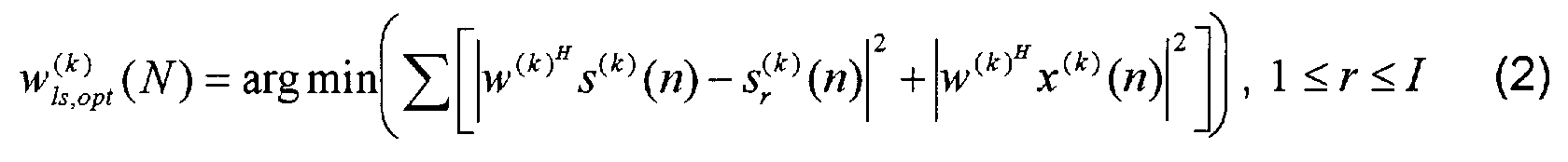


- In the following the Calibrated Weighted Recursive Least Squares (CW-RLS) algorithm is derived. It is a characteristic feature of the CW-RLS algorithm that it introduces a weighting factor on the observed signal correlation matrix estimates, and also uses pre-calculated source correlation estimates in equation (4). The algorithm also achieves this update recursively.
- An exponential weighting factor λ, 0 < λ < 1, which may also be referred to as a "forgetting factor", is introduced in the second part of equation (2) according to


- First, the total correlation matrix is introduced:


- The effect of this updating is that the total correlation matrix is weighted, and that both the rank one "correction term" x (k) (n)x


- One way to circumvent the matrix inversion and thus substantially reduce the complexity of the calculations is to update the total correlation matrix by adding scaled eigenvectors of the estimated source correlation matrix, which will result in several, and simpler, rank one updates as


- One simple way to further reduce the complexity is sequentially adding one scaled eigenvector at each sample instance. This is easily achieved by replacing the index ρ in equation (10) by the single index ρ = (n mod I) + 1. When the statistical properties of the environmental noise change abruptly, eg when a new source of disturbance suddenly appears, a smoothing of the weights may be appropriate. A first order auto regressive (AR) model is preferred for the smoothing, and the weight update then becomes

- The method of beam forming according to the invention has two main phases. In the first phase, information on the desired signal source alone is gathered. The first phase will be referred to as the calibration phase. The second phase is referred to as the operation phase.
- In the calibration phase, in principle, the desired signal source such as a speaking person is active alone. With the arrangement in figure 1 sound signals from a speaking person are captured by the array of microphones. Output signals from the first plurality l microphones are filtered in the filter banks, whereby for each microphone a second plurality K of band pass filtered signals covering distinct frequency bands are derived from the microphone signals. For each of the distinct frequency sub-bands the estimated source correlation matrix R̂


- The calibration may be performed in an initial phase and in quiet environments, but the system will preferably perform the calibration also during the operation phase at times where there are reasons to believe that undesired sounds such as background noise are of minor importance and have a negligible influence on the estimation of the source correlation matrix. Thereby the estimated source correlation matrix R̂

- The calibration is performed as follows. With the desired signal source, eg a speaking person, as the only or at least the dominating sound source, the microphone signal vector


- The correlation matrices are stored in diagonalized form:

- The eigenvectors are denoted


- For each frequency sub-band k, the eigenvectors q


- In the operation phase it is thus assumed that, for each of the K distinct frequency sub-bands, the estimated source correlation matrix R̂


- In each of the K frequency sub-bands, the following variables are used:
- beam former weighting vectors:

- the inverse of the total correlation matrix variable at time instant n, for frequency sub-band number k: P


- the forgetting factor λ for the WRLS algorithm and a weight smoothing factor α for the weighting factor update, which are preferably both chosen as constants for all frequency sub-bands:

- The algorithm is as follows. When any two or more of the sound sources (speech and noise) are active simultaneously, the following quantities are computed for each sample n and for each frequency sub-band k:


- For each frequency sub-band k the output from the corresponding beam former then is:

- The algorithm is then repeated for the next sample n+1, etc.
- In the operation phase the microphone output signals are continuously decomposed into discrete frequency sub-bands. The sub-band weighting factors w (k) are updated by making use of both the stored correlation estimates and of the actual microphone observations. The totality of beam former output signals, which each is a beam formed frequency sub-band time-domain signal, are input to a reconstruction filter bank. The output of the reconstruction filter bank is taken as the estimate of the sound signal from the desired sound source. Once the correlation estimates are stored in the memory, the algorithm is continuously adapting.
- The algorithm contains a step in which a rank one update of the correlation matrix is performed using scaled eigenvectors, one eigenvector for each new input data vector. This step adds correlation estimates from the source signal, whereby information gathered in the acquisition or calibration phase will remain a constant part of the correlation matrix, while the contributions form the undesired environmental noise will be subject to the forgetting factor λ in the estimates.
- Good performance of the algorithm of the invention requires that the number K of frequency sub-bands is large enough for the frequency-domain representation to be accurate. In other words, the number of frequency sub-bands is proportional to the length of the equivalent time-domain filters (filter length = the number of parameters used in a digital filter), and the number of degrees of freedom in the beam formers increases with the number of frequency sub-bands. Also, the delay caused by the frequency transformations is related to the number of frequency sub-bands.
- Time-domain and frequency-domain representations are closely related, and the algorithm of the invention can easily be extended to a combination of time-domain and frequency-domain representations. Each frequency sub-band signal can also be regarded as a time-domain signal samples at a reduced sampling rate, ie proportional to the frequency sub-band bandwidth, and having substantially only the frequencies in the sub-band. By applying the time-domain algorithm in each frequency sub-band, the degrees of freedom for the band-pass filters are increased, while the number of sub-bands may be kept constant. The lengths of the sub-band filters may differ between sub-bands, and the consequence is that a multi-resolution sub-band identification is obtained.
- The extension of the algorithm is achieved simply by using more lags from the observed microphone signals x


- The definitions of the correlation matrix, the eigenvalue and eigenvector matrices follow directly, and the size of the matrices will be increased by the factor L (k) · L (k) for frequency sub-band number k. The amount of memory needed to store the eigenvectors and the eigenvalues increases with increasing number of sub-band used.
- The band-pass filtering or decomposition of the broadband microphone signals into frequency sub-bands is preferably done using a uniform Discrete Fourier Transform (DFT), eg as described in [6], to decompose the full-rate sampled signals x i (n) into K sub-band signals. The sub-bands are preferably created in such a way that a prototype filter with a low-pass characteristic is used to ensure that the response from the k-th sub-band is the same as that of the prototype filter, although centred at a normalized frequency 2πk/K, whereby the set of K sub-bands will cover the whole frequency range. In a modulated filter bank the prototype filter equals one of the filters in the bank (usually the first filter), and the other filters are modulated versions of the prototype filter. Thus only the prototype filter needs to be created. Each sub-band signal is thereby represented in the base band. The filter bank should cover the entire frequency range, and a redundant, ie over-complete, frequency sub-band decomposition and reconstruction should be used. The invention is not limited to using uniformly distributed frequency sub-bands or a modulated filter bank.
- In order to reduce aliasing between sub-bands, the sub-band decomposition is made over-sampled.
- In the reconstruction filter bank a time domain signal is reconstructed or synthesized from the beam formed frequency sub-band signals from the beam formers. The beam formed frequency sub-band signals are up-converted from the base band to the actual frequency band, and summed in the reconstruction filter.
- In practical use, eg for hands-free operation of a mobile telephone in a car, the microphone array can eg have six microphones in a linear configuration with a spacing of 50 mm between microphones, and the microphone array can be placed at a nominal distance of eg 350 mm from the speaker's mouth. The number K of band pass filters in each filter bank can be in the range from 32 or less to 256 or more, typically 64.
-
K = total number of frequency sub-bands
k = index number of frequency sub-band, 0 ≤ k ≤ K-1
I = number of microphone channels, ie number of microphones in the array
i = microphone index in the array, 1 ≤ i ≤ /
N = number of samples
n = time signal sample number, sample instant
x(
y = output signal from beam formers
z e j2πf
R̂
r̂
R̂
R̂
w
λ = forgetting factor, 0 < λ< 1, typical value: λ= 0.99
α = weight smoothing factor, typical value: α = 0.01
q
γ
-
- [1] J. E. Hudson, "Adaptive Array Principles", Peter Peregrinus Ltd., 1991, ISBN 0-86341-247-5.
- [2] S. Haykin, "Adaptive Filter Theory", Prentice Hall International, Inc., 1996, ISBN 0-13-397985-7.
- [3] M. M. Goulding, J. S. Bird, "Speech Enhancement for Mobile Telephony", IEEE Transactions on Vehicular Technology, vol. 39, no. 4, pp. 316-326, November 1990.
- [4] S. Nordholm, V. Rehbock, K. L. Toe, S. Nordebo, "Chebyshev Optimization for the Design of Broadband Beam formers in the Nearfield", IEEE Transactions on Circuits and Systems II: Analog and Digital Signal Processing, vol. 45, pp. 141-143, 1998.
- [5] S. Nordholm, Y. H. Leung, "Performance Limits of the Generalized Sidelobe Cancelling Structure in an Isotropic Noise Field", Journal of the Acoustical Society of America, vol. 107, no. 2, pp. 1057-1060, February 2000.
- [6] Mitra, Sanjit Kumar, "Digital Signal Processing", McGraw-Hill Companies Inc., 1998, ISBN 0-07-042953-7.
Claims (6)
- A method of enhancing received desired sound signals from a desired sound source and of suppressing received undesired sound signals from one or more undesired sound sources, the method comprising- receiving, at different distinct locations, a first plurality (I) of sound signals and converting each of the received sound signals into a corresponding electrical signal representing an individual one of the received sound signals,- deriving, from each of the electrical signals representing individual ones of the received sound signals, a second plurality (K) of signals representing band pass filtered signals each covering a distinct frequency band- for each of the distinct frequency bands, beam forming the second plurality (K) of band pass filtered signals covering the corresponding distinct frequency band to have a maximum sensitivity at a region including the desired sound source while attenuating the undesired signals, and- combining the beam formed band pass filtered signals to an output signal.
- A method according to claim 1, wherein the beam forming is based on temporal and/or spatial information on the desired sound source.
- A method according to claim 1, wherein the beam forming is based on temporal and/or spatial information on the undesired sound source or sources.
- A method according to claim 2, wherein, for each of the second plurality (K) of distinct frequency bands, an estimated source correlation matrix


where
x
x


- A method according to any one of claims 3-4, wherein, for each of the second plurality (K) of distinct frequency bands, an estimated interference correlation matrix

- A method according to any one of claims 1-5, wherein beam former matrix weighting factors are updated exponentially in time.
Priority Applications (1)
| Application Number | Priority Date | Filing Date | Title |
|---|---|---|---|
| EP02388021A EP1343351A1 (en) | 2002-03-08 | 2002-03-08 | A method and an apparatus for enhancing received desired sound signals from a desired sound source and of suppressing undesired sound signals from undesired sound sources |
Applications Claiming Priority (1)
| Application Number | Priority Date | Filing Date | Title |
|---|---|---|---|
| EP02388021A EP1343351A1 (en) | 2002-03-08 | 2002-03-08 | A method and an apparatus for enhancing received desired sound signals from a desired sound source and of suppressing undesired sound signals from undesired sound sources |
Publications (1)
| Publication Number | Publication Date |
|---|---|
| EP1343351A1 true EP1343351A1 (en) | 2003-09-10 |
Family
ID=27741261
Family Applications (1)
| Application Number | Title | Priority Date | Filing Date |
|---|---|---|---|
| EP02388021A Withdrawn EP1343351A1 (en) | 2002-03-08 | 2002-03-08 | A method and an apparatus for enhancing received desired sound signals from a desired sound source and of suppressing undesired sound signals from undesired sound sources |
Country Status (1)
| Country | Link |
|---|---|
| EP (1) | EP1343351A1 (en) |
Cited By (9)
| Publication number | Priority date | Publication date | Assignee | Title |
|---|---|---|---|---|
| EP1475997A2 (en) * | 2003-05-09 | 2004-11-10 | Harman/Becker Automotive Systems GmbH | Method and system for communication enhancement in a noisy environment |
| US7643641B2 (en) | 2003-05-09 | 2010-01-05 | Nuance Communications, Inc. | System for communication enhancement in a noisy environment |
| US8260442B2 (en) * | 2008-04-25 | 2012-09-04 | Tannoy Limited | Control system for a transducer array |
| US8724822B2 (en) | 2003-05-09 | 2014-05-13 | Nuance Communications, Inc. | Noisy environment communication enhancement system |
| US9502050B2 (en) | 2012-06-10 | 2016-11-22 | Nuance Communications, Inc. | Noise dependent signal processing for in-car communication systems with multiple acoustic zones |
| CN106303838A (en) * | 2015-06-25 | 2017-01-04 | 宏达国际电子股份有限公司 | Sound processing apparatus and method |
| US9613633B2 (en) | 2012-10-30 | 2017-04-04 | Nuance Communications, Inc. | Speech enhancement |
| US9805738B2 (en) | 2012-09-04 | 2017-10-31 | Nuance Communications, Inc. | Formant dependent speech signal enhancement |
| US10623854B2 (en) | 2015-03-25 | 2020-04-14 | Dolby Laboratories Licensing Corporation | Sub-band mixing of multiple microphones |
Citations (1)
| Publication number | Priority date | Publication date | Assignee | Title |
|---|---|---|---|---|
| JP2002062348A (en) * | 2000-08-24 | 2002-02-28 | Sony Corp | Apparatus and method for processing signal |
-
2002
- 2002-03-08 EP EP02388021A patent/EP1343351A1/en not_active Withdrawn
Patent Citations (2)
| Publication number | Priority date | Publication date | Assignee | Title |
|---|---|---|---|---|
| JP2002062348A (en) * | 2000-08-24 | 2002-02-28 | Sony Corp | Apparatus and method for processing signal |
| US20020048376A1 (en) * | 2000-08-24 | 2002-04-25 | Masakazu Ukita | Signal processing apparatus and signal processing method |
Non-Patent Citations (4)
| Title |
|---|
| DAHL M ET AL: "ACOUSTIC NOISE AND ECHO CANCELING WITH MICROPHONE ARRAY", IEEE TRANSACTIONS ON VEHICULAR TECHNOLOGY, IEEE INC. NEW YORK, US, vol. 48, no. 5, September 1999 (1999-09-01), pages 1518 - 1526, XP000912523, ISSN: 0018-9545 * |
| LLEIDA E ET AL: "Robust continuous speech recognition system based on a microphone array", ACOUSTICS, SPEECH AND SIGNAL PROCESSING, 1998. PROCEEDINGS OF THE 1998 IEEE INTERNATIONAL CONFERENCE ON SEATTLE, WA, USA 12-15 MAY 1998, NEW YORK, NY, USA,IEEE, US, 12 May 1998 (1998-05-12), pages 241 - 244, XP010279154, ISBN: 0-7803-4428-6 * |
| PATENT ABSTRACTS OF JAPAN vol. 2002, no. 06 4 June 2002 (2002-06-04) * |
| SYDOW C: "BROADBAND BEAMFORMING FOR A MICROPHONE ARRAY", JOURNAL OF THE ACOUSTICAL SOCIETY OF AMERICA, AMERICAN INSTITUTE OF PHYSICS. NEW YORK, US, vol. 96, no. 2, PART 1, 1 August 1994 (1994-08-01), pages 845 - 849, XP000466113, ISSN: 0001-4966 * |
Cited By (14)
| Publication number | Priority date | Publication date | Assignee | Title |
|---|---|---|---|---|
| US8724822B2 (en) | 2003-05-09 | 2014-05-13 | Nuance Communications, Inc. | Noisy environment communication enhancement system |
| EP1475997A2 (en) * | 2003-05-09 | 2004-11-10 | Harman/Becker Automotive Systems GmbH | Method and system for communication enhancement in a noisy environment |
| EP1475997A3 (en) * | 2003-05-09 | 2004-12-22 | Harman/Becker Automotive Systems GmbH | Method and system for communication enhancement in a noisy environment |
| WO2004100602A3 (en) * | 2003-05-09 | 2005-01-06 | Harman Becker Automotive Sys | Method and system for communication enhancement ina noisy environment |
| US7643641B2 (en) | 2003-05-09 | 2010-01-05 | Nuance Communications, Inc. | System for communication enhancement in a noisy environment |
| US9002028B2 (en) | 2003-05-09 | 2015-04-07 | Nuance Communications, Inc. | Noisy environment communication enhancement system |
| WO2004100602A2 (en) * | 2003-05-09 | 2004-11-18 | Harman Becker Automotive Systems Gmbh | Method and system for communication enhancement ina noisy environment |
| US8260442B2 (en) * | 2008-04-25 | 2012-09-04 | Tannoy Limited | Control system for a transducer array |
| US9502050B2 (en) | 2012-06-10 | 2016-11-22 | Nuance Communications, Inc. | Noise dependent signal processing for in-car communication systems with multiple acoustic zones |
| US9805738B2 (en) | 2012-09-04 | 2017-10-31 | Nuance Communications, Inc. | Formant dependent speech signal enhancement |
| US9613633B2 (en) | 2012-10-30 | 2017-04-04 | Nuance Communications, Inc. | Speech enhancement |
| US10623854B2 (en) | 2015-03-25 | 2020-04-14 | Dolby Laboratories Licensing Corporation | Sub-band mixing of multiple microphones |
| CN106303838A (en) * | 2015-06-25 | 2017-01-04 | 宏达国际电子股份有限公司 | Sound processing apparatus and method |
| CN106303838B (en) * | 2015-06-25 | 2019-08-02 | 宏达国际电子股份有限公司 | Sound processing apparatus and method |
Similar Documents
| Publication | Publication Date | Title |
|---|---|---|
| US10446171B2 (en) | Online dereverberation algorithm based on weighted prediction error for noisy time-varying environments | |
| Simmer et al. | Post-filtering techniques | |
| US7206418B2 (en) | Noise suppression for a wireless communication device | |
| JP4989967B2 (en) | Method and apparatus for noise reduction | |
| CN106710601B (en) | Noise-reduction and pickup processing method and device for voice signals and refrigerator | |
| US8374358B2 (en) | Method for determining a noise reference signal for noise compensation and/or noise reduction | |
| US7366662B2 (en) | Separation of target acoustic signals in a multi-transducer arrangement | |
| EP2936830B1 (en) | Filter and method for informed spatial filtering using multiple instantaneous direction-of-arrivial estimates | |
| JP3373306B2 (en) | Mobile radio device having speech processing device | |
| US9224393B2 (en) | Noise estimation for use with noise reduction and echo cancellation in personal communication | |
| US8565446B1 (en) | Estimating direction of arrival from plural microphones | |
| US20160066087A1 (en) | Joint noise suppression and acoustic echo cancellation | |
| KR100878992B1 (en) | Geometric source separation signal processing technique | |
| KR100316116B1 (en) | Noise reduction systems and devices, mobile radio stations | |
| JP5762956B2 (en) | System and method for providing noise suppression utilizing nulling denoising | |
| US9818424B2 (en) | Method and apparatus for suppression of unwanted audio signals | |
| EP1592282B1 (en) | Teleconferencing method and system | |
| EP2234105B1 (en) | Background noise estimation | |
| WO2007123047A1 (en) | Adaptive array control device, method, and program, and its applied adaptive array processing device, method, and program | |
| CN111213359A (en) | Echo canceller and method for echo canceller | |
| EP1343351A1 (en) | A method and an apparatus for enhancing received desired sound signals from a desired sound source and of suppressing undesired sound signals from undesired sound sources | |
| Nordholm et al. | Optimal and adaptive microphone arrays for speech input in automobiles | |
| US20050008143A1 (en) | Echo canceller having spectral echo tail estimator | |
| Nordholm et al. | Performance limits in subband beamforming | |
| US7010556B1 (en) | Antenna treatment method and system |
Legal Events
| Date | Code | Title | Description |
|---|---|---|---|
| PUAI | Public reference made under article 153(3) epc to a published international application that has entered the european phase |
Free format text: ORIGINAL CODE: 0009012 |
|
| AK | Designated contracting states |
Kind code of ref document: A1 Designated state(s): AT BE CH CY DE DK ES FI FR GB GR IE IT LI LU MC NL PT SE TR |
|
| AX | Request for extension of the european patent |
Extension state: AL LT LV MK RO SI |
|
| RAP1 | Party data changed (applicant data changed or rights of an application transferred) |
Owner name: TELEFONAKTIEBOLAGET LM ERICSSON (PUBL) |
|
| AKX | Designation fees paid | ||
| REG | Reference to a national code |
Ref country code: DE Ref legal event code: 8566 |
|
| STAA | Information on the status of an ep patent application or granted ep patent |
Free format text: STATUS: THE APPLICATION IS DEEMED TO BE WITHDRAWN |
|
| 18D | Application deemed to be withdrawn |
Effective date: 20040311 |