EP1343278A1 - Facilitating IP-Based multicasting control connections over ATM - Google Patents
Facilitating IP-Based multicasting control connections over ATM Download PDFInfo
- Publication number
- EP1343278A1 EP1343278A1 EP03001816A EP03001816A EP1343278A1 EP 1343278 A1 EP1343278 A1 EP 1343278A1 EP 03001816 A EP03001816 A EP 03001816A EP 03001816 A EP03001816 A EP 03001816A EP 1343278 A1 EP1343278 A1 EP 1343278A1
- Authority
- EP
- European Patent Office
- Prior art keywords
- module
- dslam
- network
- gateway
- network node
- Prior art date
- Legal status (The legal status is an assumption and is not a legal conclusion. Google has not performed a legal analysis and makes no representation as to the accuracy of the status listed.)
- Withdrawn
Links
- 238000012546 transfer Methods 0.000 claims abstract description 7
- 238000004891 communication Methods 0.000 claims description 54
- 238000000034 method Methods 0.000 claims description 10
- 230000008878 coupling Effects 0.000 claims 2
- 238000010168 coupling process Methods 0.000 claims 2
- 238000005859 coupling reaction Methods 0.000 claims 2
- 238000010586 diagram Methods 0.000 description 9
- 238000013459 approach Methods 0.000 description 4
- 238000009420 retrofitting Methods 0.000 description 3
- 230000006870 function Effects 0.000 description 2
- 238000012986 modification Methods 0.000 description 1
- 230000004048 modification Effects 0.000 description 1
- 238000012545 processing Methods 0.000 description 1
Images




Classifications
-
- H—ELECTRICITY
- H04—ELECTRIC COMMUNICATION TECHNIQUE
- H04L—TRANSMISSION OF DIGITAL INFORMATION, e.g. TELEGRAPHIC COMMUNICATION
- H04L12/00—Data switching networks
- H04L12/54—Store-and-forward switching systems
- H04L12/56—Packet switching systems
- H04L12/5601—Transfer mode dependent, e.g. ATM
-
- H—ELECTRICITY
- H04—ELECTRIC COMMUNICATION TECHNIQUE
- H04L—TRANSMISSION OF DIGITAL INFORMATION, e.g. TELEGRAPHIC COMMUNICATION
- H04L12/00—Data switching networks
- H04L12/66—Arrangements for connecting between networks having differing types of switching systems, e.g. gateways
-
- H—ELECTRICITY
- H04—ELECTRIC COMMUNICATION TECHNIQUE
- H04L—TRANSMISSION OF DIGITAL INFORMATION, e.g. TELEGRAPHIC COMMUNICATION
- H04L47/00—Traffic control in data switching networks
- H04L47/10—Flow control; Congestion control
- H04L47/15—Flow control; Congestion control in relation to multipoint traffic
-
- H—ELECTRICITY
- H04—ELECTRIC COMMUNICATION TECHNIQUE
- H04Q—SELECTING
- H04Q11/00—Selecting arrangements for multiplex systems
- H04Q11/04—Selecting arrangements for multiplex systems for time-division multiplexing
- H04Q11/0428—Integrated services digital network, i.e. systems for transmission of different types of digitised signals, e.g. speech, data, telecentral, television signals
- H04Q11/0478—Provisions for broadband connections
-
- H—ELECTRICITY
- H04—ELECTRIC COMMUNICATION TECHNIQUE
- H04L—TRANSMISSION OF DIGITAL INFORMATION, e.g. TELEGRAPHIC COMMUNICATION
- H04L12/00—Data switching networks
- H04L12/54—Store-and-forward switching systems
- H04L12/56—Packet switching systems
- H04L12/5601—Transfer mode dependent, e.g. ATM
- H04L2012/5603—Access techniques
- H04L2012/5609—Topology
- H04L2012/561—Star, e.g. cross-connect, concentrator, subscriber group equipment, remote electronics
-
- H—ELECTRICITY
- H04—ELECTRIC COMMUNICATION TECHNIQUE
- H04L—TRANSMISSION OF DIGITAL INFORMATION, e.g. TELEGRAPHIC COMMUNICATION
- H04L12/00—Data switching networks
- H04L12/54—Store-and-forward switching systems
- H04L12/56—Packet switching systems
- H04L12/5601—Transfer mode dependent, e.g. ATM
- H04L2012/5638—Services, e.g. multimedia, GOS, QOS
- H04L2012/564—Connection-oriented
- H04L2012/5642—Multicast/broadcast/point-multipoint, e.g. VOD
-
- H—ELECTRICITY
- H04—ELECTRIC COMMUNICATION TECHNIQUE
- H04L—TRANSMISSION OF DIGITAL INFORMATION, e.g. TELEGRAPHIC COMMUNICATION
- H04L12/00—Data switching networks
- H04L12/54—Store-and-forward switching systems
- H04L12/56—Packet switching systems
- H04L12/5601—Transfer mode dependent, e.g. ATM
- H04L2012/5638—Services, e.g. multimedia, GOS, QOS
- H04L2012/5665—Interaction of ATM with other protocols
- H04L2012/5667—IP over ATM
Definitions
- IP Internet Protocol
- IP multicast control In conventional implementations of Internet Protocol (IP) multicast control, such control is often performed using a node-by-node, hop-by-hop approach. In this manner, each network node in a particular network of network nodes participates in the control of IP multicast connections. It is required that each network node has awareness at an IP control layer for enabling each network node to participate in the control of IP multicast connections.
- IP Internet Protocol
- ATM Asynchronous Transfer Mode
- deployed ATM network nodes i.e. deployed ATM network nodes.
- ATM Asynchronous Transfer Mode
- Insufficient memory in data processors of such deployed ATM network nodes is one reason why it would not be feasible or desirable to retrofit IP layer capabilities into deployed ATM network nodes of such networks. Such insufficient memory limits an ability to terminate an IP stack. Insufficient hardware resources for terminating additional IP connections and traffic is another reason why it is not feasible or desirable to retrofit IP layer capabilities into deployed ATM network nodes of such networks.
- IP-based hardware capable of supporting IP-based multicast services in deployed ATM network nodes is one reason why it is often not desirable (e.g. financially practical) to retrofit such IP-based hardware into deployed ATM network nodes.
- the significant cost associated with retrofitting such IP-based hardware into deployed ATM network nodes is another reason why it is often not desirable to retrofit deployed ATM network nodes with IP-based hardware.
- Still another reason is that a considerable duration of time and considerable coordination is required for retrofitting such IP-based hardware into a potentially large number of deployed ATM network nodes.
- IP multicast control functionality The term centralized as referred to herein means that such IP multicast control functionality is managed at a single one of a plurality of network nodes. This approach to managing control connections is in contrast to conventional multicast control approaches in which a plurality of network node participate in managing IP multicast control functionality in a node-by-node, hop-by-hop manner. It should be understood that the term centralized does not necessarily refer to a particular location of the network node or apparatus managing such IP multicast control functionality within a network. Accordingly, the network node or apparatus managing such IP multicast control functionality within a network may not be located at a central location within the network.
- Embodiments of the disclosures made herein provide a feasible and practical approach to retrofitting IP multicast control capabilities into deployed network nodes that are incapable of supporting IP layer capabilities or that have insufficient IP layer resources for supporting IP multicasting control capabilities.
- such embodiments of the disclosures made herein enable cost-effective deployment of IP multicasting capabilities in a subtending tree of network elements (e.g. Digital Subscriber Line Access Multiplexors - DSLAMS) that operate at an ATM layer.
- IP functionality is simulated at the ATM layer.
- the centralized IP multicast control functionality may be integrated into the root of a hierarchical tree of ATM capable network nodes (i.e. a DSLAM), at a network node external to the tree, or within tree.
- the communication apparatus 100 includes a hub Digital Subscriber Line Access Multiplexer (DSLAM) 102, a first subtended DSLAM 104, a second subtended DSLAM 106 and a plurality of DSL subscriber apparatuses 108. Although two subtended DSLAMs are shown, it is contemplated that the communication apparatus 100 and other apparatuses in accordance with embodiments of the disclosures made herein may include fewer or more than two subtended DSLAMS.
- a computer system having a DSL modem connected thereto is an example of a DSL subscriber apparatus.
- the communication apparatus 100 depicts an example of a tree of DSLAMs being controlled by the IP gateway module 116, wherein the IP gateway module 116 is internal to the tree.
- the first and the second subtended DSLAMS (104, 106) define a branch of subtended DSLAMs. It is contemplated herein that one or more other branches of subtended DSLAMs (not shown) may be connected to the hub DSLAM 102.
- a DSLAM is one example of a network element of a network node.
- the hub DSLAM 102, the first DSLAM 104 and the second DSLAM 106 are examples of network elements of respective network nodes.
- Such respective network nodes may comprise one or more DSLAMs as well as other types of network elements.
- the hub DSLAM 102 includes a network element control module 110, a DSL interface module 112, a subtending interface module 114 and an IP gateway module 116.
- the network element control module 110, the DSL interface module 112, the subtending interface module 114 and the IP gateway module 116 are interconnected for enabling communication therebetween.
- the network element control module 110 at least partially controls operation of various network elements (e.g. the DSL interface module 112, the subtending interface module 114 and the IP gateway module 116, etc) of the hub DSLAM 102.
- the DSL Interface module 112 enables communication between the hub DSLAM 102 and the plurality of DSL subscriber apparatus 108 connected to the hub DSLAM 102.
- the subtending interface module 114 supports communication between the hub DSLAM 102 and the first subtended DSLAM 104.
- the IP gateway module 116 manages IP multicast control functionality between the hub DSLAM 102 and at least a portion of the DSLAMs that subtend from the hub DSLAM 102 (e.g. the first subtending DSLAM 104 and the second subtending DSLAM 106). Managing multicast control connections is an example of managing multicast control functionality. Furthermore, the IP gateway module 116 manages IP multicast control functionality between the hub DSLAM 102 and DSL subscriber apparatuses 108 connected to the Hub DSLAM 102 and to any subtending DSLAMs under its management. Additional details regarding the operation, implementation and advantages of an IP gateway module in accordance with embodiments of the disclosures made herein are discussed below.
- the first subtending DSLAM 104 includes a network element control module 118, a DSL interface module 120 and a subtending interface module 122.
- the network element control module 118, the DSL interface module 120 and the subtending interface module 122 are interconnected for enabling communication therebetween.
- the network element control module 118 at least partially controls operation of various network elements (e.g. the DSL interface module 120 and the subtending interface module 122) of the first subtending DSLAM 104.
- the network element control module 118 of the first subtended DSLAM 104 is connected to the subtending interface module 114 of the hub DSLAM 102, thus enabling communication between the hub DSLAM 102 and the first subtended DSLAM 104.
- the DSL Interface module 120 enables communication between the first subtended DSLAM 104 and the plurality of DSL subscriber apparatuses 108 connected to the first subtended DSLAM 104.
- the subtending interface module 122 supports communication between the first subtending DSLAM 104 and the second subtended DSLAM 106.
- the second subtending DSLAM 106 includes a network element control module 124, a DSL interface module 126 and a subtending interface module 128.
- the network element control module 124, the DSL interface module 126 and the subtending interface module 128 are interconnected for enabling communication therebetween.
- the network element control module 124 of the second subtended DSLAM 106 is connected to the subtending interface module 122 of the first subtended DSLAM 104, thus enabling communication between the first subtended DSLAM 104 and the second subtended DSLAM 106.
- the second subtended DSLAM 106 is capable of providing multicast control functionality that is essentially identical to that of the first subtending DSLAM 104.
- the architecture of the second subtending DSLAM 106 is essentially identical to that of the first subtending DSLAM 104.
- the architecture of the second subtending DSLAM 106 is different than that of the first subtending DSLAM 104, although the second subtending DSLAM 106 is capable of providing multicast control functionality that is essentially identical to that of the first subtending DSLAM 104.
- the network element control modules (118, 124) of the first and the second subtended DSLAMs (104, 106) each include a respective control protocol terminating module (119, 125).
- the IP gateway module 116 is implemented at an IP layer of the hub DSLAM 102 and the control protocol terminating modules (119, 125) are each implemented at an Asynchronous Transfer Mode (ATM) layer of the first and the second subtended DSLAMs (104, 106).
- the control protocol terminating modules (119, 125) are capable of terminating a control protocol of the IP gateway module 116.
- the IP gateway module 116 is capable managing multicast control functionality of the first and the second subtended DSLAMs (104, 106) and any other suitable configured subtended DSLAMs associated therewith.
- control protocol terminating module may be a separate module (e.g. a separate network element of a network node) rather than a module integrated within a network control module as depicted herein. It is further contemplated herein that functionality of a protocol terminating module in accordance with the disclosures made herein may be integrated with another module (e.g. the network element module, Subtending interface module, etc). In this manner, control protocol terminating functionality is provided without the need for a discrete or integrated control protocol termination module.
- centralized multicast control functionality in accordance with the disclosures made herein enable a control connection 130 to be established between the hub DSLAM 102 and each DSLAM subtended with respect to the hub DSLAM 102 (e.g. the first and the second subtended DSLAMs 104, 106).
- the IP gateway module 116 is able to instruct the network element control modules (118, 124) of the first and the second subtended DSLAMs (104, 106) to perform functions such as establishing and clearing multicast control connections.
- One or more network elements of each DSLAM e.g. network element control modules and/or subtending interface modules participate in enabling each control connection 130 being established.
- centralized multicast control functionality in accordance with the disclosures made herein enable control connections 132 to be established between the hub DSLAM 102 and each DSL subscriber apparatuses 108 of the communication apparatus 100 such that the DSL subscriber apparatuses 108 are able to communicate with the IP gateway module 116.
- One or more network elements of each DSLAM e.g. DSL interface modules, network element control modules and/or subtending interface modules participate in enabling each control connection 132 being established.
- FIGS. 5-8 depict a communication apparatus 200 in accordance with a second embodiment of the disclosures made herein.
- the communication apparatus 200 includes an IP gateway apparatus 201, a hub DSLAM 202, a first subtended DSLAM 204, a second subtended DSLAM 206 and a plurality of DSL subscriber apparatuses 208. Although two subtended DSLAMs are shown, it is contemplated that the communication apparatus 200 and other apparatuses in accordance with embodiments of the disclosures made herein may include fewer or more than two subtended DSLAMS.
- the communication apparatus 200 depicts an example of a tree of DSLAMs being controlled by the IP gateway 201, wherein the IP gateway apparatus 201 is external to the tree.
- the first and the second subtended DSLAMS (204, 206) define a branch of subtended DSLAMs. It is contemplated herein that one or more other branches of subtended DSLAMs (not shown) may be connected to the hub DSLAM 202.
- a DSLAM is one example of a network element of a network node.
- the hub DSLAM 202, the first DSLAM 204 and the second DSLAM 206 are examples of network elements of respective network nodes.
- Such respective network nodes may comprise one or more DSLAMs as well as other types of network elements.
- the hub DSLAM 202 includes a network element control module 210, a DSL interface module 212 and a subtending interface module 214.
- the network element control module 210, the DSL interface module 212 and the subtending interface module 214 are interconnected for enabling communication therebetween.
- the network element control module 210 at least partially controls operation of various network elements (e.g. the DSL interface module 212 and the subtending interface module 214, etc) of the hub DSLAM 202.
- the DSL Interface module 212 enables communication between the hub DSLAM 202 and the plurality of DSL subscriber apparatuses 208 connected to the hub DSLAM 202.
- the subtending interface module 214 supports communication between the hub DSLAM 202 and the first subtended DSLAM 204.
- the IP gateway apparatus 201 includes an IP gateway module 216 capable of managing IP multicast control functionality between the hub DSLAM 202 and at least a portion of the DSLAMs that subtend from the hub DSLAM 202 (e.g. the first subtending DSLAM 204 and the second subtending DSLAM 206). Furthermore, the IP gateway module 216 manages IP multicast control functionality between the hub DSLAM 202 and DSL subscriber apparatuses 208 connected to the Hub DSLAM 202 and to any subtending DSLAMs under its management. The IP gateway apparatus 201 is not implemented within the tree of DSLAMs.
- the IP gateway apparatus 201 is a device that is capable of being a network element within or adjacent to an ATM network that is serving the subtended tree of DSLAMs. Additional details regarding the operation, implementation and advantages of an IP gateway module in accordance with embodiments of the disclosures made herein are discussed below.
- the first subtending DSLAM 204 includes a network element control module 218, a DSL interface module 220 and a subtending interface module 222.
- the network element control module 218, the DSL interface module 220 and the subtending interface module 122 are interconnected for enabling communication therebetween.
- the network element control module 218 at least partially controls operation of various network elements (e.g. the DSL interface module 220 and the subtending interface module 222) of the first subtending DSLAM 204.
- the network element control module 218 of the first subtended DSLAM 204 is connected to the subtending interface module 214 of the hub DSLAM 202, thus enabling communication between the hub DSLAM 202 and the first subtended DSLAM 204.
- the DSL Interface module 220 enables communication between the first subtended DSLAM 104 and the plurality of DSL subscriber apparatuses 208 connected to the first subtended DSLAM 204.
- the subtending interface module 222 supports communication between the first subtending DSLAM 104 and the second subtended DSLAM 106.
- the second subtending DSLAM 206 includes a network element control module 224, a DSL interface module 226 and a subtending interface module 228.
- the network element control module 224, the DSL interface module 226 and the subtending interface module 228 are interconnected for enabling communication therebetween.
- the network element control module 224 of the second subtended DSLAM 206 is connected to the subtending interface module 222 of the first subtended DSLAM 204, thus enabling communication between the first subtended DSLAM 204 and the second subtended DSLAM 206.
- the second subtended DSLAM 206 is capable of providing multicast control functionality that is essentially identical to that of the first subtending DSLAM 204.
- the architecture of the second subtending DSLAM 206 is essentially identical to that of the first subtending DSLAM 204.
- the architecture of the second subtending DSLAM 206 is different than that of the first subtending DSLAM 204, although the second subtending DSLAM 206 is capable of providing multicast control functionality that is essentially identical to that of the first subtending DSLAM 204.
- the network element control modules (210, 218, 224) of the hub DSLAM 202, first subtended DSLAM 204 and the second subtended DSLAM 206 each include a respective control protocol terminating module (211, 219, 225).
- the IP gateway module 216 is implemented at an IP layer of the hub DSLAM 202 and the control protocol terminating modules (211, 219, 225) are each implemented at an Asynchronous Transfer Mode (ATM) layer of the hub DSLAM 202, the first subtended DSLAM 204 and the second subtended DSLAM 206.
- the control protocol terminating modules (219, 225) are capable of terminating a control protocol of the IP gateway module 216.
- the IP gateway module 216 is capable managing multicast control functionality of the first and the second subtended DSLAMs (204, 206) and any other suitable configured subtended DSLAMs associated therewith.
- centralized multicast control functionality in accordance with the disclosures made herein enable a control connection 230 to be established between the IP gateway apparatus 201 and each one of the DSLAMS (i.e. the hub DSLAM 202, the first subtended DSLAM 204 and the second subtended DSLAM 206).
- the IP gateway module 216 is able to instruct the network element control modules (218, 224) of the hub DSLAM 202, the first subtended DSLAM 204 and the second subtended DSLAM 206 to perform functions such as establishing and clearing multicast control connections.
- One or more network elements of each DSLAM participate in enabling each control connection 230 being established.
- centralized multicast control functionality in accordance with the disclosures made herein enable control connections 232 to be established between the IP gateway apparatus 201 and each DSL subscriber apparatuses 208 of the tree of DSLAMs such that the DSL subscriber apparatuses 208 are able to communicate with the IP gateway apparatus module 216.
- One or more network elements of each DSLAM e.g. DSL interface modules, network element control modules and/or subtending interface modules participate in enabling each control connection 232 being established.
- an IP gateway module and associated control protocol terminating modules each comprise one or more data processor programs implemented on existing deployed network node hardware.
- an IP gateway module and associated control protocol terminating modules may each include respective hardware components in addition to one or more data processor programs.
- the term data processor program is defined herein to refer to computer software, data processor algorithms or any other type of instruction code capable of controlling operations associated with a data processor.
- a microprocessor, microcontroller, microcomputer, digital signal processor, state machine, logic circuitry, and/or any device that manipulates digital information based on operational instruction, or in a predefined manner are examples of a data processor.
- a network element e.g. an IP gateway module, a control protocol terminating module, a network element controller, etc.
- functionality associated with the various modules disclosed herein may be integrated in a one or more ancillary modules to a network element control module, a DSL interface module, a subtending interface module and an IP gateway module. Accordingly, multicast control functionality in accordance with the disclosures made herein is not limited to being provided by a single particular module.
- One advantage of software of the control protocol terminating module is that its complexity and size is capable of being significantly simpler and smaller than software that would be required to implement comparable multicast control functionality in a conventional distributed (i.e. a node-by-node) manner. Because the size of the software of the control protocol terminating module is capable of being smaller and simpler with an IP Gateway based implementation in accordance with the disclosures made herein, there is greater potential that sufficient memory and processing resources may be found in the existing deployed network nodes. Accordingly, the need to retrofit hardware of the existing deployed network nodes for an IP Gateway based implementation in accordance with the disclosures made herein may be limited, if not avoided.
- IP layer and the ATM layer are examples of a first communication protocol layer and a second communication protocol layer, respectively. It is contemplated herein that multicast control functionality in accordance with the disclosures made herein may be implemented with a combination of communication protocols different than IP and ATM communication protocols. Accordingly, the disclosures made herein are not limited to IP and ATM communication protocols.
- FIG. 9 depicts a method 300 for facilitating IP multicasting functionality in accordance with an embodiment of the disclosures made herein.
- the method 300 begins at an operation 302 for implementing centralized multicast control functionality.
- the operation 302 for implementing centralized multicast control functionality includes performing a step 304 for implementing an IP Gateway module at an IP layer of a first network node and performing a step 304 for implementing a control protocol terminating module at an ATM layer of one or more network nodes (i.e. a second, network node, a third network node, etc) that are in subtending relationship with respect to the first network node.
- the one or more network nodes are referred to herein as subtending network nodes.
- an operation 308 is performed for establishing control connections within the network.
- the operation 308 for establishing such control connections includes performing a step 310 for establishing a control connection between the first network node and each of the one or more subtending network nodes and performing an operation 312 for establishing a control connection between the first network node and one or more subscriber DSL apparatuses that are themselves subtending from a respective one of the subtending network nodes.
- an operation 314 is capable of being performed for facilitating multicast file download in accordance with known techniques.
Landscapes
- Engineering & Computer Science (AREA)
- Computer Networks & Wireless Communication (AREA)
- Signal Processing (AREA)
- Data Exchanges In Wide-Area Networks (AREA)
Abstract
Description
- The disclosures made herein relate generally to Internet Protocol (IP) multicast techniques and more particularly to facilitating IP-based multicasting via a hierarchical network comprising network nodes that are incapable of supporting IP layer capabilities.
- In conventional implementations of Internet Protocol (IP) multicast control, such control is often performed using a node-by-node, hop-by-hop approach. In this manner, each network node in a particular network of network nodes participates in the control of IP multicast connections. It is required that each network node has awareness at an IP control layer for enabling each network node to participate in the control of IP multicast connections.
- Many public and private communication networks include hierarchical networks of Asynchronous Transfer Mode (ATM) layer equipment (i.e. deployed ATM network nodes). To provide new IP-based multicast services within such networks, it is necessary to enable IP multicasting capabilities within such networks. However, it is often not be feasible or desirable to retrofit IP layer capabilities or new hardware into deployed ATM network nodes of such networks.
- Insufficient memory in data processors of such deployed ATM network nodes is one reason why it would not be feasible or desirable to retrofit IP layer capabilities into deployed ATM network nodes of such networks. Such insufficient memory limits an ability to terminate an IP stack. Insufficient hardware resources for terminating additional IP connections and traffic is another reason why it is not feasible or desirable to retrofit IP layer capabilities into deployed ATM network nodes of such networks.
- The cost and time associated with designing IP-based hardware capable of supporting IP-based multicast services in deployed ATM network nodes is one reason why it is often not desirable (e.g. financially practical) to retrofit such IP-based hardware into deployed ATM network nodes. Similarly, the significant cost associated with retrofitting such IP-based hardware into deployed ATM network nodes is another reason why it is often not desirable to retrofit deployed ATM network nodes with IP-based hardware. Still another reason is that a considerable duration of time and considerable coordination is required for retrofitting such IP-based hardware into a potentially large number of deployed ATM network nodes.
- Therefore, facilitating centralized multicast control functionality in a hierarchical network of network elements in a manner that overcomes limitations associated with conventional implementations of IP multicasting capabilities is useful.
-
- FIG. 1 is a block diagram view depicting a hierarchical network of network nodes capable of facilitating multicast control functionality in accordance with a first embodiment of the disclosures made herein.
- FIG. 2 is a block diagram view depicting the relationship of network elements of the hierarchical network of network nodes depicted in FIG. 1 in relation to an IP layer and an ATM layer.
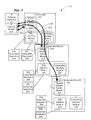
- FIG. 3 is a block diagram view depicting DSLAM control connections managed by an IP gateway module of the hierarchical network of network nodes depicted in FIG. 1.
- FIG. 4 is a block diagram view depicting DSL subscriber apparatus control connections managed by an IP gateway module of the hierarchical network of network nodes depicted in FIG. 1.
- FIG. 5 is a block diagram view depicting a hierarchical network of network nodes capable of facilitating multicast control functionality in accordance with a second embodiment of the disclosures made herein.
- FIG. 6 is a block diagram view depicting the relationship of network elements of the hierarchical network of network nodes depicted in FIG. 5 in relation to an IP layer and an ATM layer.
- FIG. 7 is a block diagram view depicting DSLAM control connections managed by an IP gateway module of the hierarchical network of network nodes depicted in FIG. 5.
- FIG. 8 is a block diagram view depicting DSL subscriber apparatus control connections managed by an IP gateway module of the hierarchical network of network nodes depicted in FIG. 5.
- FIG. 9 is a flow diagram view depicting a method for facilitating IP multicasting functionality in accordance with another embodiment of the disclosures made herein.
- The disclosures made herein relate to various aspects of centralizing Internet Protocol (IP) multicast control functionality. The term centralized as referred to herein means that such IP multicast control functionality is managed at a single one of a plurality of network nodes. This approach to managing control connections is in contrast to conventional multicast control approaches in which a plurality of network node participate in managing IP multicast control functionality in a node-by-node, hop-by-hop manner. It should be understood that the term centralized does not necessarily refer to a particular location of the network node or apparatus managing such IP multicast control functionality within a network. Accordingly, the network node or apparatus managing such IP multicast control functionality within a network may not be located at a central location within the network.
- Embodiments of the disclosures made herein provide a feasible and practical approach to retrofitting IP multicast control capabilities into deployed network nodes that are incapable of supporting IP layer capabilities or that have insufficient IP layer resources for supporting IP multicasting control capabilities. For example, such embodiments of the disclosures made herein enable cost-effective deployment of IP multicasting capabilities in a subtending tree of network elements (e.g. Digital Subscriber Line Access Multiplexors - DSLAMS) that operate at an ATM layer. Effectively, IP functionality is simulated at the ATM layer. It is contemplated herein that the centralized IP multicast control functionality may be integrated into the root of a hierarchical tree of ATM capable network nodes (i.e. a DSLAM), at a network node external to the tree, or within tree.
- Turning now to the drawing figures, a
communication apparatus 100 in accordance with a first embodiment of the disclosures made herein is disclosed in FIGS. 1-4. Thecommunication apparatus 100 includes a hub Digital Subscriber Line Access Multiplexer (DSLAM) 102, a first subtendedDSLAM 104, a second subtendedDSLAM 106 and a plurality ofDSL subscriber apparatuses 108. Although two subtended DSLAMs are shown, it is contemplated that thecommunication apparatus 100 and other apparatuses in accordance with embodiments of the disclosures made herein may include fewer or more than two subtended DSLAMS. A computer system having a DSL modem connected thereto is an example of a DSL subscriber apparatus. - The
communication apparatus 100 depicts an example of a tree of DSLAMs being controlled by theIP gateway module 116, wherein theIP gateway module 116 is internal to the tree. The first and the second subtended DSLAMS (104, 106) define a branch of subtended DSLAMs. It is contemplated herein that one or more other branches of subtended DSLAMs (not shown) may be connected to the hub DSLAM 102. - It should be understood that that a DSLAM is one example of a network element of a network node. Accordingly, the hub DSLAM 102, the first DSLAM 104 and the second DSLAM 106 are examples of network elements of respective network nodes. Such respective network nodes may comprise one or more DSLAMs as well as other types of network elements.
- The hub DSLAM 102 includes a network
element control module 110, aDSL interface module 112, asubtending interface module 114 and anIP gateway module 116. The networkelement control module 110, theDSL interface module 112, thesubtending interface module 114 and theIP gateway module 116 are interconnected for enabling communication therebetween. The networkelement control module 110 at least partially controls operation of various network elements (e.g. theDSL interface module 112, thesubtending interface module 114 and theIP gateway module 116, etc) of the hub DSLAM 102. TheDSL Interface module 112 enables communication between the hub DSLAM 102 and the plurality ofDSL subscriber apparatus 108 connected to the hub DSLAM 102. Thesubtending interface module 114 supports communication between the hub DSLAM 102 and the first subtendedDSLAM 104. - The
IP gateway module 116 manages IP multicast control functionality between the hub DSLAM 102 and at least a portion of the DSLAMs that subtend from the hub DSLAM 102 (e.g. the first subtendingDSLAM 104 and the second subtending DSLAM 106). Managing multicast control connections is an example of managing multicast control functionality. Furthermore, theIP gateway module 116 manages IP multicast control functionality between the hub DSLAM 102 andDSL subscriber apparatuses 108 connected to the Hub DSLAM 102 and to any subtending DSLAMs under its management. Additional details regarding the operation, implementation and advantages of an IP gateway module in accordance with embodiments of the disclosures made herein are discussed below. - The first subtending DSLAM 104 includes a network
element control module 118, aDSL interface module 120 and asubtending interface module 122. The networkelement control module 118, theDSL interface module 120 and thesubtending interface module 122 are interconnected for enabling communication therebetween. The networkelement control module 118 at least partially controls operation of various network elements (e.g. theDSL interface module 120 and the subtending interface module 122) of the first subtendingDSLAM 104. Furthermore, the networkelement control module 118 of the first subtendedDSLAM 104 is connected to thesubtending interface module 114 of the hub DSLAM 102, thus enabling communication between the hub DSLAM 102 and the first subtendedDSLAM 104. TheDSL Interface module 120 enables communication between the first subtendedDSLAM 104 and the plurality ofDSL subscriber apparatuses 108 connected to the first subtended DSLAM 104. Thesubtending interface module 122 supports communication between the first subtending DSLAM 104 and the second subtendedDSLAM 106. - The second subtending DSLAM 106 includes a network
element control module 124, aDSL interface module 126 and asubtending interface module 128. The networkelement control module 124, theDSL interface module 126 and thesubtending interface module 128 are interconnected for enabling communication therebetween. The networkelement control module 124 of the second subtendedDSLAM 106 is connected to thesubtending interface module 122 of the first subtendedDSLAM 104, thus enabling communication between the first subtendedDSLAM 104 and the second subtendedDSLAM 106. - The second subtended DSLAM 106 is capable of providing multicast control functionality that is essentially identical to that of the first subtending DSLAM 104. In a first embodiment of the second subtending DSLAM 106 (shown), the architecture of the
second subtending DSLAM 106 is essentially identical to that of thefirst subtending DSLAM 104. In a second embodiment of thesecond subtending DSLAM 106, the architecture of thesecond subtending DSLAM 106 is different than that of thefirst subtending DSLAM 104, although thesecond subtending DSLAM 106 is capable of providing multicast control functionality that is essentially identical to that of thefirst subtending DSLAM 104. - As depicted in FIG. 2, the network element control modules (118, 124) of the first and the second subtended DSLAMs (104, 106) each include a respective control protocol terminating module (119, 125). Furthermore, the
IP gateway module 116 is implemented at an IP layer of thehub DSLAM 102 and the control protocol terminating modules (119, 125) are each implemented at an Asynchronous Transfer Mode (ATM) layer of the first and the second subtended DSLAMs (104, 106). The control protocol terminating modules (119, 125) are capable of terminating a control protocol of theIP gateway module 116. In this manner, theIP gateway module 116 is capable managing multicast control functionality of the first and the second subtended DSLAMs (104, 106) and any other suitable configured subtended DSLAMs associated therewith. - It is contemplated herein that in other embodiments of a control protocol terminating module (not shown), the control protocol terminating module may be a separate module (e.g. a separate network element of a network node) rather than a module integrated within a network control module as depicted herein. It is further contemplated herein that functionality of a protocol terminating module in accordance with the disclosures made herein may be integrated with another module (e.g. the network element module, Subtending interface module, etc). In this manner, control protocol terminating functionality is provided without the need for a discrete or integrated control protocol termination module.
- As depicted in FIG. 3, centralized multicast control functionality in accordance with the disclosures made herein enable a
control connection 130 to be established between thehub DSLAM 102 and each DSLAM subtended with respect to the hub DSLAM 102 (e.g. the first and the second subtendedDSLAMs 104, 106). Accordingly, theIP gateway module 116 is able to instruct the network element control modules (118, 124) of the first and the second subtended DSLAMs (104, 106) to perform functions such as establishing and clearing multicast control connections. One or more network elements of each DSLAM (e.g. network element control modules and/or subtending interface modules) participate in enabling eachcontrol connection 130 being established. - As depicted in FIG. 4, centralized multicast control functionality in accordance with the disclosures made herein enable
control connections 132 to be established between thehub DSLAM 102 and eachDSL subscriber apparatuses 108 of thecommunication apparatus 100 such that theDSL subscriber apparatuses 108 are able to communicate with theIP gateway module 116. One or more network elements of each DSLAM (e.g. DSL interface modules, network element control modules and/or subtending interface modules) participate in enabling eachcontrol connection 132 being established. - FIGS. 5-8 depict a
communication apparatus 200 in accordance with a second embodiment of the disclosures made herein. Thecommunication apparatus 200 includes anIP gateway apparatus 201, ahub DSLAM 202, afirst subtended DSLAM 204, asecond subtended DSLAM 206 and a plurality ofDSL subscriber apparatuses 208. Although two subtended DSLAMs are shown, it is contemplated that thecommunication apparatus 200 and other apparatuses in accordance with embodiments of the disclosures made herein may include fewer or more than two subtended DSLAMS. - The
communication apparatus 200 depicts an example of a tree of DSLAMs being controlled by theIP gateway 201, wherein theIP gateway apparatus 201 is external to the tree. The first and the second subtended DSLAMS (204, 206) define a branch of subtended DSLAMs. It is contemplated herein that one or more other branches of subtended DSLAMs (not shown) may be connected to thehub DSLAM 202. - It should be understood that that a DSLAM is one example of a network element of a network node. Accordingly, the
hub DSLAM 202, thefirst DSLAM 204 and thesecond DSLAM 206 are examples of network elements of respective network nodes. Such respective network nodes may comprise one or more DSLAMs as well as other types of network elements. - The
hub DSLAM 202 includes a networkelement control module 210, aDSL interface module 212 and asubtending interface module 214. The networkelement control module 210, theDSL interface module 212 and thesubtending interface module 214 are interconnected for enabling communication therebetween. The networkelement control module 210 at least partially controls operation of various network elements (e.g. theDSL interface module 212 and thesubtending interface module 214, etc) of thehub DSLAM 202. TheDSL Interface module 212 enables communication between thehub DSLAM 202 and the plurality ofDSL subscriber apparatuses 208 connected to thehub DSLAM 202. The subtendinginterface module 214 supports communication between thehub DSLAM 202 and thefirst subtended DSLAM 204. - The
IP gateway apparatus 201 includes anIP gateway module 216 capable of managing IP multicast control functionality between thehub DSLAM 202 and at least a portion of the DSLAMs that subtend from the hub DSLAM 202 (e.g. thefirst subtending DSLAM 204 and the second subtending DSLAM 206). Furthermore, theIP gateway module 216 manages IP multicast control functionality between thehub DSLAM 202 andDSL subscriber apparatuses 208 connected to theHub DSLAM 202 and to any subtending DSLAMs under its management. TheIP gateway apparatus 201 is not implemented within the tree of DSLAMs. TheIP gateway apparatus 201 is a device that is capable of being a network element within or adjacent to an ATM network that is serving the subtended tree of DSLAMs. Additional details regarding the operation, implementation and advantages of an IP gateway module in accordance with embodiments of the disclosures made herein are discussed below. - The
first subtending DSLAM 204 includes a networkelement control module 218, aDSL interface module 220 and asubtending interface module 222. The networkelement control module 218, theDSL interface module 220 and thesubtending interface module 122 are interconnected for enabling communication therebetween. The networkelement control module 218 at least partially controls operation of various network elements (e.g. theDSL interface module 220 and the subtending interface module 222) of thefirst subtending DSLAM 204. Furthermore, the networkelement control module 218 of thefirst subtended DSLAM 204 is connected to thesubtending interface module 214 of thehub DSLAM 202, thus enabling communication between thehub DSLAM 202 and thefirst subtended DSLAM 204. TheDSL Interface module 220 enables communication between thefirst subtended DSLAM 104 and the plurality ofDSL subscriber apparatuses 208 connected to thefirst subtended DSLAM 204. The subtendinginterface module 222 supports communication between thefirst subtending DSLAM 104 and thesecond subtended DSLAM 106. - The
second subtending DSLAM 206 includes a networkelement control module 224, aDSL interface module 226 and asubtending interface module 228. The networkelement control module 224, theDSL interface module 226 and thesubtending interface module 228 are interconnected for enabling communication therebetween. The networkelement control module 224 of thesecond subtended DSLAM 206 is connected to thesubtending interface module 222 of thefirst subtended DSLAM 204, thus enabling communication between thefirst subtended DSLAM 204 and thesecond subtended DSLAM 206. - The
second subtended DSLAM 206 is capable of providing multicast control functionality that is essentially identical to that of thefirst subtending DSLAM 204. In a first embodiment of the second subtending DSLAM 206 (shown), the architecture of thesecond subtending DSLAM 206 is essentially identical to that of thefirst subtending DSLAM 204. In a second embodiment of thesecond subtending DSLAM 206, the architecture of thesecond subtending DSLAM 206 is different than that of thefirst subtending DSLAM 204, although thesecond subtending DSLAM 206 is capable of providing multicast control functionality that is essentially identical to that of thefirst subtending DSLAM 204. - As depicted in FIG. 6, the network element control modules (210, 218, 224) of the
hub DSLAM 202,first subtended DSLAM 204 and thesecond subtended DSLAM 206 each include a respective control protocol terminating module (211, 219, 225). Furthermore, theIP gateway module 216 is implemented at an IP layer of thehub DSLAM 202 and the control protocol terminating modules (211, 219, 225) are each implemented at an Asynchronous Transfer Mode (ATM) layer of thehub DSLAM 202, thefirst subtended DSLAM 204 and thesecond subtended DSLAM 206. The control protocol terminating modules (219, 225) are capable of terminating a control protocol of theIP gateway module 216. In this manner, theIP gateway module 216 is capable managing multicast control functionality of the first and the second subtended DSLAMs (204, 206) and any other suitable configured subtended DSLAMs associated therewith. - As depicted in FIG. 7, centralized multicast control functionality in accordance with the disclosures made herein enable a
control connection 230 to be established between theIP gateway apparatus 201 and each one of the DSLAMS (i.e. thehub DSLAM 202, thefirst subtended DSLAM 204 and the second subtended DSLAM 206). Accordingly, theIP gateway module 216 is able to instruct the network element control modules (218, 224) of thehub DSLAM 202, thefirst subtended DSLAM 204 and thesecond subtended DSLAM 206 to perform functions such as establishing and clearing multicast control connections. One or more network elements of each DSLAM (e.g. network element control modules and/or subtending interface modules) participate in enabling eachcontrol connection 230 being established. - Furthermore, as depicted in FIG. 8, centralized multicast control functionality in accordance with the disclosures made herein enable
control connections 232 to be established between theIP gateway apparatus 201 and eachDSL subscriber apparatuses 208 of the tree of DSLAMs such that theDSL subscriber apparatuses 208 are able to communicate with the IPgateway apparatus module 216. One or more network elements of each DSLAM (e.g. DSL interface modules, network element control modules and/or subtending interface modules) participate in enabling eachcontrol connection 232 being established. - In accordance with at least one embodiment of the disclosures made herein, an IP gateway module and associated control protocol terminating modules each comprise one or more data processor programs implemented on existing deployed network node hardware. In accordance with at least one other embodiment of the disclosures made herein, an IP gateway module and associated control protocol terminating modules may each include respective hardware components in addition to one or more data processor programs. The term data processor program is defined herein to refer to computer software, data processor algorithms or any other type of instruction code capable of controlling operations associated with a data processor. A microprocessor, microcontroller, microcomputer, digital signal processor, state machine, logic circuitry, and/or any device that manipulates digital information based on operational instruction, or in a predefined manner are examples of a data processor. A network element (e.g. an IP gateway module, a control protocol terminating module, a network element controller, etc.) may comprise such a data processor and a data processor program in accordance with embodiments of the disclosures made herein.
- It is contemplated herein that functionality associated with the various modules disclosed herein may be integrated in a one or more ancillary modules to a network element control module, a DSL interface module, a subtending interface module and an IP gateway module. Accordingly, multicast control functionality in accordance with the disclosures made herein is not limited to being provided by a single particular module.
- One advantage of software of the control protocol terminating module is that its complexity and size is capable of being significantly simpler and smaller than software that would be required to implement comparable multicast control functionality in a conventional distributed (i.e. a node-by-node) manner. Because the size of the software of the control protocol terminating module is capable of being smaller and simpler with an IP Gateway based implementation in accordance with the disclosures made herein, there is greater potential that sufficient memory and processing resources may be found in the existing deployed network nodes. Accordingly, the need to retrofit hardware of the existing deployed network nodes for an IP Gateway based implementation in accordance with the disclosures made herein may be limited, if not avoided.
- The IP layer and the ATM layer are examples of a first communication protocol layer and a second communication protocol layer, respectively. It is contemplated herein that multicast control functionality in accordance with the disclosures made herein may be implemented with a combination of communication protocols different than IP and ATM communication protocols. Accordingly, the disclosures made herein are not limited to IP and ATM communication protocols.
- FIG. 9 depicts a
method 300 for facilitating IP multicasting functionality in accordance with an embodiment of the disclosures made herein. Themethod 300 begins at anoperation 302 for implementing centralized multicast control functionality. Theoperation 302 for implementing centralized multicast control functionality includes performing astep 304 for implementing an IP Gateway module at an IP layer of a first network node and performing astep 304 for implementing a control protocol terminating module at an ATM layer of one or more network nodes (i.e. a second, network node, a third network node, etc) that are in subtending relationship with respect to the first network node. The one or more network nodes are referred to herein as subtending network nodes. - After performing the
operation 302 for implementing centralized multicast control functionality, anoperation 308 is performed for establishing control connections within the network. Accordingly, theoperation 308 for establishing such control connections includes performing astep 310 for establishing a control connection between the first network node and each of the one or more subtending network nodes and performing an operation 312 for establishing a control connection between the first network node and one or more subscriber DSL apparatuses that are themselves subtending from a respective one of the subtending network nodes. After the control connections are established with the one or more subtending network nodes and the one or more Subscriber DSL apparatuses, an operation 314 is capable of being performed for facilitating multicast file download in accordance with known techniques. - In the preceding detailed description, reference has been made to the accompanying drawings that form a part hereof, and in which are shown by way of illustration specific embodiments in which the invention may be practiced. These embodiments, and certain variants thereof, have been described in sufficient detail to enable those skilled in the art to practice the invention. It is to be understood that other suitable embodiments may be utilized and that logical, mechanical, chemical and electrical changes may be made without departing from the spirit or scope of the invention. For example, functional blocks shown in the figures could be further combined or divided in any manner without departing from the spirit or scope of the invention. To avoid unnecessary detail, the description omits certain information known to those skilled in the art. The preceding detailed description is, therefore, not intended to be limited to the specific forms set forth herein, but on the contrary, it is intended to cover such alternatives, modifications, and equivalents, as can be reasonably included within the spirit and scope of the appended claims.
Claims (37)
- An Internet Protocol (IP) multicast control system, comprising:a first module capable of facilitating IP multicast control connections between a first apparatus and a second apparatus; anda second module capable of enabling termination of a control protocol of the first module and capable of being supported at an Asynchronous Transfer Mode (ATM) layer of the second apparatus.
- The system of claim 1 wherein the first module is capable of being supported at the IP layer of the first apparatus.
- The system of claim 1 wherein the second apparatus is subtending with respect to the first apparatus.
- The system of claim 1 wherein:the first module is an IP Gateway Module; andthe second module is a control protocol terminating module.
- The system of claim 4 wherein:the first apparatus further includes:a Network Element Control Module;a Subtending Interface Module; anda Digital Subscriber Line (DSL) Interface Module; andthe IP Gateway Module, the Network Element Control Module, the Subtending Interface Module and the DSL Interface Module are each interconnected.
- The system of claim 1 wherein:the first apparatus further includes:a module capable of controlling a plurality of network elements of the first apparatus;a module capable of supporting communication with at least one subtending network node of the first apparatus; anda module capable of supporting communication with at least one Digital Subscriber Line (DSL) apparatus; and
each one of said modules is interconnected with each other one of said modules. - The system of claim 6 wherein:the first apparatus includes a first Digital Subscriber Line Multiplexor (DSLAM);the first DSLAM includes an IP layer;the IP Gateway Module is capable of being supported at the IP layer of the first apparatus; andthe IP Gateway Module is an network element of the first DSLAM.
- The system of claim 7 wherein the second apparatus is subtending with respect to the first DSLAM.
- The system of claim 8 wherein:the second apparatus includes a second DSLAM; andthe Gateway Control Protocol Terminating Module is a network element of the second DSLAM.
- The system of claim 1 wherein:the first apparatus includes an IP Gateway apparatus including an IP layer; andthe IP Gateway Module is a network element of the IP Gateway apparatus.
- The system of claim 10 wherein the IP Gateway Module is capable of being supported at the IP layer of the IP gateway apparatus.
- The system of claim 10 wherein the IP gateway apparatus and the second apparatus are network nodes of a common network of network nodes.
- The system of claim 12 wherein the common network operates in accordance with ATM.
- The system of claim 10 wherein:the second apparatus includes a DSLAM;the ATM layer is integral with the DSLAM; andthe Gateway Control Protocol Terminating Module is a network element of the DSLAM.
- The system of claim 10 wherein the IP gateway apparatus and the second apparatus are network nodes of a first network of network nodes and a second network of network nodes, respectively.
- The system of claim 15 wherein:the first network node operates in accordance with IP; andthe second network node operates in accordance with ATM.
- The system of claim 10 wherein:the second apparatus is a hub apparatus; anda third apparatus is a subtending apparatus with respect to the hub apparatus.
- A communication apparatus, comprising:a first network node including an Internet Protocol (IP) Gateway Module; anda second network node including a Gateway Control Protocol Terminating Module;wherein the IP Gateway Module is capable of facilitating IP multicast control connections between the first network node and the second network node and wherein the Gateway Control Protocol Terminating Module is capable of enabling termination of a control protocol of the IP Gateway Module and is capable of being supported at an Asynchronous Transfer Mode (ATM) layer of the second network node.
- The communication apparatus of claim 18 wherein the second network node is subtending with respect to the first network node.
- The communication apparatus of claim 18 wherein:the first network node includes a Digital Subscriber Line Multiplexor (DSLAM);the DSLAM includes an IP layer; andthe IP Gateway Module is an network element of the DSLAM.
- The communication apparatus of claim 20 wherein the IP Gateway Module is capable of being supported at the IP layer of the DSLAM.
- The communication apparatus of claim 20 wherein:the DSLAM further includes:a Network Element Control Module;a Subtending Interface Module; anda Digital Subscriber Line (DSL) Interface Module; andthe Network Element Control Module, the Subtending Interface Module and the DSL Interface Module are each interconnected.
- The communication apparatus of claim 20 wherein:the DSLAM further includes:a module capable of controlling a plurality of network elements of the DSLAM;a module capable of supporting communication with at least one subtending network node of the DSLAM; anda module capable of supporting communication with at least one Digital Subscriber Line (DSL) apparatus; and
each one of said modules is interconnected with each other one of said modules. - The communication apparatus of claim 20 wherein the second apparatus is subtending with respect to the first DSLAM.
- The communication apparatus of claim 24 wherein:the first network node includes a second DSLAM; andthe Gateway Control Protocol Terminating Module is a network element of the second DSLAM.
- The communication apparatus of claim 18 wherein:the first network node includes an IP Gateway apparatus including an IP layer; andthe IP Gateway Module is a network element of the IP Gateway apparatus.
- The communication apparatus of claim 26 wherein the IP Gateway Module is capable of being supported at the IP layer of the IP Gateway apparatus.
- The communication apparatus of claim 26 wherein the IP gateway apparatus and the second apparatus are network nodes of a common network of network nodes.
- The communication apparatus of claim 28 wherein the common network operates in accordance with ATM.
- The communication apparatus of claim 26 wherein the first network node and the second network node are network nodes of a first network of network nodes and a second network of network nodes, respectively.
- The communication apparatus of claim 30 wherein:the first network node operates in accordance with IP; andthe second network node operates in accordance with ATM.
- The communication apparatus of claim 26 wherein:the second network node is a hub network node; anda third network node is a subtending network node with respect to the hub network node.
- A method for facilitating Internet Protocol (IP) multicast services within a deployed network of network elements, comprising:implementing, at an IP layer of the first network node, functionality capable of controlling multicast connections between the first network node and a second network node an IP Gateway control protocol; andimplementing, at an Asynchronous Transfer Mode (ATM) layer of the second network node, functionality capable of terminating the IP Gateway control protocol.
- The method of claim 33 wherein:the first network node includes a Digital Subscriber Line Multiplexor (DSLAM);the IP layer is integral with the DSLAM; andimplementing said functionality capable of controlling multicast connections includes implementing said functionality at the IP layer of the DSLAM.
- The method of claim 33 wherein implementing said functionality capable of controlling multicast connections includes coupling an IP Gateway Module with at least one of:a Network Element Control Module,a Subtending Interface Module; anda Digital Subscriber Line (DSL) Interface Module.
- The method of claim 33 wherein implementing said functionality capable of controlling multicast connections includes coupling a module capable of controlling multicast connections with at least one of:a module capable of controlling a plurality of network elements of a first network node;a module capable of supporting communication with at least one subtending network node of the first network node; anda module capable of supporting communication with at least one Digital Subscriber Line (DSL) apparatus.
- The method of claim 33 wherein:the first network node includes an IP Gateway apparatus;the IP layer is integral with the IP Gateway apparatus; andimplementing said functionality capable of controlling multicast connections includes implementing said functionality at the IP layer of the IP Gateway apparatus.
Applications Claiming Priority (2)
| Application Number | Priority Date | Filing Date | Title |
|---|---|---|---|
| US92061 | 2002-03-05 | ||
| US10/092,061 US7254135B2 (en) | 2002-03-05 | 2002-03-05 | Facilitating IP-based multicasting control connections |
Publications (1)
| Publication Number | Publication Date |
|---|---|
| EP1343278A1 true EP1343278A1 (en) | 2003-09-10 |
Family
ID=27754015
Family Applications (1)
| Application Number | Title | Priority Date | Filing Date |
|---|---|---|---|
| EP03001816A Withdrawn EP1343278A1 (en) | 2002-03-05 | 2003-01-29 | Facilitating IP-Based multicasting control connections over ATM |
Country Status (2)
| Country | Link |
|---|---|
| US (1) | US7254135B2 (en) |
| EP (1) | EP1343278A1 (en) |
Cited By (1)
| Publication number | Priority date | Publication date | Assignee | Title |
|---|---|---|---|---|
| EP2048824A4 (en) * | 2006-08-01 | 2009-09-09 | Huawei Tech Co Ltd | ACCESS NETWORK SYSTEM, ACCESSORY DEVICES, ARP PROXY METHOD, AND IP BRIDGE TRANSMISSION METHOD |
Families Citing this family (4)
| Publication number | Priority date | Publication date | Assignee | Title |
|---|---|---|---|---|
| US8867539B2 (en) * | 2009-09-18 | 2014-10-21 | At&T Intellectual Property I, L.P. | Multicast-unicast protocol converter |
| US8150993B2 (en) | 2009-10-29 | 2012-04-03 | At&T Intellectual Property I, Lp | Synchronization of clients to maximize multicast opportunities |
| US11343352B1 (en) * | 2017-06-21 | 2022-05-24 | Amazon Technologies, Inc. | Customer-facing service for service coordination |
| US12086141B1 (en) | 2021-12-10 | 2024-09-10 | Amazon Technologies, Inc. | Coordination of services using PartiQL queries |
Citations (3)
| Publication number | Priority date | Publication date | Assignee | Title |
|---|---|---|---|---|
| EP1133117A2 (en) * | 2000-03-10 | 2001-09-12 | Nortel Networks Limited | IP multicast services over an ATM network |
| US20010048683A1 (en) * | 2000-03-10 | 2001-12-06 | Nortel Networks Limited | Transparent QoS using VC-merge capable access modules |
| US20020024956A1 (en) * | 2000-08-25 | 2002-02-28 | Alcatel | Multicasting in IP distributive networks |
Family Cites Families (2)
| Publication number | Priority date | Publication date | Assignee | Title |
|---|---|---|---|---|
| US5812552A (en) * | 1996-03-19 | 1998-09-22 | At & T Corp | Method and apparatus for dynamically forming multimedia emulated local area networks |
| WO2002043301A2 (en) * | 2000-11-17 | 2002-05-30 | Starguide Digital Networks, Inc. | Method and apparatus for injection of ip multicast content into an atm dsl network |
-
2002
- 2002-03-05 US US10/092,061 patent/US7254135B2/en not_active Expired - Fee Related
-
2003
- 2003-01-29 EP EP03001816A patent/EP1343278A1/en not_active Withdrawn
Patent Citations (3)
| Publication number | Priority date | Publication date | Assignee | Title |
|---|---|---|---|---|
| EP1133117A2 (en) * | 2000-03-10 | 2001-09-12 | Nortel Networks Limited | IP multicast services over an ATM network |
| US20010048683A1 (en) * | 2000-03-10 | 2001-12-06 | Nortel Networks Limited | Transparent QoS using VC-merge capable access modules |
| US20020024956A1 (en) * | 2000-08-25 | 2002-02-28 | Alcatel | Multicasting in IP distributive networks |
Cited By (2)
| Publication number | Priority date | Publication date | Assignee | Title |
|---|---|---|---|---|
| EP2048824A4 (en) * | 2006-08-01 | 2009-09-09 | Huawei Tech Co Ltd | ACCESS NETWORK SYSTEM, ACCESSORY DEVICES, ARP PROXY METHOD, AND IP BRIDGE TRANSMISSION METHOD |
| US7916740B2 (en) | 2006-08-01 | 2011-03-29 | Huawei Technologies Co., Ltd. | Access network system, access equipment, ARP proxy method and an IP bridging forwarding method |
Also Published As
| Publication number | Publication date |
|---|---|
| US20070008979A1 (en) | 2007-01-11 |
| US7254135B2 (en) | 2007-08-07 |
Similar Documents
| Publication | Publication Date | Title |
|---|---|---|
| US7006614B2 (en) | Systems and methods for voice and data communications including hybrid key system/PBX functionality | |
| US6470013B1 (en) | Use of enhanced ethernet link—loop packets to automate configuration of intelligent linecards attached to a router | |
| US7869424B2 (en) | Systems and methods for voice and data communications including a scalable TDM switch/multiplexer | |
| EP0926859B1 (en) | Multiple virtual router | |
| US20020101817A1 (en) | System and method for providing analog telephone service when voice over IP over SDSL service is interrupted due to power failure | |
| US20140219132A1 (en) | Systems and methods for voice and data communications including a scalable tdm switch/multiplexer | |
| EP0530345A1 (en) | Packet switching communications system | |
| WO2010022898A1 (en) | Method, device and module for optimising the remote management of home network devices | |
| US7310671B1 (en) | System and method for a trouble shooting portal to allow temporary management access to a communication device | |
| US8059558B2 (en) | Configuration preprocessor language | |
| US20100195648A1 (en) | Facilitating IP-based multicasting control connections | |
| US6434120B1 (en) | Autosensing LMI protocols in frame relay networks | |
| EP1847126B1 (en) | Method for monitoring and configuration | |
| CN101485147A (en) | Electronic device, system on chip and method of monitoring data traffic | |
| US7254135B2 (en) | Facilitating IP-based multicasting control connections | |
| SE506431C2 (en) | Agent, system and procedure for object monitoring | |
| US6654388B1 (en) | Method and apparatus for automatically determining allocation of voice and data channels on T1/E1 line | |
| JP4873960B2 (en) | Method for facilitating application server functions and access nodes including application server functions | |
| US20160212026A1 (en) | Methods and systems for a monitoring device to execute commands on an attached switch | |
| ES2468244T3 (en) | VOIP telecom switch | |
| CN106533775A (en) | Virtual member equipment and neighbor discovery method | |
| CN101064733B (en) | Method and device for controlling user equipment access based on data packet encapsulation type | |
| CN101057451B (en) | Remote configuration interface and method | |
| JP2006517755A (en) | Method for connection and access to local softswitch and TDM network | |
| CN103944753B (en) | Method and related access unit for managing the communication equipment in access network |
Legal Events
| Date | Code | Title | Description |
|---|---|---|---|
| PUAI | Public reference made under article 153(3) epc to a published international application that has entered the european phase |
Free format text: ORIGINAL CODE: 0009012 |
|
| AK | Designated contracting states |
Kind code of ref document: A1 Designated state(s): AT BE BG CH CY CZ DE DK EE ES FI FR GB GR HU IE IT LI LU MC NL PT SE SI SK TR |
|
| AX | Request for extension of the european patent |
Extension state: AL LT LV MK RO |
|
| 17P | Request for examination filed |
Effective date: 20040227 |
|
| AKX | Designation fees paid |
Designated state(s): AT BE BG CH CY CZ DE DK EE ES FI FR GB GR HU IE IT LI LU MC NL PT SE SI SK TR |
|
| 17Q | First examination report despatched |
Effective date: 20040923 |
|
| RAP1 | Party data changed (applicant data changed or rights of an application transferred) |
Owner name: ALCATEL LUCENT |
|
| STAA | Information on the status of an ep patent application or granted ep patent |
Free format text: STATUS: THE APPLICATION IS DEEMED TO BE WITHDRAWN |
|
| 18D | Application deemed to be withdrawn |
Effective date: 20080801 |