EP1343146A2 - Audio signal processing based on a perceptual model - Google Patents
Audio signal processing based on a perceptual model Download PDFInfo
- Publication number
- EP1343146A2 EP1343146A2 EP03003261A EP03003261A EP1343146A2 EP 1343146 A2 EP1343146 A2 EP 1343146A2 EP 03003261 A EP03003261 A EP 03003261A EP 03003261 A EP03003261 A EP 03003261A EP 1343146 A2 EP1343146 A2 EP 1343146A2
- Authority
- EP
- European Patent Office
- Prior art keywords
- envelope
- roughness
- determining
- roughness measure
- nmr
- Prior art date
- Legal status (The legal status is an assumption and is not a legal conclusion. Google has not performed a legal analysis and makes no representation as to the accuracy of the status listed.)
- Granted
Links
Images
Classifications
-
- G—PHYSICS
- G10—MUSICAL INSTRUMENTS; ACOUSTICS
- G10L—SPEECH ANALYSIS TECHNIQUES OR SPEECH SYNTHESIS; SPEECH RECOGNITION; SPEECH OR VOICE PROCESSING TECHNIQUES; SPEECH OR AUDIO CODING OR DECODING
- G10L19/00—Speech or audio signals analysis-synthesis techniques for redundancy reduction, e.g. in vocoders; Coding or decoding of speech or audio signals, using source filter models or psychoacoustic analysis
- G10L19/02—Speech or audio signals analysis-synthesis techniques for redundancy reduction, e.g. in vocoders; Coding or decoding of speech or audio signals, using source filter models or psychoacoustic analysis using spectral analysis, e.g. transform vocoders or subband vocoders
Definitions
- the present invention relates to audio signal processing systems and methods, including such systems and methods for spatial shaping of noise content of such audio signals. More particularly, the present invention relates to methods and systems for shaping noise associated with audio signals to permit hiding such noise in bands of lower sensitivity for human auditory perception. Still more particularly, the present invention relates to noise shaping to improve audio coding, including reduced bit-rate coding.
- these or related bands are described in terms of a Bark scale.
- the totality of the bands covers the audio frequency spectrum up to 15.5 kHz.
- Critical band effects have been used to advantage in designing coders for audio signals. See, for example, M. R. Schroeder et al, "Optimizing Digital Speech Coders By Exploiting Masking Properties of the Human Ear," Journal of the Acoustical Society of America, Vol. 66, pp. 1647-1652, December, 1979 and U.S. Patent Re 36,714 issued May 23, 2000 to J.D. Johnston and K. Brandenburg.
- noise shaping techniques have been widely employed in many speech, audio and image applications such as coding (compression) to take advantage of noise masking techniques in critical bands. See generally, N. Jayant, J. Johnston, and R. Safranek, "Signal compression based on models of human perception," Proceedings of the IEEE, vol. 81, October 1993.
- Other areas in which noise shaping has proven useful include data hiding and watermarking, as described, for example, in G. C. Langelaar, I. Setyawan, and R. L. Lündijk, "Watermarking digital image and video data," IEEE Signal Processing Magazine, 2000.
- One purpose of such prior techniques is to shape noise to be less perceptible (or not perceptible at all) in the final processed host signal. Many of these techniques shape noise by altering its spectrum, as, for example, using perceptual weighting filters in Code-Excited Linear Predictive (CELP) speech coders, and employing psychoacoustic models in audio coders.
- CELP Code-Excited Linear Predictive
- TNS temporal noise shaping
- AAC MPEG Advanced Audio Coder
- prior noise shaping techniques have operated on signals in frequency bands corresponding roughly to respective frequency bands occurring in the human cochlea (i.e., cochlea filter bands).
- Particular processing operations are typically based, at least in part, on an assumed model for human hearing. While many such models have proven useful in providing a basis for noise shaping purposes, nevertheless shortcomings have been discerned when applying various prior models.
- prior modeling of hearing has in some cases been based, at least in part, on processing based on the tonal and noise-like characteristics of input signals to determine a noise threshold, i.e., a signal level below which noise will be masked.
- a noise threshold i.e., a signal level below which noise will be masked.
- NMR Noise Masking Ratio
- a perceptual model is introduced that is not based on evaluating the noise-like vs. tonal nature of the input signal. Rather, the masking ability of a signal in accordance with this illustrative embodiment is based on the (time domain) roughness of the envelope of an input signal in particular cochlea filter bands.
- frequency domain techniques are used to develop necessary envelope and envelope roughness measures. A relationship is then advantageously developed between envelope roughness and NMR.
- illustrative embodiments of the present invention provide systems and methods for realizing results of time domain masking techniques in the frequency domain, i.e., for calculating NMRs for use in the frequency domain using time domain masking theory and improved processing techniques.
- Illustrative coder embodiments of the present invention prove to be compatible with well-known AAC coding standards.
- standard MDCT coefficients can be efficiently quantized based on the present improved human perceptual model and improved processing techniques.
- Present inventive processing of input signals advantageously comprises three main functions: (i) determining the envelope of the part of the audio signal x(t) which is inside a particular cochlea filter band (or so called critical band), (ii) quantifying a roughness measure for the envelope, and (iii) mapping the roughness measure to a NMR for the part of the input signal. This process can then be repeated for determining NMRs of the sginal for each critical band.
- This process can then be repeated for determining NMRs of the sginal for each critical band.
- X( ⁇ ) is the Fourier transform of x(t)
- ( ⁇ ) is the Fourier transform of its analytic signal, and is a single sided frequency spectrum defined as
- the signal envelope which corresponds to the part of the signal that is inside a specific cochlea filter band, can be calculated by first filtering ( ⁇ ) of (1) by the cochlea filter, H i (f), i.e.,
- Cochlea bands and filtering are described, e.g., in J. B. Alien, ''Cochlear micromechanics: A physical model of transduction," JASA, vol. 68, no. 6, pp. 1660-1670, 1980; and in J. B. Allen, "Modeling the noise damaged cochlea,” in The Mechanics and Biophysics of Hearing (P. Dallos, C. D. Geisler, J. W. Matthews, M. A. Ruggero, and C. R. Steele, eds.), (New York), pp. 324-332, Springer-Verlag, 1991.
- Eq. (4) e i (t) is the square of the signal envelope corresponding to the ith cochlea filter band whose characteristic frequency is ⁇ i .
- F 1 in Eq. 4 represents the well-known Inverse Fourier Transform.
- Eq. (1) shows that an input audio signal envelope may be derived from the autocorrelation function of its single sided frequency spectrum, ( ⁇ ).
- Linear Prediction (LP) operations are well-known and are described, for example in the above-cited book by Jayant and Noll at page 267.
- the input to LP operations is advantageously chosen as ( ⁇ ), rather than time-domain inputs, as is often the case.
- Roughness of illustrative white noise and pure tone are shown in FIG. 1 on the traditional Bark scale. It should be noted that since the time signal is illustratively windowed by the well-known sin function (thereby increasing the roughness of the flat envelope of a pure tone), roughness of the illustrative pure tone is therefore greater than unity.
- mapping a calculated roughness measure for an arbitrary signal to the NMR of the signal is advantageously accomplished using the following steps:
- the resulting value is then directly proportional to the NMR of the signal.
- the signal NMR is calculated as follows: where r s and r t are the roughness of an arbitrary signal and a pure tone, respectively.
- Subscript, i denotes values for the ith cochlea filter band.
- the constant, c is calculated by averaging its values for all i obtained by substituting r n (i) (the calculated roughness for a white noise input signal) for r s (i) and the theoretical NMR values.
- FIG. 3 shows a system organization for an illustrative embodiment of the present invention.
- an analog signal on input 300 is applied to preprocessor 305 where it is sampled (typically at 44.1 kHz) and each sample is converted to a digital sequence (typically 16 bits) in standard fashion.
- preprocessor 305 typically at 44.1 kHz
- each sample is converted to a digital sequence (typically 16 bits) in standard fashion.
- digital sequence typically 16 bits
- Preprocessor 305 then advantageously groups these digital values in frames (or blocks or sets) of, e.g., 2048 digital values, corresponding to, an illustrative 46 msec of audio input.
- frames or blocks or sets
- Other typical values for these and other system or process parameters are discussed in the literature and known in well-known audio processing applications.
- each input digital value appears in two successive frames, first as part of the second half of the frame and then as part of the first half of the frame.
- Other particular overlapping parameters are well-known in the art.
- time-domain signal frames are then transformed in filterbank block 310 using. e.g., a modified discrete cosine transform (MDCT) such as that described in J. Princen, et al., "Sub-band Transform Coding Using Filter Bank Designs Based on Time Domain Aliasing Cancellation," IEEE ICASSP, 1987, pp. 2161-2164.
- MDCT modified discrete cosine transform
- the illustrative resulting set of 1024 real coefficients (zero-frequency, Nyquist frequency, and all intermediate frequencies) resulting from the illustrative MDCT represents the short-term frequency spectrum of the input signal.
- MDCT coefficients are then quantized based on the NMRs calculated, illustratively using the method described above.
- Steps 1-5 illustratively correspond to the perceptual model block 310. Outputs of this block are scale factors for performing quantization in block 315 (step 6 above). All these scale factors will be sent as side information along with the quantized MDCT coefficients to medium 320.
- Perceptual model block 310 shown in FIG. 3 includes the perceptual modeling improvements of the present invention described above in illustrative embodiments.
- Filter bank 308 is shown supplying frequency components for the respective SFB, i, to the quantizer/coder 315 and to perceptual model 310 for calculating the average signal power in the SFB (step 5).
- the NMR has to be calculated (step 1-5) from the corresponding time signal frame resulted from block 305.
- Quantizer/coder block 315 in FIG. 3 represents well-known quantizer-coder structures that respond to perceptual model inputs and frequency components received from a source of frequency domain information, such as filter bank 308, for an input signal.
- Quantizer/coder 315 will correspond in various embodiments of the present invention to the well-known AAC coder, but other applications of the present invention may employ various transform or OCF coders and other standards-based coders.
- Block 320 in FIG. 3 represents a recording or transmission medium to which the coded outputs of quantizer/coder 315 are applied. Suitable formatting and modulation of the output signals from quantizer/coder 315 should be understood to be included in the medium block 320. Such techniques are well known to the art and will be dictated by the particular medium, transmission or recording rates and other system parameters. Further, if the medium 320 includes noise or other corrupting influences, it may be necessary to include additional error-control devices or processes, as is well known in the art. Thus, for example, if the medium is an optical recording medium similar to the standard CD devices, then redundancy coding of the type common in that medium can be used with the present invention.
- the medium is one used for transmission, e.g., a broadcast, telephone, or satellite medium
- error control mechanisms will advantageously be applied. Any modulation, redundancy or other coding to accommodate (or combat the effects of) the medium will, of course, be reversed (or otherwise subject to any appropriate complementary processing) upon the delivery from the channel or other medium 320 to a decoder, such as 330 in FIG. 3.
- Coding parameters including scale factors information used at quantizer/coder 315 are therefore sent as side information along with quantized frequency coefficients.
- Such side information is used in decoder 330 and perceptual decoder 340 to reconstruct the original input signal from input 300 and supply this reconstructed signal on output port 360 after performing suitable conversion to time-domain signals, digital-to-analog conversion and any other desired post-processing in unit 350 in FIG. 3.
- NMR side information is, of course supplied to perceptual decoder 340 for use there in controlling decoder 330 in restoring uniform quantization of transform (frequency) domain signals suitable for transformation back to the time domain.
- the originally coded information provided by quantizer/coder 315 will therefore be applied at a reproduction device, e.g., a CD player.
- Output on 360 is in such form as to be perceived by a listener upon playback as substantially identical to that supplied on input 100.
Landscapes
- Engineering & Computer Science (AREA)
- Physics & Mathematics (AREA)
- Spectroscopy & Molecular Physics (AREA)
- Computational Linguistics (AREA)
- Signal Processing (AREA)
- Health & Medical Sciences (AREA)
- Audiology, Speech & Language Pathology (AREA)
- Human Computer Interaction (AREA)
- Acoustics & Sound (AREA)
- Multimedia (AREA)
- Compression, Expansion, Code Conversion, And Decoders (AREA)
- Analogue/Digital Conversion (AREA)
Abstract
Description
- The present invention relates to audio signal processing systems and methods, including such systems and methods for spatial shaping of noise content of such audio signals. More particularly, the present invention relates to methods and systems for shaping noise associated with audio signals to permit hiding such noise in bands of lower sensitivity for human auditory perception. Still more particularly, the present invention relates to noise shaping to improve audio coding, including reduced bit-rate coding.
- It has long been known that the human auditory response can be masked by audio-frequency noise or by other-than-desired audio frequency sound signals. See, B. Scharf, "Critical Bands," Chap. 5 in J. V. Tobias, Foundations of Modern Auditory Theory, Academic Press, New York, 1970. While critical bands, as noted by Scharf, relate to many analytical and empirical phenomena and techniques, a central features of critical band analysis relates to the characteristic of certain human auditory responses to be relatively constant over a range of frequencies. In the cited Tobias reference, at page 162, one possible table of 24 critical bands is presented, each having an identified upper and lower cutoff frequency corresponding to certain behavior of human cochlea. In some contexts, these or related bands are described in terms of a Bark scale. The totality of the bands covers the audio frequency spectrum up to 15.5 kHz. Critical band effects have been used to advantage in designing coders for audio signals. See, for example, M. R. Schroeder et al, "Optimizing Digital Speech Coders By Exploiting Masking Properties of the Human Ear," Journal of the Acoustical Society of America, Vol. 66, pp. 1647-1652, December, 1979 and U.S. Patent Re 36,714 issued May 23, 2000 to J.D. Johnston and K. Brandenburg.
- In particular, noise shaping techniques have been widely employed in many speech, audio and image applications such as coding (compression) to take advantage of noise masking techniques in critical bands. See generally, N. Jayant, J. Johnston, and R. Safranek, "Signal compression based on models of human perception," Proceedings of the IEEE, vol. 81, October 1993. Other areas in which noise shaping has proven useful include data hiding and watermarking, as described, for example, in G. C. Langelaar, I. Setyawan, and R. L. Lagendijk, "Watermarking digital image and video data," IEEE Signal Processing Magazine, 2000.
- One purpose of such prior techniques is to shape noise to be less perceptible (or not perceptible at all) in the final processed host signal. Many of these techniques shape noise by altering its spectrum, as, for example, using perceptual weighting filters in Code-Excited Linear Predictive (CELP) speech coders, and employing psychoacoustic models in audio coders. Some prior techniques developed for specific classes of applications have not proven useful over a wider range of applications.
- Another approach known as temporal noise shaping (TNS) was described by J. Herre and J. D. Johnston in "Enhancing the performance of perceptual audio coding by using temporal noise shaping (TNS)," 101 st AES Convention, Los Angeles, November 1996. The TNS method shapes the temporal structure of the quantization noise, instead of its spectrum as in many prior methods. One result of using the TNS approach is to effectively reduce the so-called pre-echo problem well known in audio coding that arises from the spread of quantization noise in the time'domain within a transform window. In another aspect, TNS has proven useful in processing of certain signals having dominant pitch components. Importantly, TNS has greatly contributed to the high performance of MPEG Advanced Audio Coder (AAC). See, for example, J. D. Johnston, S. R. Quackenbush, G. A. Davidson, K. Brandenburg, and J. Herre, "MPEG audio coding," in Wavelet, subband and block transforms in communications and multimedia (A. N. Akansu and M. J. Medley, eds.), ch. 7, pp. 207-253, Kluwer Academic Publishers, 1999.
- As noted above, prior noise shaping techniques have operated on signals in frequency bands corresponding roughly to respective frequency bands occurring in the human cochlea (i.e., cochlea filter bands). Particular processing operations are typically based, at least in part, on an assumed model for human hearing. While many such models have proven useful in providing a basis for noise shaping purposes, nevertheless shortcomings have been discerned when applying various prior models.
- Thus, for example, prior modeling of hearing has in some cases been based, at least in part, on processing based on the tonal and noise-like characteristics of input signals to determine a noise threshold, i.e., a signal level below which noise will be masked. See, for example, U.S. Patent 5,341,457issued August 24, 1994 to J.L. Hall II and J.D. Johnston. Often, it proves advantageous to characterize this noise-to-signal ration as a Noise Masking Ratio (NMR). However, as noted, e.g., in U.S. Patent 5,699,479 issued December 16, 1997 to J.B. Allen, et al., speech and music coders that exploit masking properties of an input sound to hide quantization noise are hampered by the difference in masking efficacy of tones and noise like signals when computing the masked threshold. In particular, developers of these coders seek to define the two classes of signals, as well as to identify the two classes in sub-bands of the input signal.
- Limitations of the prior art are overcome and a technical advance is made in accordance with the present invention described in illustrative embodiments herein.
- In accordance with one illustrative embodiment based on psychoacoustic experiments, a perceptual model is introduced that is not based on evaluating the noise-like vs. tonal nature of the input signal. Rather, the masking ability of a signal in accordance with this illustrative embodiment is based on the (time domain) roughness of the envelope of an input signal in particular cochlea filter bands. In illustrative implementations, frequency domain techniques are used to develop necessary envelope and envelope roughness measures. A relationship is then advantageously developed between envelope roughness and NMR.
- Thus, illustrative embodiments of the present invention provide systems and methods for realizing results of time domain masking techniques in the frequency domain, i.e., for calculating NMRs for use in the frequency domain using time domain masking theory and improved processing techniques.
- Illustrative coder embodiments of the present invention prove to be compatible with well-known AAC coding standards. Using present inventive techniques, standard MDCT coefficients can be efficiently quantized based on the present improved human perceptual model and improved processing techniques.
- The above-summarized description of illustrative embodiments of the present invention will be more fully understood upon a consideration of the following detailed description and the attached drawing, wherein:
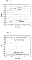
- FIG. 1 is Bark scale plot of roughness of illustrative noise and pure tone input signals as determined in accordance with an aspect of the present invention.
- FIG. 2 is a Bark scale plot of Noise Masking Ratio (NMR) for the illustrative noise and pure tone input signals reflected in FIG. 1, where such NMR plots are determined in accordance with another aspect of the present invention.
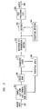
- FIG. 3 is system diagram including a perceptual coder and decoder employing an embodiment of the present invention.
- Present inventive processing of input signals advantageously comprises three main functions: (i) determining the envelope of the part of the audio signal x(t) which is inside a particular cochlea filter band (or so called critical band), (ii) quantifying a roughness measure for the envelope, and (iii) mapping the roughness measure to a NMR for the part of the input signal. This process can then be repeated for determining NMRs of the sginal for each critical band. The analysis and methodology for each of these processing functions will now be explored in turn.
- It has been shown, e.g., in J. Herre and J. D. Johnston, "Enhancing the performance of perceptual audio coding by using temporal noise shaping (TNS)," in 101 st AES Convention, Los Angeles, November 1996, that given a real, time domain signal, x(t), the square of its Hilbert envelope, e(t), can be expressed as

- If X(ƒ) is the Fourier transform of x(t), then(ƒ) is the Fourier transform of its analytic signal, and is a single sided frequency spectrum defined as


- The signal envelope, which corresponds to the part of the signal that is inside a specific cochlea filter band, can be calculated by first filtering(ƒ) of (1) by the cochlea filter, H i (f), i.e.,


- Cochlea bands and filtering are described, e.g., in J. B. Alien, ''Cochlear micromechanics: A physical model of transduction," JASA, vol. 68, no. 6, pp. 1660-1670, 1980; and in J. B. Allen, "Modeling the noise damaged cochlea," in The Mechanics and Biophysics of Hearing (P. Dallos, C. D. Geisler, J. W. Matthews, M. A. Ruggero, and C. R. Steele, eds.), (New York), pp. 324-332, Springer-Verlag, 1991.
- Thus, Eq. (1) can be re-written as:

- In Eq. (4) ei(t) is the square of the signal envelope corresponding to the ith cochlea filter band whose characteristic frequency is ƒi. F 1 in Eq. 4 represents the well-known Inverse Fourier Transform.
- Eq. (1), or Eq. (4), shows that an input audio signal envelope may be derived from the autocorrelation function of its single sided frequency spectrum,(ƒ). This relationship will be seen to be the dual of the following well-known formula which relates the power spectrum density of a signal, S xx (ƒ), to is autocorrelation function in time domain:


- By exploiting this duality, many well-established theories in time domain Linear Prediction (LP) processing can be applied to frequency domain. In particular, one well-known relationship between prediction gain and spectral flatness measure, described, for example, in N. S. Jayant and P. Noll, Digital Coding of Waveforms - Principles and Applications to Speech and Video, page 56. Prentice Hall, 1984, may be used to advantage. In accordance with such teachings, the rougher the frequency-domain spectrum S xx (ƒ), the more predictable is the corresponding time signal x(t); i.e., the higher the prediction gain. (As is well known, prediction gain is defined as the ratio of original signal power to the power of the prediction residual error.)
- Based on the duality of Eqs. (1) and (5), the following conclusion can be made: If linear prediction is applied to coefficients of(ƒ), the single sided spectrum of the time signal x(t), then a higher prediction gain corresponds to a rougher signal envelope e(t). Therefore, for Eq. (4), prediction of
 (ƒ) in the frequency domain serves as a reliable measure of the roughness of the signal envelope, e i (t). For an input signal comprising only white noise, prediction gain of its
 (ƒ) will be the highest among all the signals, since it has the roughest envelope in time domain. On the other hand, prediction gain of
 (ƒ) for pure tones will be the smallest, since they have flat a time domain envelope.
- Linear Prediction (LP) operations are well-known and are described, for example in the above-cited book by Jayant and Noll at page 267. In the context of the present description, the input to LP operations is advantageously chosen as(ƒ), rather than time-domain inputs, as is often the case.

- Roughness of illustrative white noise and pure tone are shown in FIG. 1 on the traditional Bark scale. It should be noted that since the time signal is illustratively windowed by the well-known sin function (thereby increasing the roughness of the flat envelope of a pure tone), roughness of the illustrative pure tone is therefore greater than unity.
- In accordance with an illustrative embodiment of the present invention, mapping a calculated roughness measure for an arbitrary signal to the NMR of the signal is advantageously accomplished using the following steps:
- 1. The calculated roughness measure of an arbitrary signal is normalized by that of a pure tone, since a pure tone has the flatest envelope.
- 2. Square the normalized roughness, since NMR is required in the signal energy domain.
- 3. The value obtained in
step 2 is raised to the 4th power to take into account the effect of the cochlea compression. - The resulting value is then directly proportional to the NMR of the signal. In other words, the signal NMR is calculated as follows:

- The plot of NMRs for white noise shown in FIG. 2 support the accuracy of Eq. (6). That is, it is clear that the resulting NMRs are very close to their theoretical value of -6 dB, as discussed, e.g., in R. P. Hellman, "Asymmetry in masking between noise and tone," Perception and Psychophyics., vol. 11, pp. 241-246, 1972.
- FIG. 3 shows a system organization for an illustrative embodiment of the present invention. In FIG. 3, an analog signal on
input 300 is applied topreprocessor 305 where it is sampled (typically at 44.1 kHz) and each sample is converted to a digital sequence (typically 16 bits) in standard fashion. Of course, if input audio signals are presented in digital form, no such sampling and conversion is required. -
Preprocessor 305 then advantageously groups these digital values in frames (or blocks or sets) of, e.g., 2048 digital values, corresponding to, an illustrative 46 msec of audio input. Other typical values for these and other system or process parameters are discussed in the literature and known in well-known audio processing applications. Also, as is well known in practice, it proves advantageous to overlap contiguous frames, typically to the extent of 50 percent. That is, though each frame contains 2048 ordered digital values, 1024 of these values are repeated from the preceding 2048-value frame. Thus each input digital value appears in two successive frames, first as part of the second half of the frame and then as part of the first half of the frame. Other particular overlapping parameters are well-known in the art. These time-domain signal frames are then transformed infilterbank block 310 using. e.g., a modified discrete cosine transform (MDCT) such as that described in J. Princen, et al., "Sub-band Transform Coding Using Filter Bank Designs Based on Time Domain Aliasing Cancellation," IEEE ICASSP, 1987, pp. 2161-2164. The illustrative resulting set of 1024 real coefficients (zero-frequency, Nyquist frequency, and all intermediate frequencies) resulting from the illustrative MDCT represents the short-term frequency spectrum of the input signal. - These MDCT coefficients are then quantized based on the NMRs calculated, illustratively using the method described above. Thus, by way of illustration:
- 1. For each frame (2048 samples resulted from block 305), calculate the Fourier Transform of its analytic signal, (f) defined in Eq. 2.

- 2. For the ith scale factor band (SFB), calculate (ƒ) using Eq. 3, where the cochlear filter's (H i (ƒ)) characteristic frequency ƒi is the center frequency of this particular scale factor band.

- 3. Perform Linear Prediction on (ƒ) and denote its prediction gain as r s (i).

- 4. Use Eq. 6 to map the roughness of the signal in this SFB, r s (i), to NMR i
- 5. Calculate the average signal power per frequency bin in this SFB, and then multiply it with NMR i to get the scale factor for this SFB.
- 6. Quantize all MDCT coefficients in this SFB using the resulting scale factor.
- 7. Repeat step 2-6 for all SFBs.
- Steps 1-5 illustratively correspond to the
perceptual model block 310. Outputs of this block are scale factors for performing quantization in block 315 (step 6 above). All these scale factors will be sent as side information along with the quantized MDCT coefficients tomedium 320. -
Perceptual model block 310 shown in FIG. 3 includes the perceptual modeling improvements of the present invention described above in illustrative embodiments.Filter bank 308 is shown supplying frequency components for the respective SFB, i, to the quantizer/coder 315 and toperceptual model 310 for calculating the average signal power in the SFB (step 5). The NMR has to be calculated (step 1-5) from the corresponding time signal frame resulted fromblock 305. - Quantizer/
coder block 315 in FIG. 3 represents well-known quantizer-coder structures that respond to perceptual model inputs and frequency components received from a source of frequency domain information, such asfilter bank 308, for an input signal. Quantizer/coder 315 will correspond in various embodiments of the present invention to the well-known AAC coder, but other applications of the present invention may employ various transform or OCF coders and other standards-based coders. -
Block 320 in FIG. 3 represents a recording or transmission medium to which the coded outputs of quantizer/coder 315 are applied. Suitable formatting and modulation of the output signals from quantizer/coder 315 should be understood to be included in themedium block 320. Such techniques are well known to the art and will be dictated by the particular medium, transmission or recording rates and other system parameters. Further, if the medium 320 includes noise or other corrupting influences, it may be necessary to include additional error-control devices or processes, as is well known in the art. Thus, for example, if the medium is an optical recording medium similar to the standard CD devices, then redundancy coding of the type common in that medium can be used with the present invention. If the medium is one used for transmission, e.g., a broadcast, telephone, or satellite medium, then other appropriate error control mechanisms will advantageously be applied. Any modulation, redundancy or other coding to accommodate (or combat the effects of) the medium will, of course, be reversed (or otherwise subject to any appropriate complementary processing) upon the delivery from the channel or other medium 320 to a decoder, such as 330 in FIG. 3. - Coding parameters, including scale factors information used at quantizer/
coder 315 are therefore sent as side information along with quantized frequency coefficients. Such side information is used indecoder 330 andperceptual decoder 340 to reconstruct the original input signal frominput 300 and supply this reconstructed signal onoutput port 360 after performing suitable conversion to time-domain signals, digital-to-analog conversion and any other desired post-processing inunit 350 in FIG. 3. NMR side information is, of course supplied toperceptual decoder 340 for use there in controllingdecoder 330 in restoring uniform quantization of transform (frequency) domain signals suitable for transformation back to the time domain. - The originally coded information provided by quantizer/
coder 315 will therefore be applied at a reproduction device, e.g., a CD player. Output on 360 is in such form as to be perceived by a listener upon playback as substantially identical to that supplied on input 100. - Those skilled in the art will recognize that numerous alternative embodiments of the present invention, and methods of practicing the present invention, in light of the present description.
Where technical features mentioned in any claim are followed by reference signs, those reference signs have been included for the sole purpose of increasing the intelligibility of the claims and accordingly, such reference signs do not have any limiting effect on the scope of each element identified by way of example by such reference signs.
Claims (22)
- A perceptual model for determining Noise Masking Ratios, NMRs, for audio signals x(t) in each cochlea filter band, the method comprising
determining a representation of the envelope of the part of said x(t) that is inside a particular cochlea filter band,
quantifying a roughness measure for said envelope,
mapping said roughness measure to a NMR for the part of the signal that is inside said particular cochlear filter band. - The method of claim 1 wherein said determining a representation of the envelope comprises determining e(t), the square of said envelope.
- The method of claim 1 wherein said determining a representation of said envelope comprises determining(ƒ), where (ƒ) is the Fourier transform of x(t), and
 (ƒ) is the Fourier transform of the analytic signal corresponding to x(t), X (ƒ) being a single sided frequency spectrum defined as

- The method of claim 3 further comprising
filtering said(f) by a cochlear filter, H i (ƒ), for i = 1, 2, ... N to form representations of said single-sided frequency spectrum for N discrete bands of said frequency range, said representations given by

- The method of claim 4 wherein said determining said envelope further comprises determining e i (t) for said N discrete bands in accordance with

- The method of claim 5 wherein said quantifying a roughness measure for said envelope comprises performing a linear prediction of said envelope, e i (t) for each i to determine corresponding banded roughness measures r s (i).
- The method of claim 6 wherein said mapping said roughness measure to a NMR comprises normalizing said r s (i), for each i, with respect to a roughness measure for a pure tone, r t (i), for each i, to form a normalized roughness measure for each i.
- The method of claim 7 wherein said mapping said roughness measure to a NMR further comprises squaring said normalized roughness measure for each i to form a squared roughness measure for each i.
- The method of claim 8 wherein each said squared roughness measure is raised to the 4th power to reflect cochlea compression.
- The method of claim 6 wherein said mapping said/roughness measure for each cochlear band i to a NMR comprises determining

- The method of claim 10 wherein said constant, c, is determined by performing a linear prediction of the envelope, e i (t) for each i for a white noise input signal, thereby determining corresponding banded roughness measures r n (i)
substituting said r n (i) values for r s (i) in
averaging said values of c i for all i to determine said value for c. - A method for coding audio signals x(t) in the frequency domain, the method comprising
for each band of a cochlear filter having a plurality of bands
determining a representation of the envelope of the part of said x(t) that is insi a particular cochlea filter band,
quantifying a roughness measure for said envelope,
mapping said roughness measure to a Noise Masking Ratio, NMR, for the par of x(t) that is inside said particular cochlear filter band,
quantizing said audio signals in the frequency domain using said NMRs to determine quantizing levels. - The method of claim 12 wherein said determining a representation of t envelope comprises determining e(t), the square of said envelope.
- The method of claim 12 wherein said determining a representation of said envelope comprises determining(ƒ), where X(ƒ) is the Fourier transform of x(t), and
 (ƒ) is the Fourier transform of the analytic signal corresponding to x(t),
 (ƒ) being a single sided frequency spectrum defined as

- The method of claim 14 further comprising
filtering said(f) by a cochlear filter, Hi (f), for i = 1, 2, ... N to form representations of said single-sided frequency spectrum for N discrete bands of said frequency range, said representations given by

- The method of claim 15 wherein said determining said envelope comprises determining e i (t) for said N discrete bands in accordance with

- The method of claim 17 wherein said quantifying a roughness measure for said envelope comprises performing a linear prediction of said envelope, e i (t) for each i to determine corresponding banded roughness measures r s (i).
- The method of claim 17 wherein mapping said roughness measure to a NMR comprises normalizing said r s (i), for each i, with respect to a roughness measure for a pure tone, r t (i), for each i, to form a normalized roughness measure for each i.
- The method of claim 18 wherein said mapping said roughness measure to a NMR further comprises squaring said normalized roughness measure for each i to form a squared roughness measure for each i.
- The method of claim 19 wherein each said squared roughness measure is raised to the 4th power to reflect cochlea compression.
- The method of claim 19 wherein said mapping said roughness measure for each cochlear band i to a NMR comprises determining

- The method of claim 21 wherein said constant, c, is determined by performing a linear prediction of the envelope, e i (t) for each i for a white noise input signal, thereby determining corresponding banded roughness measures r n (i)
substituting said r n (i) values for r s (i) in
averaging said values of c i for all i to determine said value for c.
Applications Claiming Priority (2)
| Application Number | Priority Date | Filing Date | Title |
|---|---|---|---|
| US90544 | 2002-03-04 | ||
| US10/090,544 US20100042406A1 (en) | 2002-03-04 | 2002-03-04 | Audio signal processing using improved perceptual model |
Publications (3)
| Publication Number | Publication Date |
|---|---|
| EP1343146A2 true EP1343146A2 (en) | 2003-09-10 |
| EP1343146A3 EP1343146A3 (en) | 2004-07-21 |
| EP1343146B1 EP1343146B1 (en) | 2009-09-16 |
Family
ID=27753988
Family Applications (1)
| Application Number | Title | Priority Date | Filing Date |
|---|---|---|---|
| EP03003261A Expired - Lifetime EP1343146B1 (en) | 2002-03-04 | 2003-02-24 | Audio signal processing based on a perceptual model |
Country Status (4)
| Country | Link |
|---|---|
| US (1) | US20100042406A1 (en) |
| EP (1) | EP1343146B1 (en) |
| CA (1) | CA2419765A1 (en) |
| DE (1) | DE60329248D1 (en) |
Cited By (2)
| Publication number | Priority date | Publication date | Assignee | Title |
|---|---|---|---|---|
| NL1029157C2 (en) * | 2004-06-04 | 2007-10-03 | Samsung Electronics Co Ltd | Audio signal decoding method for e.g. cell-phone, involves generating audio signal by decoding input signal, and transforming original waveform of audio signal into compensation waveform for acoustic resonance effect |
| JP2017078860A (en) * | 2016-10-31 | 2017-04-27 | 株式会社Nttドコモ | Speech coding apparatus and speech coding method |
Families Citing this family (11)
| Publication number | Priority date | Publication date | Assignee | Title |
|---|---|---|---|---|
| SE0202159D0 (en) | 2001-07-10 | 2002-07-09 | Coding Technologies Sweden Ab | Efficientand scalable parametric stereo coding for low bitrate applications |
| WO2003046891A1 (en) | 2001-11-29 | 2003-06-05 | Coding Technologies Ab | Methods for improving high frequency reconstruction |
| SE0202770D0 (en) * | 2002-09-18 | 2002-09-18 | Coding Technologies Sweden Ab | Method of reduction of aliasing is introduced by spectral envelope adjustment in real-valued filterbanks |
| EP1691348A1 (en) * | 2005-02-14 | 2006-08-16 | Ecole Polytechnique Federale De Lausanne | Parametric joint-coding of audio sources |
| JPWO2007037359A1 (en) * | 2005-09-30 | 2009-04-16 | パナソニック株式会社 | Speech coding apparatus and speech coding method |
| US20090138507A1 (en) * | 2007-11-27 | 2009-05-28 | International Business Machines Corporation | Automated playback control for audio devices using environmental cues as indicators for automatically pausing audio playback |
| EP2329399A4 (en) * | 2008-09-19 | 2011-12-21 | Newsouth Innovations Pty Ltd | METHOD FOR ANALYZING AUDIO SIGNAL |
| US8472616B1 (en) * | 2009-04-02 | 2013-06-25 | Audience, Inc. | Self calibration of envelope-based acoustic echo cancellation |
| US9307321B1 (en) | 2011-06-09 | 2016-04-05 | Audience, Inc. | Speaker distortion reduction |
| WO2014112110A1 (en) * | 2013-01-18 | 2014-07-24 | 株式会社東芝 | Speech synthesizer, electronic watermark information detection device, speech synthesis method, electronic watermark information detection method, speech synthesis program, and electronic watermark information detection program |
| CN113395637B (en) * | 2021-06-10 | 2022-09-09 | 上海傅硅电子科技有限公司 | A method for controlling the output voltage of an audio power amplifier chip |
Family Cites Families (7)
| Publication number | Priority date | Publication date | Assignee | Title |
|---|---|---|---|---|
| US4631747A (en) * | 1978-07-17 | 1986-12-23 | Raytheon Company | Digital sound synthesizer |
| US5040217A (en) * | 1989-10-18 | 1991-08-13 | At&T Bell Laboratories | Perceptual coding of audio signals |
| US5285498A (en) * | 1992-03-02 | 1994-02-08 | At&T Bell Laboratories | Method and apparatus for coding audio signals based on perceptual model |
| JPH08190764A (en) * | 1995-01-05 | 1996-07-23 | Sony Corp | Digital signal processing method, digital signal processing device and recording medium |
| US5956674A (en) * | 1995-12-01 | 1999-09-21 | Digital Theater Systems, Inc. | Multi-channel predictive subband audio coder using psychoacoustic adaptive bit allocation in frequency, time and over the multiple channels |
| US6466912B1 (en) * | 1997-09-25 | 2002-10-15 | At&T Corp. | Perceptual coding of audio signals employing envelope uncertainty |
| US6115689A (en) * | 1998-05-27 | 2000-09-05 | Microsoft Corporation | Scalable audio coder and decoder |
-
2002
- 2002-03-04 US US10/090,544 patent/US20100042406A1/en not_active Abandoned
-
2003
- 2003-02-24 DE DE60329248T patent/DE60329248D1/en not_active Expired - Lifetime
- 2003-02-24 EP EP03003261A patent/EP1343146B1/en not_active Expired - Lifetime
- 2003-02-25 CA CA002419765A patent/CA2419765A1/en not_active Abandoned
Cited By (2)
| Publication number | Priority date | Publication date | Assignee | Title |
|---|---|---|---|---|
| NL1029157C2 (en) * | 2004-06-04 | 2007-10-03 | Samsung Electronics Co Ltd | Audio signal decoding method for e.g. cell-phone, involves generating audio signal by decoding input signal, and transforming original waveform of audio signal into compensation waveform for acoustic resonance effect |
| JP2017078860A (en) * | 2016-10-31 | 2017-04-27 | 株式会社Nttドコモ | Speech coding apparatus and speech coding method |
Also Published As
| Publication number | Publication date |
|---|---|
| US20100042406A1 (en) | 2010-02-18 |
| DE60329248D1 (en) | 2009-10-29 |
| EP1343146A3 (en) | 2004-07-21 |
| EP1343146B1 (en) | 2009-09-16 |
| CA2419765A1 (en) | 2003-09-04 |
Similar Documents
| Publication | Publication Date | Title |
|---|---|---|
| Carnero et al. | Perceptual speech coding and enhancement using frame-synchronized fast wavelet packet transform algorithms | |
| CN107925388B (en) | Post processor, pre processor, audio codec and related method | |
| US7110953B1 (en) | Perceptual coding of audio signals using separated irrelevancy reduction and redundancy reduction | |
| CN100589657C (en) | Method and device for economizing loudness measurement of encoded audio | |
| US6934677B2 (en) | Quantization matrices based on critical band pattern information for digital audio wherein quantization bands differ from critical bands | |
| RU2734781C1 (en) | Device for post-processing of audio signal using burst location detection | |
| EP2186087B1 (en) | Improved transform coding of speech and audio signals | |
| EP0720148B1 (en) | Method for noise weighting filtering | |
| EP2207169B1 (en) | Audio decoding with filling of spectral holes | |
| EP0446037B1 (en) | Hybrid perceptual audio coding | |
| Spanias et al. | Analysis of the MPEG-1 Layer III (MP3) algorithm using MATLAB | |
| KR102105305B1 (en) | Method and apparatus for encoding and decoding audio signal using layered sinusoidal pulse coding | |
| EP1343146B1 (en) | Audio signal processing based on a perceptual model | |
| HK1002743B (en) | Hybrid perceptual audio coding | |
| Erne | Perceptual audio coders" what to listen for" | |
| EP1517300B1 (en) | Encoding of audio data | |
| Malah et al. | Performance of transform and subband coding systems combined with harmonic scaling of speech | |
| US6678647B1 (en) | Perceptual coding of audio signals using cascaded filterbanks for performing irrelevancy reduction and redundancy reduction with different spectral/temporal resolution | |
| Sen et al. | Use of an auditory model to improve speech coders | |
| Virette | Low Delay Transform for High Quality Low Delay Audio Coding | |
| Heute | Speech and audio coding—aiming at high quality and low data rates | |
| Nemer et al. | Perceptual Weighting to Improve Coding of Harmonic Signals | |
| Pollak et al. | Audio Compression using Wavelet Techniques | |
| Ruan | Lapped transforms in perceptual coding of wideband audio | |
| Trinkaus et al. | An algorithm for compression of wideband diverse speech and audio signals |
Legal Events
| Date | Code | Title | Description |
|---|---|---|---|
| PUAI | Public reference made under article 153(3) epc to a published international application that has entered the european phase |
Free format text: ORIGINAL CODE: 0009012 |
|
| AK | Designated contracting states |
Kind code of ref document: A2 Designated state(s): AT BE BG CH CY CZ DE DK EE ES FI FR GB GR HU IE IT LI LU MC NL PT SE SI SK TR |
|
| AX | Request for extension of the european patent |
Extension state: AL LT LV MK RO |
|
| PUAL | Search report despatched |
Free format text: ORIGINAL CODE: 0009013 |
|
| RIC1 | Information provided on ipc code assigned before grant |
Ipc: 7H 04B 1/66 B Ipc: 7G 10L 19/02 A |
|
| AK | Designated contracting states |
Kind code of ref document: A3 Designated state(s): AT BE BG CH CY CZ DE DK EE ES FI FR GB GR HU IE IT LI LU MC NL PT SE SI SK TR |
|
| AX | Request for extension of the european patent |
Extension state: AL LT LV MK RO |
|
| 17P | Request for examination filed |
Effective date: 20050119 |
|
| AKX | Designation fees paid |
Designated state(s): DE FI FR GB NL SE |
|
| 17Q | First examination report despatched |
Effective date: 20050623 |
|
| 17Q | First examination report despatched |
Effective date: 20050623 |
|
| GRAP | Despatch of communication of intention to grant a patent |
Free format text: ORIGINAL CODE: EPIDOSNIGR1 |
|
| GRAS | Grant fee paid |
Free format text: ORIGINAL CODE: EPIDOSNIGR3 |
|
| GRAA | (expected) grant |
Free format text: ORIGINAL CODE: 0009210 |
|
| AK | Designated contracting states |
Kind code of ref document: B1 Designated state(s): DE FI FR GB NL SE |
|
| REG | Reference to a national code |
Ref country code: GB Ref legal event code: FG4D |
|
| REF | Corresponds to: |
Ref document number: 60329248 Country of ref document: DE Date of ref document: 20091029 Kind code of ref document: P |
|
| REG | Reference to a national code |
Ref country code: SE Ref legal event code: TRGR |
|
| PLBE | No opposition filed within time limit |
Free format text: ORIGINAL CODE: 0009261 |
|
| STAA | Information on the status of an ep patent application or granted ep patent |
Free format text: STATUS: NO OPPOSITION FILED WITHIN TIME LIMIT |
|
| 26N | No opposition filed |
Effective date: 20100617 |
|
| PGFP | Annual fee paid to national office [announced via postgrant information from national office to epo] |
Ref country code: SE Payment date: 20110209 Year of fee payment: 9 Ref country code: DE Payment date: 20110228 Year of fee payment: 9 Ref country code: NL Payment date: 20110216 Year of fee payment: 9 Ref country code: FI Payment date: 20110128 Year of fee payment: 9 Ref country code: FR Payment date: 20110201 Year of fee payment: 9 |
|
| PGFP | Annual fee paid to national office [announced via postgrant information from national office to epo] |
Ref country code: GB Payment date: 20110124 Year of fee payment: 9 |
|
| REG | Reference to a national code |
Ref country code: NL Ref legal event code: V1 Effective date: 20120901 |
|
| GBPC | Gb: european patent ceased through non-payment of renewal fee |
Effective date: 20120224 |
|
| PG25 | Lapsed in a contracting state [announced via postgrant information from national office to epo] |
Ref country code: FI Free format text: LAPSE BECAUSE OF NON-PAYMENT OF DUE FEES Effective date: 20120224 Ref country code: SE Free format text: LAPSE BECAUSE OF NON-PAYMENT OF DUE FEES Effective date: 20120225 |
|
| REG | Reference to a national code |
Ref country code: FR Ref legal event code: ST Effective date: 20121031 |
|
| REG | Reference to a national code |
Ref country code: DE Ref legal event code: R119 Ref document number: 60329248 Country of ref document: DE Effective date: 20120901 |
|
| PG25 | Lapsed in a contracting state [announced via postgrant information from national office to epo] |
Ref country code: GB Free format text: LAPSE BECAUSE OF NON-PAYMENT OF DUE FEES Effective date: 20120224 Ref country code: NL Free format text: LAPSE BECAUSE OF NON-PAYMENT OF DUE FEES Effective date: 20120901 Ref country code: FR Free format text: LAPSE BECAUSE OF NON-PAYMENT OF DUE FEES Effective date: 20120229 |
|
| PG25 | Lapsed in a contracting state [announced via postgrant information from national office to epo] |
Ref country code: DE Free format text: LAPSE BECAUSE OF NON-PAYMENT OF DUE FEES Effective date: 20120901 |