EP1343118A2 - Bewegungsbildererzeugungsgerät -program und -verfahren - Google Patents
Bewegungsbildererzeugungsgerät -program und -verfahren Download PDFInfo
- Publication number
- EP1343118A2 EP1343118A2 EP03012223A EP03012223A EP1343118A2 EP 1343118 A2 EP1343118 A2 EP 1343118A2 EP 03012223 A EP03012223 A EP 03012223A EP 03012223 A EP03012223 A EP 03012223A EP 1343118 A2 EP1343118 A2 EP 1343118A2
- Authority
- EP
- European Patent Office
- Prior art keywords
- plot information
- plot
- information generating
- image
- plotting
- Prior art date
- Legal status (The legal status is an assumption and is not a legal conclusion. Google has not performed a legal analysis and makes no representation as to the accuracy of the status listed.)
- Withdrawn
Links
- 238000000034 method Methods 0.000 title claims description 99
- 239000000203 mixture Substances 0.000 title claims description 44
- 230000008569 process Effects 0.000 claims description 91
- 230000006870 function Effects 0.000 description 64
- 230000015654 memory Effects 0.000 description 40
- 230000008859 change Effects 0.000 description 9
- 238000004364 calculation method Methods 0.000 description 8
- 230000010365 information processing Effects 0.000 description 4
- 239000000470 constituent Substances 0.000 description 2
- 239000000284 extract Substances 0.000 description 2
- 230000004048 modification Effects 0.000 description 2
- 238000012986 modification Methods 0.000 description 2
- 230000003287 optical effect Effects 0.000 description 2
- 230000003466 anti-cipated effect Effects 0.000 description 1
- 238000012217 deletion Methods 0.000 description 1
- 230000037430 deletion Effects 0.000 description 1
- 238000012545 processing Methods 0.000 description 1
- 230000009467 reduction Effects 0.000 description 1
- 230000008521 reorganization Effects 0.000 description 1
- 238000013519 translation Methods 0.000 description 1
Images

Classifications
-
- G—PHYSICS
- G06—COMPUTING; CALCULATING OR COUNTING
- G06T—IMAGE DATA PROCESSING OR GENERATION, IN GENERAL
- G06T13/00—Animation
-
- G—PHYSICS
- G06—COMPUTING; CALCULATING OR COUNTING
- G06T—IMAGE DATA PROCESSING OR GENERATION, IN GENERAL
- G06T11/00—2D [Two Dimensional] image generation
- G06T11/60—Editing figures and text; Combining figures or text
Definitions
- the present invention relates to a moving image composition apparatus for combining one or more moving images (referred to below as dynamic images) and displaying them on a screen, and a program and a method thereof.
- reproduction software has a function to combine and store both the data of an image component to be displayed and the data of the movement and to transmit the combined data to a plotting device when the image is reproduced.
- the conventional reproduction software As described above, in the conventional reproduction software, a great amount of movement data must be prepared to represent many complex movements. A new movement cannot also be composed when an image is reproduced, nor can a movement also be flexibly modified. Furthermore, the conventional reproduction software has a problem that there is no method for sharing the same movement element with a plurality of image components.
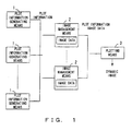
- Fig. 1 shows the basic configuration of the dynamic image (moving image) composition apparatus of the present invention.
- the dynamic image composition apparatus shown in Fig. 1 comprises a plurality of plot information generating means 1, one or more image management means 2 and a plotting means 3, and it combines and displays one or more images.
- Each plot information generating means 1 generates plot information (plotting information) used to plot a dynamic image (moving image).
- Each image management means 2 manages (stores) the image data of each image and generates the plot information at a present time of each image by combining one or more pieces of plot information generated by one or more of a plurality of plot information generating means 2.
- the plotting means 3 receives both the image data and plot information at a present time from the image management means 2 and plots (reproduces) the image data based on the plot information at a present time.
- the plot information are generated for each image and includes information about the position coordinates on a screen of an image.
- each of the plurality of plot information generating means 1 When an image is reproduced, each of the plurality of plot information generating means 1 generates plot information for plotting a different movement element, and the image management means 2 generates one piece of plot information by combining a plurality of pieces of plot information generated by the plurality of plot information generating means 1.
- first and second plot information generating means generate plot information for indicating the vertical vibration of a sine wave and plot information for indicating the rightward shift, respectively, plot information obtained by combining those pieces of plot information indicates a rightward shift with a vertical vibration along the locus of a sine wave.
- the plotting means 3 plots image data based on the plot information composed in this way and represents a composed movement. If there are a plurality of image management means 2, the plotting means 3 plots the image data based on plot information corresponding to each piece of image data and combines a plurality of images on a screen.
- a complex movement can be easily generated by combining a plurality of pieces of plot information generated by a plurality of plot information generating means 1, in real time when an image is reproduced. Since the plurality of image management means 2 can use one plot information generating means 1, one movement element can be used to plot a plurality of different images.
- a plot information generating means 1 can also be handled as a movement component for plotting an individual movement, and a plot information generating means 1 can also be added/deleted according to an event generated while a dynamic image is reproduced. Therefore, the movement of an image can be modified by a user's input operation, etc.
- the plot information generating means 1 shown in Fig. 1 corresponds to the plot information generating unit 23 shown in Fig. 2 and the plot information generating unit 41 shown in Fig. 4, which are both described later.
- the image management means 2 corresponds to the image management unit 11 shown in Fig. 2.
- the plotting means 3 corresponds to the plotting unit 12, VRAM (video random access memory) 13 and display 14 which are shown in Fig. 2.
- a plurality of plot information generation units are provided for each image component, and the movement of each image component is composed in real time when an image is reproduced.
- the position, size, rotation angle, color, sequential relationship, etc., of an image component are used, and the movement of each image component can be determined by providing plot information at each time.
- a complex movement can be easily generated by combining in real time a plurality of pieces of plot information generated by the plurality of plot information generating units.
- a movement element can be widely used by enabling the same movement element to be referred by a plurality of plot information generating units.
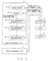
- Fig. 2 shows the configuration of a dynamic image composition apparatus based on absolute plot information.
- the dynamic image composition apparatus shown in Fig. 2 comprises one or more image management units 11, a plotting unit 12, a VRAM 13 and a display 14.
- the image management unit 11 is provided for each image component, and, for example, it passes both image data and plot information at a present time to the plotting unit 12 at appropriate intervals, such as once per frame, etc., or at dynamically determined intervals.
- the plotting unit 12 writes the image data, received from each image management unit 11, in the VRAM 13 based on the plot information and displays the data on the screen of the display 14.
- the image management unit 11 includes an image source 21, a memory 22 and one or more plot information generating units 23.
- the image source 21 is, for example, a still image memory, a motion picture decoder, etc., and it generates image data to be written in the VRAM 13. Therefore, the data in the image source 21 include arbitrary images, such as a still image, motion picture, character, symbol, etc.
- the plot information generating units 23 are linked to one another in an order relation. Each plot information generating unit 23 calculates the absolute plot information at a present time according to a corresponding movement element, adds the calculation result at a present time to the plot information passed by a higher-order plot information generating unit 23 and passes the information to a lower-order plot information generating unit 23.
- the highest-order plot information generating unit 23 reads the plot information at a previous time from the memory 22, calculates plot information at a present time based on the information and passes the information to a lower-order plot information generating unit 23.
- the plot information at a present time outputted by the lowest-order plot information generating unit 23 is passed to the plotting unit 12 and is simultaneously written in the memory 22.
- the order, type and number of the plot information generating units can be fixed or can be dynamically changed according to time, by a user's operation, etc.
- the plot information generating unit 23 can be configured by software or hardware.
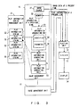
- the dynamic image composition apparatus shown in Fig. 2 can be implemented, for example, by the configuration shown in Fig. 3.
- the dynamic image composition apparatus shown in Fig. 3 further comprises a plot information string management unit 31 in addition to the constituent components shown in Fig. 2.
- the plot information string management unit 31 stores one or more plot information strings 32, and these plot information strings 32 are identified by identifiers (indexes).
- the plot information string 32 is a list of a plurality of pieces of plot information at arbitrarily discrete times, and it describes respective pieces of plot information at each time of, for example, 0, 10, 60 and 65 seconds.
- Each plot information generating unit 23 stores both an identifier 33 for referring to the plot information string 32 and a modification parameter 34 for modifying plot information. At a specific time, the plot information generating unit 23 extracts two pieces of plot information before and after the time from the plot information string 32 in the plot information string management unit 31 corresponding to the identifier 33. Then, the plot information generating unit 23 calculates plot information at a present time by a method of performing interpolation using the extracted plot information, etc.
- the plot information generating unit 23 enlarges or reduces the calculated plot information by the parameter 34, adds the calculation result at a present time to the plot information passed by a higher-order plot information generating unit 23 and passes the information to a lower-order plot information generating unit 23.
- the parameter 34 can be not only applied to plot information itself, but it can also be applied to a time when the plot information is extracted. By changing a time in this way, the movement speed of an image can be changed.
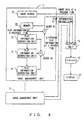
- Fig. 4 shows a dynamic image composition apparatus based on the difference between two pieces of plot information.
- the dynamic image composition apparatus shown in Fig. 4 comprises one or more image management units 11, a plotting unit 12, a VRAM 13 and a display 14 like the dynamic image composition apparatus shown in Fig. 2.
- the image management unit 11 includes an image source 21, a memory 22, one or more plot information generating units 41 and adders 42 and 43.
- Each plot information generating unit 41 calculates the difference in plot information (difference plot information) between a previous time and a present time according to a corresponding movement element, and adds the difference to the adder 43.
- the adder 43 totals a plurality of pieces of the difference plot information at a present time outputted by the plot information generating units 41, and the adder 42 obtains plot information at a present time by adding the totaled difference plot information at a present time to plot information at a previous time read from the memory 22.
- the plot information at a present time outputted from the adder 42 is passed to the plotting unit 12 and is simultaneously stored in the memory 22.
- the type and number of the plot information generating units 41 can be fixed or can be dynamically changed according to time, by a user's operation, etc.
- the operational order of the plot information generating units 41 does not have to be specially designated and they can also be operated in parallel.
- the plot information generating units 41 can be configured by software or hardware.
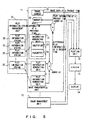
- the dynamic image composition apparatus shown in Fig. 4 can be implemented, for example, by a configuration, as shown in Fig. 5.
- the dynamic image composition apparatus shown in Fig. 5 further comprises the plot information string management unit 31 shown in Fig. 3 in addition to the constituent components shown in Fig. 4.
- Each plot information generating unit 41 stores both an identifier 33 for referring to the plot information string 32 and a modification parameter 34 for modifying plot information like the plot information generating unit 23 shown in Fig. 3.
- the plot information generating unit 41 calculates difference plot information at a present time by a method of performing interpolation based on the plot information extracted from the plot information string management unit 31 using the identifier 33, etc. Then, the plot information generating unit 41 enlarges or reduces the calculated difference plot information by the parameter 34 and outputs the calculation result to the adder 43.
- the data of the image source 21, the data of the plot information string management unit 31, the programs of the plot information generating units 23 and 41, the program of the plotting unit 12, etc. are already read and expanded in the memory of a computer.
- the image source 21 is an MPEG (Moving Picture Experts Group) decoder, motion picture data after image expansion are read into the memory.
- the plotting unit 12 stores a variable in order to receive an event notice from another event control unit, such as an event loop, etc.
- an event control unit such as an event loop, etc.
- an arbitrary form such as a user's input operation, interruption by the system, etc., and the event is not limited to a specific form.
- plot information two-dimensional coordinates corresponding to the position at which an image is displayed are used, the same fundamental algorithm can also be applied, even if other plot information, such as the size, rotation angle, etc., of an image is used.
- plot information string 32 Although for the data included in the plot information string 32, an identifier, time and two-dimensional coordinate string are used, the overall algorithm does not change, even if information indicating a more complex movement is included. Since the plot information generating units 23 and 41 store respective unique internal times and coordinate spaces, different movements can be represented by one plot information string 32.
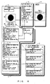
- Fig. 6 shows a dynamic image composition process in the case where a plot information function is used instead of the plot information string 32 in the configuration shown in Fig. 3.
- the plot information function management unit 51 shown in Fig. 6 stores one or more plot information functions 52 in the form of a list, and these plot information functions 52 can be identified by identifiers.
- the plotting unit 12 stores a list 61 of pointers to an arbitrary number of image management units 11, a variable 62 for receiving an event notice and an image update interval 63.
- each plot information generating unit 23 can refer to an arbitrary information function 52. Therefore, one plot information function 52 can sometimes be referred by a plurality of plot information generating units 23 in one image management unit 11 and can sometimes be referred by the respective plot information generating units 23 in a plurality of image management units 11.
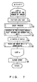
- Fig. 7 is a flowchart showing the plot update process of the dynamic image composition apparatus shown in Fig. 6.
- M pieces of image data 64 of image management units #1-#M are sequentially plotted on coordinates generated via plot information generating units #1-#N by one plot update process.
- a loop a corresponds to a process of calling up each plot management unit 11 and the process is repeated M times.
- the image management unit 11 assigns the last plot coordinates (x_last, y_last) at a previous time to plot coordinates (x, y) (step S1) and it performs an event process (step S2).
- event process event information which is notified to the plotting unit 12 during an update interval dt and stored in a variable Event, is identified and the plot information generating units 23 are dynamically reorganized, if required. The details of this event process are described later.
- the highest-order plot information generating unit #1 is called up and the change of the plot coordinates during the update interval dt is calculated (step S3).
- the units are recurrently called up and plot coordinates (x, y) outputted by the lowest-order plot information generating unit #N are passed to the plotting unit 12 as plot coordinates at a present time. The details of this plot information generating process are described later.
- the image management unit 11 assigns the obtained coordinates (x, y) to coordinates (x_last, y_last) (step S4), and the plotting unit 12 plots the image data 64 at the position of the coordinates (x, y) (step S5).
- the plotting unit 12 clears the variable Event in order to receive a new event notice (step S6) and terminates the process.
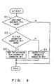
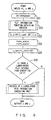
- Fig. 8 is a flowchart showing the event process in step S2 shown in Fig. 7.
- the event information stored in the variable Event of the plotting unit 12 includes both the identifier of the image data 64 and a flag indicating that a new plot information generating unit 23 should be generated or that an existing plot information generating unit 23 should be deleted.
- the event information also includes additional information for designating a plot information generating unit 23 to be generated/deleted.
- the image management unit 11 judges from the identifier whether the image data 64 being processed are the target of the event notice (step S11). If the image data 64 being processed are not the target, the image management unit 11 terminates the process. If the image data are the target, the image management unit 11 adds/deletes a plot information generating unit 23 using both the flag and additional information.
- the image management unit 11 judges whether the flag indicates the addition of a plot information generating unit (step S12). If it is judged that the flag indicates the addition, the image management unit 11 adds a plot information generating unit 23 designated by the additional information (step S13) and terminates the process. If it is judged that the flag does not indicates the addition, the image management unit 11 deletes a plot information generating unit 23 designated by the additional information (step S14) and terminates the process.
- the addition/deletion of a plot information generating unit 23 can be implemented, for example, by adding data to the list of plot information generating units 23 stored by the image management unit 11 and deleting data from the list. At this time, pointers between plot information generating units 23 are reorganized, if required.
- the complex movement of an image can be dynamically changed by such a dynamic reorganization process of plot information generating units 23. For example, by deleting a plot information generating unit 23 only for a single vibration or only for a parallel shift from the image management unit 11 for an image which is obtained by combining the single vibration and parallel shift and which moves in the form of a sine wave, the present movement of the image can be transferred to another simpler movement. By adding a plot information generating unit 23 for single vibration to the image management unit 11 of an image which moves in parallel, the present movement of the image can be transferred to another more complex movement.
- Fig. 9 is a flowchart showing the plot information generating process in step S3 shown in Fig. 7.
- the highest-order plot information generating unit #1 executes a process using both an update interval dt and plot coordinates (x, y) as inputs, and outputs updated plot coordinates (x, y).
- the plot information generating unit #1 first multiplies the update interval dt by a parameter speed1 to convert a global update interval dt to the internal update interval dt1 of the plot information generating unit #1 (step S21).
- Equation (1) indicates that x and y are calculated as functions of t_last1, dt1, x and y.
- x and y are multiplied by a parameter x_scalel and y_scale1, respectively, and the results are assigned to x and y, respectively (step S24).
- the plot information generating unit #1 calls up the lower-order plot information generating unit 23, provides the lower-order plot information generating unit 23 with both the update interval dt and obtained plot coordinates (x, y) as inputs and makes the lower-order plot information generating unit 23 execute the same plot information generating process (step S27).
- the plot information generating process shown in Fig. 9 is recurrently called up and the process of a plot information generating unit #i is executed.
- (x, y) fk(t_lasti, dt1, x, y)
- step S26 there is a lower-order plot information generating unit 23
- the plot information generating unit #i calls up the lower-order plot information generating unit 23. If there is no lower-order plot information generating unit 23, the plot information generating unit #i outputs the obtained plot coordinates (x, y) to the original higher-order plot information generating unit 23 and terminates the process.
- the higher-order plot information generating unit 23 On receipt of the plot coordinates from the lower-order plot information generating unit 23, the higher-order plot information generating unit 23 sequentially passes the plot coordinates to other higher-order plot information generating units 23 and the highest plot information generating unit #1 outputs the received plot coordinates as the result of one update process.
- a plurality of plot information generated by a plurality of pieces of plot information generating units 23 can be combined in real time and they can be supplied to the plotting unit 12. Therefore, the complex movement of an image can be easily generated by automatically repeating the update of the image.
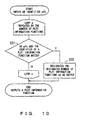
- Fig. 10 is a flowchart showing the plot information function obtaining process in step S22 shown in Fig. 9.
- the plot information generating unit #i passes the identifier pfk to the plot information function management unit 51
- the plot information function management unit 51 executes the loop a process. Loop a is repeated K times in correspondence with the number of plot information functions.
- the plot information function management unit 51 compares the inputted identifier pfk with the identifier of one plot information function 52 (step S31). If the identifiers match, the plot information function management unit 51 outputs a plot information function 52 corresponding to the identifier pfk (step S32) and terminates the process. If the identifiers do not match, the plot information function management unit 51 repeats a process of comparing the identifier pfk with the identifier of a subsequent plot information function 52.
- Fig. 11 shows a dynamic image composition process in the case where the configuration shown in Fig. 3 is used.
- the plot information string management unit 31 shown in Fig. 11 stores one or more plot information strings 32 in the form of a list, and these plot information strings 32 are identified by identifiers.
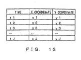
- Each plot information string 32 includes a string of discrete times and plot coordinate values.
- the list 61, event variable 62 and update interval 63 of the plotting unit 12, and the image data 64, last plot coordinates 65 and plot coordinates 66 of the image management unit 11 are the same as those shown in Fig. 6.
- each plot information generating unit 23 can refer to an arbitrary plot information string 32. Therefore, one plot information string 32 can sometimes be referred by a plurality of plot information generating units 23 in one image management unit 11 and can sometimes be referred by the respective plot information generating units 23 in a plurality of image management units 11.
- the plot information generating unit #i stores a difference calculation flag bDiffi as one of the parameters.
- the plot information generating unit #i adds a difference to inputted plot coordinates and outputs the coordinates if this bDiffi value is true, and it outputs absolute plot coordinates regardless of inputted plot coordinates if the b Diffi value is false.
- the plot update process of the dynamic image composition apparatus shown in Fig. 11 is basically the same as that shown in Fig. 7. However, in step S3 shown in Fig. 7, the highest-order plot information generating unit #1 executes the plot information generating process shown in Fig. 12 using both an update interval dt and plot coordinates (x, y) as inputs and it outputs the updated plot coordinates (x, y).
- the plot information generating unit #1 first converts the update interval dt to an internal update interval dt1 by multiplying the update interval dt by a parameter speed1 (step S41) and obtains a plot information string corresponding to a plot information string identifier ID1 (step S42). This plot information string obtaining process is described later.
- the plot information generating unit #1 obtains coordinate values at times before and after t_last1 and t_last1+dt1, and calculates the coordinate change difference (dx, dy) between t_last1 and t_last1+dt1 by interpolation using those coordinate values (step S43).
- This difference (dx, dy) corresponds to the movement amount of an image during the internal update interval dt1.
- the difference (dx, dy) is calculated as follows. However, it is assumed that t1 ⁇ t2 ⁇ t3 ⁇ ... ⁇ tJ is satisfied, x1, x2, x3, ..., xJ are different and y1, y2, y3, ..., yJ are different.
- dx (x2-x1)*(t2-t_last1)/(t2 - t1) +xj-x2 +(x(j+1)-xj)*(t_last1+dt1-tj)/(t(j+1)-tj)
- dy (y2-y1)*(t2-t_last1)/(t2-t1) +yj-y2 +(y(j+1)-yj)*(t_last1+dt1-tj)/(t(j+1)-tj)
- equations (3), (4), (5) and (6) are an example of linear interpolation, a more complex interpolation method can also be used when a difference (dx, dy) is obtained from plot information string data.
- the plot information generating unit #1 multiplies coordinates dx and dy by parameters x_scale1 and y_scale1, respectively, and assigns the results to coordinates dx and dy, respectively (step S44). Then, the plot information generating unit #1 judges the value of the difference calculation flag b Diff1 (step S45).
- the plot information generating unit #1 adds the difference (dx, dy) to inputted plot coordinates (x, y) and assigns the result to the coordinates (x, y) (step S46). If the value of the flag bDiff1 is false, the plot information generating unit #1 assigns the difference (dx, dy) to the coordinates (x, y) with no addition (step S47). In this case, the inputted plot coordinates (x, y) are cancelled and new coordinates (x, y) are generated.
- the plot information generating unit #1 calls up the lower-order information generating unit 23, provides the lower-order information generating unit 23 with both the update interval dt and obtained plot coordinates (x, y) as inputs and makes the lower-order information generating unit 23 execute the same plot information generating process (step S50).
- the plot information generating process shown in Fig. 12 is recurrently called up and the process of the plot information generating unit #i is executed.
- step S49 there is a lower-order plot information generating unit 23
- the plot information generating unit #i calls up the lower-order plot information generating unit 23. If there is no lower-order plot information generating unit 23, the plot information generating unit #i outputs the plot coordinates (x, y) to the original higher-order plot information generating unit 23 and terminates the process.
- the higher-order plot information generating unit 23 On receipt of the plot coordinates from the lower-order plot information generating unit 23, the higher-order plot information generating unit 23 sequentially passes the plot coordinates to another higher-order plot information generating unit 23.
- the highest-order plot information generating unit #1 outputs the received plot coordinates as a result of one update process.
- the plot information generating unit 23 can generate plot information using a plot information string instead of a plot information function.
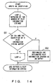
- Fig. 14 is a flowchart showing the plot information string obtaining process in step S42 shown in Fig. 12.
- the plot information generating unit #i passes the identifier IDk to the plot information string management unit 31, the plot information string management unit 31 executes a loop a process. Loop a is repeated K times corresponding to the number of the plot information strings 32.
- the plot information string management unit 31 compares the inputted identifier IDk with the identifier of one plot information string 32 (step S51). If the identifiers match, the plot information string management unit 31 outputs a plot information string 32 corresponding to the identifier IDk (step S52), and terminates the process. If the identifiers do not match, the plot information string management unit 31 repeats the process of comparing the identifier IDk with the identifier of a subsequent plot information string 32.
- each plot information generating unit 23 can cancel plot information passed from a higher-order plot information generating unit 23 and can generate a new piece of plot information. Therefore, for example, the movement of an image can also be stopped at a specific predetermined time.
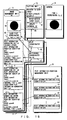
- plot information generating unit 23 generates absolute plot information using the plot information from a higher-order plot information generating unit 23 as an input, plot information outputted from the image management unit 11 is affected by the operation order of the plot information generating unit 23.
- the image management unit 11 includes two plot information generating units #1 and #2
- the plot information generating unit #1 generates the plot information about a vertical vibration on a screen
- the plot information generating unit #2 generates plot information which moves rightward between time 0 and time t1 and stops at time t1.
- the plot information generating units #1 and #2 are operated in that order. Lastly, plot information of an image which moves rightward while vertically vibrating between times 0 and t1 and stops there at and after time t1, is outputted. If the plot information generating units #2 and #1 are operated in that order, lastly, plot information of an image which moves rightward while vertically vibrating between times 0 and t1 and it vertically vibrates there at and after time t1, is outputted. Therefore, the composition movement differs depending on the operation order of the plot information generating units #1 and #2.
- Fig. 15 shows the dynamic image composition process in the case where a plot information function 52 is used instead of a plot information string 32 in the configuration shown in Fig. 5.
- the pointer list 61, event variable 62 and update interval 63 of the plotting unit 12; the image data 64, last plot coordinates 65 and plot coordinates 66 of the image management unit 11; information stored in the plot information generating units 41; and the plot information function management 51 which are all shown in Fig. 15 are the same as those shown in Fig. 6.
- Each image management unit 11 also stores difference coordinates 67 and further stores one or more plot information generating units 41 in the form of a list.
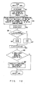
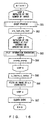
- Fig. 16 is a flowchart showing the plot update process of the dynamic image composition apparatus shown in Fig. 15.
- M pieces of image data of the image management units #1-#M are sequentially plotted on coordinates generated by the plot information generating units #1-#N.
- a loop a corresponds to a process of calling up each image management unit 11 and is repeated M times.
- a loop b corresponds to a process of calling up each plot information generating unit 41 and is repeated N times.
- the image management unit 11 executes the event process shown in Fig. 8 (step S61), assigns the last plot coordinates (x_last, y_last) at a previous time to plot coordinates (x, y) (step S62) and executes the process of loop b.
- step S63 the plot information generating unit 41 is called up, and coordinate change difference (dx, dy) during an update interval dt is calculated (step S63). The details of this plot information generating process are described later. Then, the obtained difference (dx, dy) is added to the plot coordinates (x, y), and the result is assigned to the plot coordinates (x, y) (step S64).
- lower-order plot information generating units #(i+1) can be sequentially called up tracing a pointer 1pi from the highest-order plot information generating unit #1 or the plot information generating units #1-#N can be operated in parallel.
- the image management unit 11 assigns the obtained coordinates (x, y) to coordinates (x_last, y_last) (step S65), and the plotting unit 12 plots the image data 64 at the position of the plot coordinates (x, y) (step S66).
- the plotting unit 12 clears the variable Event to receive a new event notice (step S67) and terminates the process.
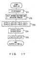
- Fig. 17 is a flowchart showing the plot information generating process in step S63 shown in Fig. 16.
- the plot information generating unit #i executes a process using an update interval dt as an input and outputs a plot coordinate difference (dx, dy).
- the plot information generating unit #i first multiplies the update interval dt by a parameter speedi and converts the update interval dt to an internal update interval dt1 (step S71). Then, the plot information generating unit #i obtains a plot information function fk(t) corresponding to a plot information function identifier pfk from the plot information function management unit 51 by executing the plot information function obtaining process shown in Fig. 10 (step S72).
- fk(t) is expressed by the following equation.
- fk(t) (fkx(t), fky(t))
- the plot information generating unit #i calculates the difference (dx, dy) according to the following equation using both an internal time t_last1 calculated at a previous time and the internal update interval dt1 (step S73).
- dx fkx(t_lasti+dt1)-fkx(t_lasti)
- dy fky(t_lasti+dt1)-fky(t_lasti)
- Equation (8) indicates the respective differences of functions fkx(t) and fky(t) between internal times t_lasti and t_lasti+dt1.
- the difference (dx, dy) outputted by each plot information generating unit #i is added to the plot coordinates (x, y) in step S64 shown in Fig. 16 and lastly the plot coordinates (x, y) are updated by the sum of differences (dx, dy) outputted by all plot information generating units 41.
- a plurality of pieces of plot information generated by a plurality of plot information generating units 41 can be combined in real time when an image is updated and they can be provided to the plotting unit 12. Therefore, the complex movement of an image can be easily generated by automatically repeating the update of the image.
- Fig. 18 shows the dynamic image composition process in the case of the configuration shown in Fig. 5.
- the pointer list 61, event variable 62 and update interval 63 of the plotting unit 12; and the image data 64, last plot coordinates 65, plot coordinates 66 and difference coordinates 67 of the image management unit 11 shown in Fig. 18 are the same as those shown in Fig. 15.
- Both pieces of information stored in the plot information generating unit 41 and the plot information string management unit 31 are the same as those shown in Fig. 11. However, the plot information generating unit 41 does not store a difference calculation flag.
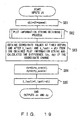
- the plot update process of the dynamic image composition apparatus shown in Fig. 18 is basically the same as that shown in Fig. 16. However, in step S63 shown in Fig. 16, the plot information generating unit 41 executes the plot information generating process shown in Fig. 19 using an update interval dt as an input and outputs plot coordinate difference (dx, dy).
- the plot information generating unit #i first multiplies the update interval dt by a parameter speedi, converts the update interval dt to an internal update interval dt1 (step S81) and obtains a plot information string corresponding to a plot information identifier IDk from the plot information string management unit 31 by executing the plot information string obtaining process shown in Fig. 14 (step S82).
- the plot information generating unit #i obtains coordinate values at times before and after t_lasti and t_lasti+dt1 from the plot information string and calculates the coordinate change difference (dx, dy) between t_lasti and t_lasti+dt1 by performing interpolation using these coordinate values (step S83).
- the plot information generating unit 41 can generate plot information using a plot information string instead of a plot information function.
- plot information generating units 23 and 41 are stored in the form of a list, these can be stored in an arbitrary form only if it is a structure where an element can be' added/deleted.
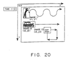
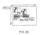
- Fig. 21 shows the dynamic image composition process by image management units 11 for managing these images.
- the dynamic image composition apparatus shown in Fig. 5 is used and both a plot information function 52 and a plot information string 32 are used.
- the image management unit 11 of image I1 stores image data 64, the most recent plot coordinates (x1,y1 ) and two plot information generating units #1 and #2
- the image management unit 11 of image I2 stores image data 64, the most recent plot coordinates (x2, y2) and one plot information generating unit 41
- the image management unit 11 of image I3 stores image data 64, the most recent plot coordinates (x3, y3) and one plot information generating unit 41.
- the plot information generating unit #1 of image I1 stores a plot information function identifier pf1
- the plot information generating unit #2 stores a plot information function identifier pf2.
- the plot information generating unit 41 of image I2 stores a plot information function identifier pf2, and the plot information generating unit 41 of image I3 stores a plot information string identifier ID1.
- Each plot information generating unit 41 calculates a position coordinate difference (dx, dy) using an update interval dt to be inputted and a stored last update time t_lasti and using a designated plot information function 52 or plot information string 32.
- the difference (dx, dy) is directly provided by each plot information function 52 and it is defined as follows.
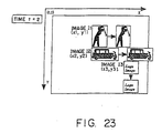
- each image continues to move according to a difference generated by each plot information generating unit 41 and added to the position coordinates, as shown in Fig. 23.
- Image I2 linearly moves rightward and image I3 moves along the locus of a square.
- the image management unit 11 adds the plot information generating unit #3. After this, differences generated by three plot information generating units #1, #2 and #3 are added and the position coordinates of image I1 is determined.
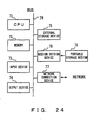
- the dynamic image composition apparatuses shown in Figs. 6, 11, 15 and 18 can be configured using an information processing device (computer) shown in Fig. 24.
- the information processing device shown in Fig. 24 comprises a CPU (central processing unit) 71, a memory 72, an input device 73, an output device 74, an external storage device 75, a medium driving device 76 and a network connection device 77, which are connected to one another by a bus 78.
- the memory 72 includes, for example, a ROM (read only memory), RAM (random access memory), etc., and it stores a program and data used for the process.
- the CPU 71 performs necessary processes by using the memory 72 and executing the program.
- the image management unit 11, plotting unit 12, image information function management unit 51, image information string management unit 31, image information generating units 23 and 41, etc. correspond to software components described by the program, and each component is stored in the specific program code segment of the memory 72.
- the list of pointers 61, event variable 62, update interval 63, image data 64, last plot coordinates 65, other plot coordinates 66, etc., are also stored in the memory 72.
- the input device 73 includes, for example, a keyboard, a pointing device, touch panel, etc., and it is used to input a user's instruction and information. Notification of an input operation to the input device 73 is also sometimes made to the plotting unit 12 as an event.
- the output device 74 includes, for example, the VRAM 13 and display 14 shown in Fig. 5, and it is used to output both inquiries to a user and composed dynamic images.
- the external storage device 75 includes, for example, a magnetic disk device, optical disk device, magneto-optical disk device, etc. This external storage device 75 can also store the program and data described above, and the program and data can be used by being loaded into the memory 72, if required.
- the external storage device 75 can also be used as a database for storing the image data 64, plot information function 52, plot information string 32, etc.
- the medium driving device 76 drives a portable storage medium 79 and accesses the recorded content.
- a portable storage medium an arbitrary computer readable storage medium, such as a memory card, floppy disk, CD-ROM (compact disk read only memory), optical disk, magneto-optical disk, etc., is used.
- the program and data described above can also be stored in this portable storage medium 79, and can also be used by being loaded into the memory 72, if required.
- the network connection device 77 communicates with external devices via an arbitrary network (line) , such as a LAN (local area network), etc., and transmits/receives data accompanying the communications.
- the connection network device can also receive the program and data from an external device and the program and data can be used by being loaded into the memory 72, if required.
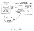
- Fig. 25 shows examples of computer readable storage media which can provide the information processing device shown in Fig. 24 with the program and data.
- the program and data stored in the portable storage medium 79 or an external database 80 can be loaded into the memory 72.
- the CPU 71 executes necessary processes by using the data and running the program.
- the image management unit 11 can also be implemented by hardware.
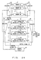
- Fig. 26 shows a case where a plurality of image management units 11 are configured by one hardware circuit.
- the image management unit shown in Fig. 26 comprises a plurality of memories 81 (#1-#M), selectors 82 and 83 for selecting a memory 81, a plurality of plot information generating circuits 84 (#1-#N), selectors 85 and 86 for selecting a plot information generating circuit 84 and a control circuit 87.
- the control circuit 87 switches between the selectors 82 and 83 by a control signal C1, switches between the selectors 85 and 86 by a control signal C2 and controls the plot information generating circuits 84 by a control signal C3.
- C1 switches between the selectors 82 and 83 by a control signal C1
- C2 switches between the selectors 85 and 86 by a control signal C2
- the memories #1-#M correspond to the image management units #1-#M, respectively, described above and they store plot information obtained at a previous time at time t.
- the plot information generating circuits #1-#N correspond to the plot information generating units #1-#N, respectively, and are described above and perform a calculation corresponding to one movement element and output the plot information. If the time t, an update interval dt and plot coordinates (x, y) at the previous time are used as input, outputted plot coordinates (x', y') are expressed as follows.
- x' fx(t, dt, x, y)
- y' fy(t, dt, x, y)
- dt corresponds to the difference between the previous time and the present time t
- fx(t, dt, x, y) and fy(t, dt, x, y) correspond to functions to generate an image movement.
- These functions can also output the history of past plot coordinates. For example, input coordinates (x_t1, y_t1) at time t1 can be stored, and a function to continue to output the coordinates (x_t1, y_t1) after time t1 can be defined.
- plot coordinate data are stored in a register of the plot information generating circuit 84 for each image, and appropriate data are outputted by switching the register by a control signal C3 from the control circuit 87.
- the selectors 85 and 86 are switched over, a plot information generating circuit #2 is selected and the plot information is inputted from the memory #1 to the plot information generating circuit #2. Then, plot coordinates are generated in the plot information generating circuit #2 in the same way as in the case of the plot information generating circuit #1, and the plot coordinates are stored in the memory #1. After such an operation is repeated for all plot information generating circuits 84 assigned to the image management unit #1, the output of the last plot information generating circuit 84 is outputted as the plot information at the present time of the image management unit #1. At this time, the plot information is simultaneously stored in the memory #1.
- the selectors 82 and 83 are switched over, the memory #1 is selected and the operation of the image management unit #2 is performed in the same way. After such an operation is repeated for M image management units, the plot update process at time t is completed.
- the circuit shown in Fig. 26 first selects a memory #1 using the selectors 82 and 83, and it selects a plot information generating circuit #1 using the selectors 85 and 86. In this way, the vertical vibration of sin(t) is added to the coordinates of the memory #1. Then, the circuit selects a plot information generating circuit #2 using the selectors 85 and 86. In this way, a rightward shift is added to the plot coordinates of a memory #1, and, as a result, plot coordinates in the case where the plot coordinates move rightward along the locus of a sine wave are outputted.
- the circuit selects a memory #2 using the selectors 82 and 83 and it selects the plot information generating circuit #1 using the selectors 85 and 86. In this way, the vertical vibration of sin(t) is added to the plot coordinates of the memory #2. Then, the circuit selects a plot information generating circuit #3 using the selectors 85 and 86. In this way, a leftward shift is added to the coordinates of the memory #2, and, as a result, plot coordinates in the case where the plot coordinates move leftward along the locus of a sine wave are outputted.
- the present invention is applicable to an arbitrary field, software or hardware, where a dynamic image moves as time elapses or according to an event.
- a dynamic image moves as time elapses or according to an event.
- the following are potential software applications.
- a vertical vibration with a rightward shift can be composed by separately generating a rightward shift and a vertical shift and by linking both to one image component when an image is reproduced. If this system is adopted, a movement can be dynamically added /deleted according to a user's instruction or time.
- the system can be configured in such a way that first a rightward shift is linked to an image component as a fundamental movement and a vertical vibration is added/deleted by a click event.
- a rightward shift and a rightward shift with a vertical vibration are separately configured and they are switched over by a click.
- the two movements are prepared without concern to the continuity, there is a possibility that the two movements may be discontinued when they are switched over.
- a multimedia title producer can handle each movement as a component. Since each kind of movement element is recorded in the completed multimedia title in a disassembled state, another producer can extract his/her favorite movement element from the multimedia title and can use the element as a movement component.
- a multimedia title including an image which moves along a specific path while vertically vibrating in a specific frequency includes two movement components, that is, a vertical vibration with a frequency and a shift along a path.
- the vertical vibration with a frequency can be implemented even in another multimedia title by extracting and using only the vertical vibration with the frequency.
- the conventional system since a movement is composed in advance when the multimedia title is produced, it is very difficult to extract only the vertical vibration with a frequency.
- a plot information function the vertical vibration of a sine wave and a leftward/rightward linear shift are used
- another arbitrary function can also be used.
- a plot information string is not limited to the locus of a square, and the locus of an arbitrary shape, such as a parabola, circle, ellipse, etc., can also be used for a plot information string.
- plot information generated by a plot information generating unit is not limited to the plot position of an image and it can also be the enlargement/reduction ratio, rotation angle, color, sequential relationship, etc., of an image component.
- a more complex dynamic image can be displayed by dynamically combining these pieces of information.
- a complex movement when a plurality of dynamic images are displayed on a screen, a complex movement can be easily generated by combining a plurality of movement elements. For example, a movement can be added/deleted in real time according to an event, a movement can be stopped or one movement element can be applied to a plurality of images.
Applications Claiming Priority (3)
| Application Number | Priority Date | Filing Date | Title |
|---|---|---|---|
| JP19560498A JP3348833B2 (ja) | 1998-07-10 | 1998-07-10 | 動画像合成装置 |
| JP19560498 | 1998-07-10 | ||
| EP99947068A EP1120748B1 (de) | 1998-07-10 | 1999-03-10 | Bewegungsbilderzeugungsgerät und-verfahren |
Related Parent Applications (2)
| Application Number | Title | Priority Date | Filing Date |
|---|---|---|---|
| EP99947068A Division EP1120748B1 (de) | 1998-07-10 | 1999-03-10 | Bewegungsbilderzeugungsgerät und-verfahren |
| EP99947068.5 Division | 1999-11-10 |
Publications (2)
| Publication Number | Publication Date |
|---|---|
| EP1343118A2 true EP1343118A2 (de) | 2003-09-10 |
| EP1343118A3 EP1343118A3 (de) | 2005-05-18 |
Family
ID=16343931
Family Applications (2)
| Application Number | Title | Priority Date | Filing Date |
|---|---|---|---|
| EP99947068A Expired - Lifetime EP1120748B1 (de) | 1998-07-10 | 1999-03-10 | Bewegungsbilderzeugungsgerät und-verfahren |
| EP03012223A Withdrawn EP1343118A3 (de) | 1998-07-10 | 1999-03-10 | Bewegungsbildererzeugungsgerät -program und -verfahren |
Family Applications Before (1)
| Application Number | Title | Priority Date | Filing Date |
|---|---|---|---|
| EP99947068A Expired - Lifetime EP1120748B1 (de) | 1998-07-10 | 1999-03-10 | Bewegungsbilderzeugungsgerät und-verfahren |
Country Status (5)
| Country | Link |
|---|---|
| US (3) | US7031018B1 (de) |
| EP (2) | EP1120748B1 (de) |
| JP (1) | JP3348833B2 (de) |
| DE (1) | DE69921843T2 (de) |
| WO (1) | WO2000003358A1 (de) |
Families Citing this family (4)
| Publication number | Priority date | Publication date | Assignee | Title |
|---|---|---|---|---|
| US8264489B2 (en) * | 2003-07-11 | 2012-09-11 | Intel Corporation | Interface remoting |
| US8249391B2 (en) * | 2007-08-24 | 2012-08-21 | Ancestry.com Operations, Inc. | User interface method for skew correction |
| US8370759B2 (en) | 2008-09-29 | 2013-02-05 | Ancestry.com Operations Inc | Visualizing, creating and editing blending modes methods and systems |
| KR101108480B1 (ko) * | 2010-02-24 | 2012-01-31 | (주)투비소프트 | 객체 지향적 컴포넌트 애니메이션 방법 및 이를 위한 기록매체 |
Citations (2)
| Publication number | Priority date | Publication date | Assignee | Title |
|---|---|---|---|---|
| JPS63143676A (ja) * | 1986-12-05 | 1988-06-15 | Fujitsu Ltd | アニメーション作成処理装置 |
| US5267334A (en) * | 1991-05-24 | 1993-11-30 | Apple Computer, Inc. | Encoding/decoding moving images with forward and backward keyframes for forward and reverse display |
Family Cites Families (19)
| Publication number | Priority date | Publication date | Assignee | Title |
|---|---|---|---|---|
| JP2949594B2 (ja) | 1990-03-28 | 1999-09-13 | 株式会社日立製作所 | 動画表示装置 |
| JP2861619B2 (ja) | 1991-07-12 | 1999-02-24 | 松下電器産業株式会社 | 情報提示装置及び提示情報作成装置 |
| EP0823818B1 (de) * | 1991-08-13 | 2002-01-09 | Canon Kabushiki Kaisha | Bildübertragungsvorrichtung |
| JPH07325934A (ja) * | 1992-07-10 | 1995-12-12 | Walt Disney Co:The | 仮想世界に向上したグラフィックスを提供する方法および装置 |
| JP3186242B2 (ja) | 1992-09-10 | 2001-07-11 | 富士通株式会社 | 図形編集装置 |
| JPH06167252A (ja) | 1992-11-30 | 1994-06-14 | Suzuki Motor Corp | 排気再循環装置 |
| JP2938739B2 (ja) * | 1993-02-26 | 1999-08-25 | 富士通株式会社 | 動画像処理装置 |
| US6262732B1 (en) * | 1993-10-25 | 2001-07-17 | Scansoft, Inc. | Method and apparatus for managing and navigating within stacks of document pages |
| JP3279041B2 (ja) | 1994-03-01 | 2002-04-30 | 松下電器産業株式会社 | アニメーション作成装置 |
| JPH08205066A (ja) * | 1995-01-26 | 1996-08-09 | Canon Inc | 画像形成装置及びシステム |
| JPH09167252A (ja) | 1995-12-19 | 1997-06-24 | Nippon Telegr & Teleph Corp <Ntt> | 動作入力による動画像生成処理方法 |
| US6147695A (en) * | 1996-03-22 | 2000-11-14 | Silicon Graphics, Inc. | System and method for combining multiple video streams |
| US6167562A (en) * | 1996-05-08 | 2000-12-26 | Kaneko Co., Ltd. | Apparatus for creating an animation program and method for creating the same |
| JPH1040411A (ja) | 1996-07-24 | 1998-02-13 | Nippon Telegr & Teleph Corp <Ntt> | 動画像生成方法および装置 |
| JPH1040357A (ja) | 1996-07-24 | 1998-02-13 | Nippon Telegr & Teleph Corp <Ntt> | 映像作成方法 |
| JPH1091795A (ja) * | 1996-09-12 | 1998-04-10 | Toshiba Corp | 移動物体検出装置及び移動物体検出方法 |
| JPH10198539A (ja) * | 1997-01-08 | 1998-07-31 | Fuji Xerox Co Ltd | 画像形成装置および画像形成方法 |
| US6014163A (en) * | 1997-06-09 | 2000-01-11 | Evans & Sutherland Computer Corporation | Multi-camera virtual set system employing still store frame buffers for each camera |
| JP2002133444A (ja) * | 2000-10-20 | 2002-05-10 | Matsushita Electric Ind Co Ltd | 映像情報作成装置 |
-
1998
- 1998-07-10 JP JP19560498A patent/JP3348833B2/ja not_active Expired - Fee Related
-
1999
- 1999-03-10 EP EP99947068A patent/EP1120748B1/de not_active Expired - Lifetime
- 1999-03-10 EP EP03012223A patent/EP1343118A3/de not_active Withdrawn
- 1999-03-10 DE DE69921843T patent/DE69921843T2/de not_active Expired - Fee Related
- 1999-03-10 WO PCT/JP1999/001153 patent/WO2000003358A1/ja active IP Right Grant
-
2000
- 2000-09-29 US US09/675,049 patent/US7031018B1/en not_active Expired - Fee Related
-
2006
- 2006-02-06 US US11/347,394 patent/US7542165B2/en not_active Expired - Fee Related
-
2007
- 2007-10-31 US US11/980,666 patent/US20080068623A1/en not_active Abandoned
Patent Citations (2)
| Publication number | Priority date | Publication date | Assignee | Title |
|---|---|---|---|---|
| JPS63143676A (ja) * | 1986-12-05 | 1988-06-15 | Fujitsu Ltd | アニメーション作成処理装置 |
| US5267334A (en) * | 1991-05-24 | 1993-11-30 | Apple Computer, Inc. | Encoding/decoding moving images with forward and backward keyframes for forward and reverse display |
Non-Patent Citations (3)
| Title |
|---|
| FOLEY J.D., ET AL: "Computer Graphics - Pinciples and Practice, p. 1065-1070" 1990, ADDISON-WESLEY , READING, MA, USA , XP002316957 * section 21.2.3 * * figure 21.5 * * |
| PATENT ABSTRACTS OF JAPAN vol. 012, no. 406 (P-777), 27 October 1988 (1988-10-27) & JP 63 143676 A (FUJITSU LTD), 15 June 1988 (1988-06-15) * |
| PENTLAND A ET AL: "Good vibrations: modal dynamics for graphics and animation" COMPUTER GRAPHICS USA, vol. 23, no. 3, 3 July 1989 (1989-07-03), pages 215-222, XP002316956 ISSN: 0097-8930 * |
Also Published As
| Publication number | Publication date |
|---|---|
| EP1343118A3 (de) | 2005-05-18 |
| DE69921843T2 (de) | 2005-06-16 |
| JP3348833B2 (ja) | 2002-11-20 |
| EP1120748B1 (de) | 2004-11-10 |
| US20060187508A1 (en) | 2006-08-24 |
| EP1120748A1 (de) | 2001-08-01 |
| US20080068623A1 (en) | 2008-03-20 |
| WO2000003358A1 (fr) | 2000-01-20 |
| US7542165B2 (en) | 2009-06-02 |
| EP1120748A4 (de) | 2001-08-08 |
| DE69921843D1 (de) | 2004-12-16 |
| US7031018B1 (en) | 2006-04-18 |
| JP2000030079A (ja) | 2000-01-28 |
Similar Documents
| Publication | Publication Date | Title |
|---|---|---|
| JP5244930B2 (ja) | ビデオズーミングシステム及び方法 | |
| JPH0644339A (ja) | 図形オブジェクト操作システム及び方法 | |
| JPWO2006046286A1 (ja) | データ配信システムおよびその方法 | |
| US8140999B2 (en) | Display process device and display process method | |
| US7542165B2 (en) | Dynamic image composition apparatus and method | |
| Gutierrez et al. | Semantics-based representation of virtual environments | |
| JP2007114822A (ja) | 自動レイアウト方法および装置 | |
| US6323878B1 (en) | System and method for providing zooming video capture | |
| CN115129224B (zh) | 移动控制的方法、装置、存储介质及电子设备 | |
| JP2003099795A (ja) | 動画像合成装置および方法 | |
| JP2842283B2 (ja) | 映像提示方法および装置 | |
| JPH10198823A (ja) | 映像生成装置 | |
| JPH05108776A (ja) | 画像表示方式 | |
| CN115640044B (zh) | 基于Unity的三维软件开发方法、装置、设备及介质 | |
| Vazirgiannis et al. | A Script Based Approach for Interactive Multimedia Applications. | |
| Armenakis | Mapping of spatio-temporal data in an active cartographic environment | |
| WO2002031776A1 (en) | Method and system for loading three dimensional visual objects into the video display area of a two dimensional graphical user interface | |
| JPH0736437A (ja) | 画像データ処理装置 | |
| KR20000029642A (ko) | 가상환경데이터브라우저 | |
| Gorgan et al. | Multimedia Synchronization Through Interactive Active Objects | |
| JP2536722B2 (ja) | 画像制御変更装置 | |
| Choi et al. | A Simple Event Model in Java3D-based VRML Browser | |
| Kim et al. | A simple event model in Java3D-based VRML browser | |
| JPH06161694A (ja) | 選択表示装置 | |
| JP2000311252A (ja) | 三次元画像生成システム、三次元画像生成方法及び記録媒体 |
Legal Events
| Date | Code | Title | Description |
|---|---|---|---|
| PUAI | Public reference made under article 153(3) epc to a published international application that has entered the european phase |
Free format text: ORIGINAL CODE: 0009012 |
|
| AC | Divisional application: reference to earlier application |
Ref document number: 1120748 Country of ref document: EP Kind code of ref document: P |
|
| AK | Designated contracting states |
Kind code of ref document: A2 Designated state(s): DE GB |
|
| PUAL | Search report despatched |
Free format text: ORIGINAL CODE: 0009013 |
|
| AK | Designated contracting states |
Kind code of ref document: A3 Designated state(s): DE GB |
|
| 17P | Request for examination filed |
Effective date: 20051110 |
|
| AKX | Designation fees paid |
Designated state(s): DE GB |
|
| 17Q | First examination report despatched |
Effective date: 20060724 |
|
| STAA | Information on the status of an ep patent application or granted ep patent |
Free format text: STATUS: THE APPLICATION IS DEEMED TO BE WITHDRAWN |
|
| 18D | Application deemed to be withdrawn |
Effective date: 20101001 |