EP1343045A1 - Exposure system for obtaining a sensitometric control patch with exposure gradient - Google Patents
Exposure system for obtaining a sensitometric control patch with exposure gradient Download PDFInfo
- Publication number
- EP1343045A1 EP1343045A1 EP03356026A EP03356026A EP1343045A1 EP 1343045 A1 EP1343045 A1 EP 1343045A1 EP 03356026 A EP03356026 A EP 03356026A EP 03356026 A EP03356026 A EP 03356026A EP 1343045 A1 EP1343045 A1 EP 1343045A1
- Authority
- EP
- European Patent Office
- Prior art keywords
- sensitometric
- photographic element
- exposure
- control patch
- photographic
- Prior art date
- Legal status (The legal status is an assumption and is not a legal conclusion. Google has not performed a legal analysis and makes no representation as to the accuracy of the status listed.)
- Withdrawn
Links
- 230000033001 locomotion Effects 0.000 claims abstract description 18
- 238000004519 manufacturing process Methods 0.000 claims abstract description 7
- 238000005259 measurement Methods 0.000 abstract description 9
- 230000003287 optical effect Effects 0.000 description 22
- 239000000839 emulsion Substances 0.000 description 13
- 238000000034 method Methods 0.000 description 10
- 238000005286 illumination Methods 0.000 description 8
- 239000000463 material Substances 0.000 description 3
- 238000012545 processing Methods 0.000 description 3
- 238000012546 transfer Methods 0.000 description 3
- 230000005540 biological transmission Effects 0.000 description 2
- 238000012822 chemical development Methods 0.000 description 2
- 239000003086 colorant Substances 0.000 description 2
- 238000011161 development Methods 0.000 description 2
- 238000012986 modification Methods 0.000 description 2
- 230000004048 modification Effects 0.000 description 2
- BQCADISMDOOEFD-UHFFFAOYSA-N Silver Chemical compound [Ag] BQCADISMDOOEFD-UHFFFAOYSA-N 0.000 description 1
- 238000005299 abrasion Methods 0.000 description 1
- 238000006243 chemical reaction Methods 0.000 description 1
- 238000012937 correction Methods 0.000 description 1
- 230000007547 defect Effects 0.000 description 1
- 230000006866 deterioration Effects 0.000 description 1
- 239000000428 dust Substances 0.000 description 1
- 238000013213 extrapolation Methods 0.000 description 1
- 230000002093 peripheral effect Effects 0.000 description 1
- 229910052709 silver Inorganic materials 0.000 description 1
- 239000004332 silver Substances 0.000 description 1
- 230000003595 spectral effect Effects 0.000 description 1
- 238000001228 spectrum Methods 0.000 description 1
Images


Classifications
-
- G—PHYSICS
- G03—PHOTOGRAPHY; CINEMATOGRAPHY; ANALOGOUS TECHNIQUES USING WAVES OTHER THAN OPTICAL WAVES; ELECTROGRAPHY; HOLOGRAPHY
- G03B—APPARATUS OR ARRANGEMENTS FOR TAKING PHOTOGRAPHS OR FOR PROJECTING OR VIEWING THEM; APPARATUS OR ARRANGEMENTS EMPLOYING ANALOGOUS TECHNIQUES USING WAVES OTHER THAN OPTICAL WAVES; ACCESSORIES THEREFOR
- G03B27/00—Photographic printing apparatus
- G03B27/72—Controlling or varying light intensity, spectral composition, or exposure time in photographic printing apparatus
-
- G—PHYSICS
- G03—PHOTOGRAPHY; CINEMATOGRAPHY; ANALOGOUS TECHNIQUES USING WAVES OTHER THAN OPTICAL WAVES; ELECTROGRAPHY; HOLOGRAPHY
- G03B—APPARATUS OR ARRANGEMENTS FOR TAKING PHOTOGRAPHS OR FOR PROJECTING OR VIEWING THEM; APPARATUS OR ARRANGEMENTS EMPLOYING ANALOGOUS TECHNIQUES USING WAVES OTHER THAN OPTICAL WAVES; ACCESSORIES THEREFOR
- G03B27/00—Photographic printing apparatus
- G03B27/32—Projection printing apparatus, e.g. enlarger, copying camera
- G03B27/52—Details
Definitions
- the present invention is in the photographic field, and is used to measure the sensitometric characteristics of a photographic element.
- the present invention relates more particularly to the production of a sensitometric control patch with exposure gradient, placed on a photographic element, and enabling the measurement of the sensitometric data of the photographic element.
- the sensitometric control patches of a photographic element comprise a set of sensitometric data that enable the photographic element to be calibrated against preset nominal values. From each of these control patches, the sensitometric curve specific to the photographic element is thus reproduced.
- the photographic element is for example a film strip or a strip of photographic paper.
- the response of a photographic film to light exposure varies according for example to its manufacturing process, the period and conditions of its storage, etc.
- the photographic processing chain can include "analog" operations of chemical development type, or digital operations.
- US Patent 6,284,445 describes a photographic element and a method enabling the area occupied by a plurality of sensitometric control patches to be optimized on the photographic element. The method also enables measurement of the sensitometric characteristics of the photographic element to be controlled, using a particular layout of the sensitometric control patches on said element.
- US Patent 3,718,074 describes a camera that includes a device enabling the sensitometric control patches incorporated in the film strip used in the camera to be exposed.
- the means described in this patent are bulky.
- US Patent 5,563,717 describes a particular method to produce a plurality of sensitometric control patches of constant width and different exposure levels, on a photographic element, by using a minimum surface area of the photographic element.
- the photographic element is for example a 35 mm photo film.
- US Patent 5,563,717 enables for example the dimensions of the means as described in US Patent 3,718,074 to be optimized.
- US Patent 5,667,944 describes a method enabling corrected photographic images to be obtained taking into account the actual optical density values of the negative film strip used to record the latent image originally recorded.
- the described method consists in forming at least two reference sensitometric control patches having different exposure levels on the photographic film strip.
- Patent Application DE 26,32,715 describes a correction method for color photographic films that uses three sensitometric control patches of different exposure levels on a film. The sensitometric control patches are placed between the perforations and outside the individual image locations on the film. The differences between the actual values of the sensitometric characteristics read of these sensitometric control patches and their nominal values enable color and image errors to be corrected. Document DE 26,32,715 also describes a camera including an exposure system for sensitometric control patches that enables, at each exposure of an individual image, the automatic exposure of a sensitometric control patch, so that individual image can be corrected later during copying or digital conversion.
- These constraints mean that the exposure, for example of a sensitometric control patch for each image recorded in a camera, at a rate of 150 images a second, requires perfectly controlling the energy and the exposure time of said control patch that will be used for reference.
- the accuracy of the corresponding sensitometric measurements will be all the more difficult to obtain, because of the variability generated by the camera's electronic and/or mechanical elements, and the repetition of the exposures.
- reading and saving the data for each of the sensitometric control patches requires a time incompatible with for example the running speed of the photographic elements.
- the present invention is based on the fact of obtaining the optical density curve of a photographic element as a function of the illumination, by the deconvolution of a unique sensitogram whose illumination function has been determined.
- the present invention relates more particularly to an exposure system of a photographic element comprising a light energy source placed along said photographic element, said light energy source being servo connected by an electrical link to a management module of the exposure parameters, said exposure system enabling a relative movement between the light energy source and the photographic element, and said exposure system being characterized in that it enables a light pulse to be produced whose respective digital values of the instant of emission, of the intensity, and the duration of the emission are automatically computed according to the nominal sensitometric characteristics of said photographic element and said values are automatically modified in time according to the instantaneous speed of relative movement of the light energy source in relation to the photographic element.
- the present invention further relates to the use of the exposure system presented below, to produce a reference sensitometric control patch on the photographic film strip placed in a recording or projection camera.
- the present invention has the advantage of only using a single sensitometric control patch per photographic element.
- This sensitometric control patch has the particularity of having non-uniform exposure levels.
- the present invention has the advantage, by meeting the above-mentioned speed and dimensions constraints, of only requiring a single reference sensitometric control patch per photographic element to be calibrated. The surface area and the time of the exposure sequence of the sensitometric control patch are thus optimized.
- the advantage provided by the invention is thus significant, given the above-mentioned constraints of time, measurement accuracy, and dimensions.
- Figure 1 represents diagrammatically an example of a photographic element comprising a unique sensitometric control patch according to the invention.
- Figure 2 represents a cross-section according to the line A-A of the Figure 1.
- Figure 3 represents a first preferred embodiment of a sensitometric control patch according to the invention.
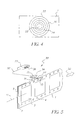
- Figure 4 represents a second embodiment of a sensitometric control patch according to the invention.
- Figure 5 represents diagrammatically and in perspective, the exposure system of the invention in relation to the photographic element.
- Figure 6 represents a sensitometric curve of a photographic element.
- sensitometric control patches placed on a silver-based photographic element generally use several sensitometric control patches per photographic element.
- the recording speed can vary for example from one to one hundred and fifty images a second, or even more, for certain special cameras. Consequently the exposure time (opening of the shutter) of an image location of a film strip running in a camera is often about several milliseconds.
- its sensitometric curve 40 is compared with the reference sensitometric curve 41.
- the sensitometric curve expresses the optical density values, between a minimum value Dmin and a maximum value Dmax, as a function of the exposure to light characterized by the illumination E.
- This illumination E expressed by its logarithm (Log E) is represented on a logarithmic scale ( Figure 6).
- the sensitometric control patches of the film strip are used to measure its sensitometric characteristics.
- the difference between the optical density values Do of the theoretical sensitometric curve 41 (reference film) and those of the sensitometric curve 40 of the film strip used for example in the camera are measured.
- several sensitometric control patches are necessary for one film strip. For example, for a 35 mm photo film, 21 different points, i.e.
- 21 sensitometric control patches are often used to measure the sensitometric exposures; said exposures are uniform for each point, and are given by the optical density values.
- the 21 values are saved and retrieved to form, by extrapolation, the sensitometric curve of the 35 mm film. Performing these multiple measurements raises problems, notably the overall dimensions of the exposure and/or measuring devices to be integrated into a recording camera for example.
- Figures 1 and 2 represent diagrammatically a photographic element 1 for implementing the invention.
- the photographic element 1 is for example a color photographic film strip used in a motion picture camera. But the photographic element 1 can also be a photographic paper type material support.
- the photographic element 1 comprises a material support 2 and a photosensitive emulsion layer 3 coated uniformly on the material support 2.
- the emulsion layer 3 generally comprises several emulsion sublayers that are successively coated on said support uniformly.
- the photographic element comprises a plurality of perforations 4 regularly spaced along the edges of said film strip 1. These perforations 4 are for moving the film strip 1 in the camera.
- the size, positioning and number of perforations per unit length are for example listed in standard ISO 491 on cinema.
- the film strip 1 comprises locations 5 enabling for example latent images to be received after exposure to light of said strip 1 in the camera.
- the present invention relates to an exposure system 38 for producing a sensitometric control patch 10, 20, used as reference, on a photographic element 1.
- the sensitometric control patch has non-uniform exposure and is unique for the entire photographic element 1. These latter characteristics are essential for the invention.
- the sensitometric control patch is unique for the emulsion 3 of the photographic element 1 and means that a single control patch is exposed for the entire photographic element 1, or that if several control patches are exposed along said photographic element 1, all these control patches are identical. In the latter case, for which the control patches are redundant, two identical control patches can be used, if one of them is for example contaminated by dust causing a defect on this control patch.
- the exposure system 38 of the invention enables, from a light energy source 31 with calibrated wavelengths, a light pulse to be transmitted as a light beam 33 onto the photosensitive layer 3.
- the wavelength is calibrated; i.e. the spectral curves of the various wavelengths are known for example in the red, green and blue color regions.
- the corresponding wavelengths are assessed, for example in nanometers. These wavelengths enable the colors of the various emulsion layers of the photographic element 1 to be exposed, for example the primary colors red, green, and blue.
- the light energy source 31 is channeled by a specific opening 34. This opening 34 can take various geometric shapes: circular, oblong, square, etc.
- the opening 34 has the shape of a narrow slot to let the light beam 33 be transmitted and focused onto the film strip 1.
- the opening 34 has a rectangular slot shape.
- the opening 34 is for example a few tenths of millimeters wide and a few millimeters long.
- the light beam 33 is preferably directed perpendicularly to the exposed sensitive surface 3.
- the light energy source 31 is integral with a box 30.
- the light energy source comprises at least one light emitting diode (LED).
- the narrow output slot 34 of the light channel is located at a preferred distance from 0.1 mm to 1 mm from the emulsion layer 3.
- the distance between the opening 34 and the film strip 1 depends on the dynamic stability level of the film strip 1 when this runs, in the direction 32, in front of the box 30. This distance prevents any abrasion or deterioration of said film when running. When the film 1 is stopped (not running), contact is permissible between said film and the opening 34.
- the box 30 can for example enclose one or more mirrors mutually arranged to channel the light beam 33 at the output 34 of said box 30.
- the box 30 is interfaced, via an electric link 37, with a management module of the exposure parameters 35.
- the exposure system 38 of the invention enables the transmission of a calibrated light pulse when the element 1 moves in relation to the light energy source 31. Movement of the film strip 1 is shown in Figure 5 by the arrow 32. Advantageously, this movement acts in one direction parallel to the principal axis 11 of the photographic element 1.
- the exposure system 38 of the invention enables the transmission to the emulsion layer 3 of a light pulse whose characteristics are managed from the instructions of an algorithm implemented by a microprocessor 36 located inside the module 35.
- the characteristics of the light pulse are produced from three exposure parameters: the respective digital values giving the emission instant, the intensity and the duration for which said pulse is emitted.
- the algorithm enables the automatic computation of these three exposure parameters (emission instant, intensity, and emission duration) according to the preset nominal values of the sensitometric characteristics of the optical density of the photographic element 1.
- the algorithm also enables the automatic adjustment or modification in real time when running, of the three exposure parameters, according to the instantaneous speed giving the relative movement between the light energy source 31 and the photographic element 1.
- the relative movement between the light energy source 31 and the photographic element 1 represents the running of the film in said camera.
- the management module 35 is itself servo connected to a measuring device (not shown in the figures) for the running speed.
- the algorithm implements digital value computations operated by a look up table (LUT).
- This LUT supplies a plurality of values for the exposure parameters according to the input data on the one hand for the nominal sensitometric characteristics of the photographic element 1, and on the other hand for the instantaneous speed of relative movement of the light energy source 31 in relation to the photographic element 1 (running of the film in the direction 32).
- the nominal sensitometric characteristics correspond for example to the optical density values of a given film: 200 ISO, 800 ISO, etc.
- the light pulse is transmitted to the emulsion layer 3 when the instantaneous speed of the relative movement of the light energy source 31 in relation to the photographic element 1 is zero; i.e. there is no relative movement between the light energy source 31 and the photographic element 1.
- a sensitometric control patch 20 is produced ( Figure 4).
- the exposure system 38 of the invention enables a latent image of a sensitometric control patch 10, 20, exposed or formed on a photographic element 1 to be obtained.
- the sensitometric control patch 10, 20 is placed on the photographic element, either at the location 7 of a latent image 5, or at another location 6, 8, 9, outside the latent image 5.
- the sensitometric control patch 10, 20 is unique for the photographic element 1, i.e. a single sensitometric control patch is enough to know all the sensitometric characteristics (optical densities, Dmin, Dmax) of said photographic element 1.
- the sensitometric control patch 10, 20 is exposed unevenly; i.e. the sensitometric control patch includes a gradient of exposures produced according to an exposure sequence implemented using the invention method.
- Figure 3 corresponds to the preferred embodiment of a sensitometric control patch 10 on the photographic element 1 when the instantaneous speed of the relative movement of the light energy source 31 in relation to the photographic element 1 is not zero, i.e. there is relative movement between the light energy source 31 and the photographic element 1.
- Production of the sensitometric control patch 10 is obtained by making for example the film strip 1 run in front of the light energy source 31.
- the algorithm used to implement the present invention enables the programming of an exposure gradient ranging for example from a highly exposed area 12 to a weakly exposed area 16, going through a set of areas 14 that correspond to intermediate exposures. These exposures are different from one another.
- the area 12 corresponds to the maximum optical density Dmax.
- the area 16 corresponds to the minimum optical density Dmin.
- the invention method programs for example two gradients of exposure areas each placed successively on about half the length of the sensitometric control patch 10 along its principal axis 18: a first gradient ranging for example from a highly exposed area (Dmax) to a weakly exposed area 14 (Dmin), then a second gradient ranging from said weakly exposed area 14 to a highly exposed area 16 (Dmax).
- the light energy also comprises a transversal gradient in a direction perpendicular to the axis 18.
- the sensitometric curve of the photographic element 1 is represented for example by the curve 40.
- This curve 40 is specific to the emulsion 3 of the photographic element 1 after the chemical development of said element.
- the "DlogE” sensitometric curve represents the optical density Do obtained as a function of the logarithmic function of the illumination light intensity E.
- the function f is a function characterizing the sensitometric curve for example of a photographic film strip. As the function f does not have a mathematical expression, it is determined by measurement.
- a photographic image or a sensitometric control patch recorded on a film strip 1 represents variations of optical density. These optical density variations are the result, after development of said film, of the convolution of the light generating the image or the sensitometric control patch, by the transfer function f specific to said film strip 1.
- Knowledge of the light (exposure), i.e. the light energy of the light beam 33, and measurement of the resulting optical density Do enable the determination of the transfer function f for the light energy in question.
- the characteristic f is determined in this way (point by point). This is a point by point deconvolution. This is for example used in the conventional case of a control patch strip with 21 ranges (including 21 sensitometric control patches).
- a continuous optical density gradient is obtained, and consequently continuous determination (or deconvolution) of the transfer function f.
- the algorithm of the invention method enables the computation of the various illumination levels E, which cover the exposure range enabling the sensitometric curve 40 of the film 1 to be formed, according to the instantaneous running speed of the film 1 and the physical characteristics of the system 38 (for example the electronics used, the size of slot 34).
- Exposure of the emulsion 3 comprises a lighting spatial gradient, and consequently involves, according to the previous equation, another spatial gradient of the optical density corresponding to said emulsion 3.
- the method and system of the invention enable, by exposing a single sensitometric control patch 10, 20, the lighting gradient to scan a sufficiently wide lighting range, to obtain all the possible optical densities of the photographic element 1.
- the algorithm used in the present invention enables the exposure parameters to be computed, and enables all the optical density values
- the sensitometric curve 40 gives the sensitometric response of the photographic element 1 to light energy, and this response can be compared with that of a curve 41 selected as reference.
- sensitometric control patches are obtained according to the shape of the opening 34. These shapes depend on the type of exposure system 38 used. A broad range of shapes can be generated by controlling the power (wave form) of the light beam 33 and according to the type of exposure system 38 used. In a preferred embodiment, the light beam 33 is uneven over its width at the output 34 of the exposure system 38; in this case the sensitometric control patch obtained is a flat hyperboloid type 15. If for example the light beam 33 is even over its width at the output 34 of the exposure system 38, the sensitometric control patch obtained is of the rectangular type 17.
- FIG. 4 shows another embodiment of a sensitometric control patch according to the invention.
- the light energy source 31 has a wave spectrum enabling the emission of a light pulse whose spatial intensity is not constant. This pulse is transmitted to the emulsion 3 of the photographic element 1 when the instantaneous speed of the relative movement of the light energy source 31 in relation to the photographic element 1 equals zero.
- the sensitometric control patch 20 produced is circular.
- the gradient of the exposure areas extends for example from a highly exposed central area 22 (Dmax) to a weakly exposed peripheral area 26 (Dmin), passing through differing intermediate exposure areas 24.
- the described invention can of course be used in a recording camera or projector, like for example a motion picture camera, to produce a reference sensitometric control patch, as defined in Claim 1, on the film strip used in the camera.
- the light energy source 31 is a light source independent from that used for example in the camera to expose the individual images in the locations 5.
Landscapes
- Physics & Mathematics (AREA)
- General Physics & Mathematics (AREA)
- Spectroscopy & Molecular Physics (AREA)
- Silver Salt Photography Or Processing Solution Therefor (AREA)
- Camera Data Copying Or Recording (AREA)
- Photometry And Measurement Of Optical Pulse Characteristics (AREA)
Abstract
The present invention is in the photographic field, and is used to measure the sensitometric characteristics of a photographic element (1), like for example a photographic film strip. The present invention relates more particularly to an exposure system (38) enabling the production of a sensitometric control patch with exposure gradient (10), (20), placed on a photographic element (1), and enabling the measurement of the sensitometric characteristics (40) of the photographic element (1).
The exposure system (38) comprises a light energy source (31) servo connected to a management module of the exposure parameters (35). The exposure system (38) enables the production on the exposed film strip (1) of the unique sensitometric control patch (10), (20), so that this sensitometric control patch includes a gradient of exposure areas (12), (14), (16), (22), (24), (26) enabling all the sensitometric characteristics (40) of said photographic film to be obtained. The sensitometric control patch (10), (20) is produced from the nominal sensitometric characteristics (41) of the film (1), and the instantaneous speed of relative movement of said film in front of the light energy source (31).
The present invention has its application in the photography field and in particular the motion picture field.
Description
- The present invention is in the photographic field, and is used to measure the sensitometric characteristics of a photographic element. The present invention relates more particularly to the production of a sensitometric control patch with exposure gradient, placed on a photographic element, and enabling the measurement of the sensitometric data of the photographic element.
- In the photographic field, it is important to control patch the entire chain of use and processing of a photographic film. In this field, the use of sensitometric control patches is known to those skilled in the art. The sensitometric control patches of a photographic element (film or photo paper) comprise a set of sensitometric data that enable the photographic element to be calibrated against preset nominal values. From each of these control patches, the sensitometric curve specific to the photographic element is thus reproduced. The photographic element is for example a film strip or a strip of photographic paper. The response of a photographic film to light exposure varies according for example to its manufacturing process, the period and conditions of its storage, etc. The photographic processing chain can include "analog" operations of chemical development type, or digital operations. Productivity constraints require fast adjustment of apparatus setting parameters, like for example a picture-taking camera or a digitizer (scanner), according to the sensitometric response specific to a film strip used for example in the recording camera. So it is particularly useful to know the sensitometric characteristics (optical densities) specific to said film strip, and to integrate them on-line in the apparatus used (camera, digitizer), to adapt the settings of the apparatus at the same time as the film is used (exposure, digitization). The targeted objective is to reproduce for the final customer images of an initial scene, having good reproduction quality without loosing time. Therefore, and in relation to the medium or photographic element used, one means known to those skilled in the art is to reconstitute the sensitometric curve specific to this photographic element, using sensitometric control patches specific to said photographic element.
- US Patent 6,284,445 describes a photographic element and a method enabling the area occupied by a plurality of sensitometric control patches to be optimized on the photographic element. The method also enables measurement of the sensitometric characteristics of the photographic element to be controlled, using a particular layout of the sensitometric control patches on said element.
- US Patent 3,718,074 describes a camera that includes a device enabling the sensitometric control patches incorporated in the film strip used in the camera to be exposed. The means described in this patent are bulky.
- US Patent 5,563,717 describes a particular method to produce a plurality of sensitometric control patches of constant width and different exposure levels, on a photographic element, by using a minimum surface area of the photographic element. The photographic element is for example a 35 mm photo film. US Patent 5,563,717 enables for example the dimensions of the means as described in US Patent 3,718,074 to be optimized.
- US Patent 5,667,944 describes a method enabling corrected photographic images to be obtained taking into account the actual optical density values of the negative film strip used to record the latent image originally recorded. The described method consists in forming at least two reference sensitometric control patches having different exposure levels on the photographic film strip.
-
Patent Application DE 26,32,715 describes a correction method for color photographic films that uses three sensitometric control patches of different exposure levels on a film. The sensitometric control patches are placed between the perforations and outside the individual image locations on the film. The differences between the actual values of the sensitometric characteristics read of these sensitometric control patches and their nominal values enable color and image errors to be corrected. Document DE 26,32,715 also describes a camera including an exposure system for sensitometric control patches that enables, at each exposure of an individual image, the automatic exposure of a sensitometric control patch, so that individual image can be corrected later during copying or digital conversion. - Contrary to the image quality requirements, the technical constraints of speed (several tens of images a second) and dimensions (reduced dimensions and weight of equipment), entail using as few sensitometric control patches as possible. These constraints mean that the exposure, for example of a sensitometric control patch for each image recorded in a camera, at a rate of 150 images a second, requires perfectly controlling the energy and the exposure time of said control patch that will be used for reference. The accuracy of the corresponding sensitometric measurements will be all the more difficult to obtain, because of the variability generated by the camera's electronic and/or mechanical elements, and the repetition of the exposures. Furthermore, even using advanced recording means, reading and saving the data for each of the sensitometric control patches requires a time incompatible with for example the running speed of the photographic elements.
- The present invention is based on the fact of obtaining the optical density curve of a photographic element as a function of the illumination, by the deconvolution of a unique sensitogram whose illumination function has been determined.
- The present invention relates more particularly to an exposure system of a photographic element comprising a light energy source placed along said photographic element, said light energy source being servo connected by an electrical link to a management module of the exposure parameters, said exposure system enabling a relative movement between the light energy source and the photographic element, and said exposure system being characterized in that it enables a light pulse to be produced whose respective digital values of the instant of emission, of the intensity, and the duration of the emission are automatically computed according to the nominal sensitometric characteristics of said photographic element and said values are automatically modified in time according to the instantaneous speed of relative movement of the light energy source in relation to the photographic element.
- The present invention further relates to the use of the exposure system presented below, to produce a reference sensitometric control patch on the photographic film strip placed in a recording or projection camera.
- Compared with the means described in the prior art, the present invention has the advantage of only using a single sensitometric control patch per photographic element. This sensitometric control patch has the particularity of having non-uniform exposure levels. Compared with the prior art, the present invention has the advantage, by meeting the above-mentioned speed and dimensions constraints, of only requiring a single reference sensitometric control patch per photographic element to be calibrated. The surface area and the time of the exposure sequence of the sensitometric control patch are thus optimized. The advantage provided by the invention is thus significant, given the above-mentioned constraints of time, measurement accuracy, and dimensions.
- Other characteristics will appear on reading the following description, with reference to the drawings of the various figures.
- Figure 1 represents diagrammatically an example of a photographic element comprising a unique sensitometric control patch according to the invention.
- Figure 2 represents a cross-section according to the line A-A of the Figure 1.
- Figure 3 represents a first preferred embodiment of a sensitometric control patch according to the invention.
- Figure 4 represents a second embodiment of a sensitometric control patch according to the invention.
- Figure 5 represents diagrammatically and in perspective, the exposure system of the invention in relation to the photographic element.
- Figure 6 represents a sensitometric curve of a photographic element.
- The following description is a detailed description of the main embodiments of the invention, with reference to the drawings in which the same numerical references identify the same elements in each of the different figures.
- The means described in the prior art and comprising sensitometric control patches placed on a silver-based photographic element generally use several sensitometric control patches per photographic element. Inside a recording camera, the recording speed can vary for example from one to one hundred and fifty images a second, or even more, for certain special cameras. Consequently the exposure time (opening of the shutter) of an image location of a film strip running in a camera is often about several milliseconds. To calibrate the film strip used against a reference film, according to Figure 6, its
sensitometric curve 40 is compared with the referencesensitometric curve 41. The sensitometric curve expresses the optical density values, between a minimum value Dmin and a maximum value Dmax, as a function of the exposure to light characterized by the illumination E. This illumination E, expressed by its logarithm (Log E), is represented on a logarithmic scale (Figure 6). The sensitometric control patches of the film strip are used to measure its sensitometric characteristics. To calibrate the film strip used, for the same exposure sequence, the difference between the optical density values Do of the theoretical sensitometric curve 41 (reference film) and those of thesensitometric curve 40 of the film strip used for example in the camera are measured. Frequently, given the quality of the final images to be obtained (after processing), several sensitometric control patches are necessary for one film strip. For example, for a 35 mm photo film, 21 different points, i.e. 21 sensitometric control patches, are often used to measure the sensitometric exposures; said exposures are uniform for each point, and are given by the optical density values. The 21 values are saved and retrieved to form, by extrapolation, the sensitometric curve of the 35 mm film. Performing these multiple measurements raises problems, notably the overall dimensions of the exposure and/or measuring devices to be integrated into a recording camera for example. - Figures 1 and 2 represent diagrammatically a
photographic element 1 for implementing the invention. Thephotographic element 1 is for example a color photographic film strip used in a motion picture camera. But thephotographic element 1 can also be a photographic paper type material support. Thephotographic element 1 comprises amaterial support 2 and aphotosensitive emulsion layer 3 coated uniformly on thematerial support 2. Theemulsion layer 3 generally comprises several emulsion sublayers that are successively coated on said support uniformly. In the case of a film strip, the photographic element comprises a plurality ofperforations 4 regularly spaced along the edges of saidfilm strip 1. Theseperforations 4 are for moving thefilm strip 1 in the camera. The size, positioning and number of perforations per unit length are for example listed in standard ISO 491 on cinema. Thefilm strip 1 compriseslocations 5 enabling for example latent images to be received after exposure to light of saidstrip 1 in the camera. - The present invention relates to an
exposure system 38 for producing asensitometric control patch photographic element 1. The sensitometric control patch has non-uniform exposure and is unique for the entirephotographic element 1. These latter characteristics are essential for the invention. The sensitometric control patch is unique for theemulsion 3 of thephotographic element 1 and means that a single control patch is exposed for the entirephotographic element 1, or that if several control patches are exposed along saidphotographic element 1, all these control patches are identical. In the latter case, for which the control patches are redundant, two identical control patches can be used, if one of them is for example contaminated by dust causing a defect on this control patch. - According to Figure 5, the
exposure system 38 of the invention enables, from alight energy source 31 with calibrated wavelengths, a light pulse to be transmitted as alight beam 33 onto thephotosensitive layer 3. The wavelength is calibrated; i.e. the spectral curves of the various wavelengths are known for example in the red, green and blue color regions. The corresponding wavelengths are assessed, for example in nanometers. These wavelengths enable the colors of the various emulsion layers of thephotographic element 1 to be exposed, for example the primary colors red, green, and blue. Thelight energy source 31 is channeled by aspecific opening 34. Thisopening 34 can take various geometric shapes: circular, oblong, square, etc. Advantageously, theopening 34 has the shape of a narrow slot to let thelight beam 33 be transmitted and focused onto thefilm strip 1. In a particular embodiment, theopening 34 has a rectangular slot shape. Theopening 34 is for example a few tenths of millimeters wide and a few millimeters long. Thelight beam 33 is preferably directed perpendicularly to the exposedsensitive surface 3. Thelight energy source 31 is integral with abox 30. Advantageously, the light energy source comprises at least one light emitting diode (LED). Thenarrow output slot 34 of the light channel is located at a preferred distance from 0.1 mm to 1 mm from theemulsion layer 3. The distance between theopening 34 and thefilm strip 1 depends on the dynamic stability level of thefilm strip 1 when this runs, in thedirection 32, in front of thebox 30. This distance prevents any abrasion or deterioration of said film when running. When thefilm 1 is stopped (not running), contact is permissible between said film and theopening 34. Thebox 30 can for example enclose one or more mirrors mutually arranged to channel thelight beam 33 at theoutput 34 of saidbox 30. Thebox 30 is interfaced, via anelectric link 37, with a management module of theexposure parameters 35. - In a preferred embodiment, the
exposure system 38 of the invention enables the transmission of a calibrated light pulse when theelement 1 moves in relation to thelight energy source 31. Movement of thefilm strip 1 is shown in Figure 5 by thearrow 32. Advantageously, this movement acts in one direction parallel to theprincipal axis 11 of thephotographic element 1. Theexposure system 38 of the invention enables the transmission to theemulsion layer 3 of a light pulse whose characteristics are managed from the instructions of an algorithm implemented by amicroprocessor 36 located inside themodule 35. The characteristics of the light pulse are produced from three exposure parameters: the respective digital values giving the emission instant, the intensity and the duration for which said pulse is emitted. The algorithm enables the automatic computation of these three exposure parameters (emission instant, intensity, and emission duration) according to the preset nominal values of the sensitometric characteristics of the optical density of thephotographic element 1. The algorithm also enables the automatic adjustment or modification in real time when running, of the three exposure parameters, according to the instantaneous speed giving the relative movement between thelight energy source 31 and thephotographic element 1. In a camera, the relative movement between thelight energy source 31 and thephotographic element 1 represents the running of the film in said camera. Themanagement module 35 is itself servo connected to a measuring device (not shown in the figures) for the running speed. The algorithm implements digital value computations operated by a look up table (LUT). This LUT supplies a plurality of values for the exposure parameters according to the input data on the one hand for the nominal sensitometric characteristics of thephotographic element 1, and on the other hand for the instantaneous speed of relative movement of thelight energy source 31 in relation to the photographic element 1 (running of the film in the direction 32). The nominal sensitometric characteristics correspond for example to the optical density values of a given film: 200 ISO, 800 ISO, etc. In a particular embodiment of the implementation of the invention, the light pulse is transmitted to theemulsion layer 3 when the instantaneous speed of the relative movement of thelight energy source 31 in relation to thephotographic element 1 is zero; i.e. there is no relative movement between thelight energy source 31 and thephotographic element 1. In this particular embodiment, asensitometric control patch 20 is produced (Figure 4). - The
exposure system 38 of the invention enables a latent image of asensitometric control patch photographic element 1 to be obtained. Thesensitometric control patch latent image 5, or at anotherlocation latent image 5. Thesensitometric control patch photographic element 1, i.e. a single sensitometric control patch is enough to know all the sensitometric characteristics (optical densities, Dmin, Dmax) of saidphotographic element 1. Thesensitometric control patch - Figure 3 corresponds to the preferred embodiment of a
sensitometric control patch 10 on thephotographic element 1 when the instantaneous speed of the relative movement of thelight energy source 31 in relation to thephotographic element 1 is not zero, i.e. there is relative movement between thelight energy source 31 and thephotographic element 1. Production of thesensitometric control patch 10 is obtained by making for example thefilm strip 1 run in front of thelight energy source 31. The algorithm used to implement the present invention enables the programming of an exposure gradient ranging for example from a highly exposedarea 12 to a weakly exposedarea 16, going through a set ofareas 14 that correspond to intermediate exposures. These exposures are different from one another. Advantageously, thearea 12 corresponds to the maximum optical density Dmax. Advantageously, thearea 16 corresponds to the minimum optical density Dmin. In an alternative of this embodiment, the invention method programs for example two gradients of exposure areas each placed successively on about half the length of thesensitometric control patch 10 along its principal axis 18: a first gradient ranging for example from a highly exposed area (Dmax) to a weakly exposed area 14 (Dmin), then a second gradient ranging from said weakly exposedarea 14 to a highly exposed area 16 (Dmax). The light energy also comprises a transversal gradient in a direction perpendicular to the axis 18. There is a cumulation and use of the gradients in the axis 18 and perpendicularly to said axis 18. According to Figure 6, the sensitometric curve of thephotographic element 1 is represented for example by thecurve 40. Thiscurve 40 is specific to theemulsion 3 of thephotographic element 1 after the chemical development of said element. The "DlogE" sensitometric curve represents the optical density Do obtained as a function of the logarithmic function of the illumination light intensity E. The function "f' characterizing the optical density Do is written as the simple generic equation:
base 10,
where Do represents the optical density, and E represents the illumination. The function f is a function characterizing the sensitometric curve for example of a photographic film strip. As the function f does not have a mathematical expression, it is determined by measurement. The illumination E of any point with coordinates (x, y) located on thephotographic emulsion 3 and the measurement of the resulting optical density Do at the same point with coordinates (x, y), enable the determination, point by point and continuously, of the function f, and consequently thesensitometric curve 40 of thefilm 1. The relationship between Do, E and f is given by the equation:
sensitometric curve 40 of saidphotographic element 1 after development. - A photographic image or a sensitometric control patch recorded on a
film strip 1 represents variations of optical density. These optical density variations are the result, after development of said film, of the convolution of the light generating the image or the sensitometric control patch, by the transfer function f specific to saidfilm strip 1. Knowledge of the light (exposure), i.e. the light energy of thelight beam 33, and measurement of the resulting optical density Do enable the determination of the transfer function f for the light energy in question. By proceeding point by point, the characteristic f is determined in this way (point by point). This is a point by point deconvolution. This is for example used in the conventional case of a control patch strip with 21 ranges (including 21 sensitometric control patches). Similarly, when using a continuous exposure gradient as in the present invention, a continuous optical density gradient is obtained, and consequently continuous determination (or deconvolution) of the transfer function f. The algorithm of the invention method enables the computation of the various illumination levels E, which cover the exposure range enabling thesensitometric curve 40 of thefilm 1 to be formed, according to the instantaneous running speed of thefilm 1 and the physical characteristics of the system 38 (for example the electronics used, the size of slot 34). - Exposure of the
emulsion 3 comprises a lighting spatial gradient, and consequently involves, according to the previous equation, another spatial gradient of the optical density corresponding to saidemulsion 3. The method and system of the invention enable, by exposing a singlesensitometric control patch photographic element 1. The algorithm used in the present invention enables the exposure parameters to be computed, and enables all the optical density values Do representative of thesensitometric curve 40 of thephotographic element 1 to be measured from the exposure of a singlesensitometric control patch sensitometric curve 40 gives the sensitometric response of thephotographic element 1 to light energy, and this response can be compared with that of acurve 41 selected as reference. - Different shapes of sensitometric control patches are obtained according to the shape of the
opening 34. These shapes depend on the type ofexposure system 38 used. A broad range of shapes can be generated by controlling the power (wave form) of thelight beam 33 and according to the type ofexposure system 38 used. In a preferred embodiment, thelight beam 33 is uneven over its width at theoutput 34 of theexposure system 38; in this case the sensitometric control patch obtained is aflat hyperboloid type 15. If for example thelight beam 33 is even over its width at theoutput 34 of theexposure system 38, the sensitometric control patch obtained is of therectangular type 17. - Figure 4 shows another embodiment of a sensitometric control patch according to the invention. The
light energy source 31 has a wave spectrum enabling the emission of a light pulse whose spatial intensity is not constant. This pulse is transmitted to theemulsion 3 of thephotographic element 1 when the instantaneous speed of the relative movement of thelight energy source 31 in relation to thephotographic element 1 equals zero. Thesensitometric control patch 20 produced is circular. The gradient of the exposure areas extends for example from a highly exposed central area 22 (Dmax) to a weakly exposed peripheral area 26 (Dmin), passing through differingintermediate exposure areas 24. - The described invention can of course be used in a recording camera or projector, like for example a motion picture camera, to produce a reference sensitometric control patch, as defined in
Claim 1, on the film strip used in the camera. In a preferred embodiment of the implementation of the invention, thelight energy source 31 is a light source independent from that used for example in the camera to expose the individual images in thelocations 5. - While the invention has been described with reference to the preferred embodiments, it is clear that this patent application covers all modifications or variants that can be made and which correspond with the purpose of the invention. Accordingly, such embodiments are for illustration only and do not restrict the claimed protection.
Claims (4)
- An exposure system (38) of a photographic element (1), characterized in that it enables the production on the photographic element (1) of a unique means to calibrate the photographic element (1), said unique means comprising a latent image of a sensitometric control patch (10), (20), and said sensitometric control patch (10), (20) comprising at least one gradient of exposure areas (12), (14), (16), (22), (24), (26).
- The exposure system (38) of a photographic element (1) according to Claim 1, comprising a light energy source (31) placed along said photographic element, said light energy source being servo connected by an electrical link (37) to a management module of the exposure parameters (35), said exposure system (38) enabling a relative movement between the light energy source (31) and the photographic element (1), and said exposure system being characterized in that it enables the production of a light pulse following a light beam (33), the respective digital values of the emission instant, the intensity, and the duration of the emission of said light pulse being automatically computed according to the nominal sensitometric characteristics (Do) of said photographic element (1) and said values being automatically modified in time according to the instantaneous speed of relative movement of the light energy source (31) in relation to the photographic element (1), so as to produce a unique sensitometric control patch (10), (20), said sensitometric control patch comprising at least one gradient of exposure areas (12), (14), (16), (22), (24), (26).
- The exposure system (38) according to either one of the Claims 1 or 2, wherein the light energy source (31) comprises at least one light emitting diode (LED) with calibrated wave length.
- Use of the exposure system (38) according to any one of the Claims 1 to 3, to produce a reference sensitometric control patch (10), (20) on a photographic film strip (1) placed in a recording or projection camera.
Applications Claiming Priority (2)
| Application Number | Priority Date | Filing Date | Title |
|---|---|---|---|
| FR0202860 | 2002-03-07 | ||
| FR0202860A FR2837006B1 (en) | 2002-03-07 | 2002-03-07 | EXPOSURE SYSTEM FOR OBTAINING A GRADIENT SENSITOMETRIC INDICATOR |
Publications (1)
| Publication Number | Publication Date |
|---|---|
| EP1343045A1 true EP1343045A1 (en) | 2003-09-10 |
Family
ID=27741449
Family Applications (1)
| Application Number | Title | Priority Date | Filing Date |
|---|---|---|---|
| EP03356026A Withdrawn EP1343045A1 (en) | 2002-03-07 | 2003-02-17 | Exposure system for obtaining a sensitometric control patch with exposure gradient |
Country Status (4)
| Country | Link |
|---|---|
| US (1) | US6829435B2 (en) |
| EP (1) | EP1343045A1 (en) |
| JP (1) | JP2003270712A (en) |
| FR (1) | FR2837006B1 (en) |
Citations (4)
| Publication number | Priority date | Publication date | Assignee | Title |
|---|---|---|---|---|
| US3718074A (en) * | 1971-05-13 | 1973-02-27 | R Davis | Color data acquisition camera |
| US4335956A (en) * | 1979-03-23 | 1982-06-22 | Agfa-Gevaert Aktiengesellschaft | Method and apparatus for adjusting associated photographic copying and developing machines |
| US4757334A (en) * | 1986-12-09 | 1988-07-12 | Ivan Volent | System for density correction of medical imaging film hard copy |
| FR2678745A1 (en) * | 1991-07-05 | 1993-01-08 | Gen Electric Cgr | Method and devices for printing a sensitogram on each photographic negative, and negative thus obtained |
Family Cites Families (6)
| Publication number | Priority date | Publication date | Assignee | Title |
|---|---|---|---|---|
| DE2632715A1 (en) | 1976-07-21 | 1978-01-26 | Geb Kiesewetter Britt Lippmann | Automatic correction for colour cine film - using reference strips of three primary colours exposed during filming for subsequent processing control |
| US5563717A (en) | 1995-02-03 | 1996-10-08 | Eastman Kodak Company | Method and means for calibration of photographic media using pre-exposed miniature images |
| US5649260A (en) * | 1995-06-26 | 1997-07-15 | Eastman Kodak Company | Automated photofinishing apparatus |
| US5667944A (en) | 1995-10-25 | 1997-09-16 | Eastman Kodak Company | Digital process sensitivity correction |
| US5917987A (en) * | 1996-08-16 | 1999-06-29 | Neyman; Yuri | System for controlling the transfer of an image on a first medium to a second medium |
| US6284445B1 (en) | 2000-08-09 | 2001-09-04 | Eastman Kodak Company | Reference calibration patch arrangement to minimize exposure and measurement artifacts and maximize robustness to defects |
-
2002
- 2002-03-07 FR FR0202860A patent/FR2837006B1/en not_active Expired - Fee Related
-
2003
- 2003-02-17 EP EP03356026A patent/EP1343045A1/en not_active Withdrawn
- 2003-03-04 JP JP2003057600A patent/JP2003270712A/en active Pending
- 2003-03-06 US US10/382,780 patent/US6829435B2/en not_active Expired - Fee Related
Patent Citations (4)
| Publication number | Priority date | Publication date | Assignee | Title |
|---|---|---|---|---|
| US3718074A (en) * | 1971-05-13 | 1973-02-27 | R Davis | Color data acquisition camera |
| US4335956A (en) * | 1979-03-23 | 1982-06-22 | Agfa-Gevaert Aktiengesellschaft | Method and apparatus for adjusting associated photographic copying and developing machines |
| US4757334A (en) * | 1986-12-09 | 1988-07-12 | Ivan Volent | System for density correction of medical imaging film hard copy |
| FR2678745A1 (en) * | 1991-07-05 | 1993-01-08 | Gen Electric Cgr | Method and devices for printing a sensitogram on each photographic negative, and negative thus obtained |
Also Published As
| Publication number | Publication date |
|---|---|
| US6829435B2 (en) | 2004-12-07 |
| JP2003270712A (en) | 2003-09-25 |
| US20030170016A1 (en) | 2003-09-11 |
| FR2837006A1 (en) | 2003-09-12 |
| FR2837006B1 (en) | 2004-11-05 |
Similar Documents
| Publication | Publication Date | Title |
|---|---|---|
| EP1232418B1 (en) | Method and system for using calibration patches in electronic film processing | |
| US5447811A (en) | Color image reproduction of scenes with preferential tone mapping | |
| JPH0232613B2 (en) | ||
| JPH0640194B2 (en) | How to set and manage photo printing conditions | |
| US6816678B2 (en) | Method for obtaining a sensitometric control patch with exposure gradient and photographic element comprising such a control patch | |
| GB2123968A (en) | Color printer | |
| US6829435B2 (en) | Exposure system for obtaining a sensitometric control patch with exposure gradient | |
| EP0381668B1 (en) | System for calibration and control of a photographic color printer | |
| KR20090004871A (en) | Method and device for previewing digital video content | |
| JPH09312731A (en) | Illuminance setting method | |
| JP2837757B2 (en) | Printing method for photo printing equipment | |
| JP2502134B2 (en) | Photographic exposure amount determination device | |
| US5760882A (en) | Contact printer and method of making a filter for a contact printer | |
| US5856864A (en) | Photographic printer and method of making a filter for a photographic printer | |
| US6810209B2 (en) | Method to establish sensitometry curve for a photographic medium | |
| US7254324B2 (en) | Systems and methods for film processing quality control | |
| JP2502131B2 (en) | Method for determining photoprint exposure | |
| JP3248600B2 (en) | Imaging device | |
| JPS63257744A (en) | Method for setting and managing copying condition | |
| JP3719775B2 (en) | Image input device | |
| JPH09326924A (en) | Shading correction method | |
| JP2010074759A (en) | Method of removing density variation in 3-dimensional lookup table for image signal conversion | |
| JPS6269127A (en) | Color information measurement device | |
| JPH0293449A (en) | Film kind managing device for photographic printer | |
| WO1995026099A1 (en) | Color image reproduction of scenes with preferential tone mapping |
Legal Events
| Date | Code | Title | Description |
|---|---|---|---|
| PUAI | Public reference made under article 153(3) epc to a published international application that has entered the european phase |
Free format text: ORIGINAL CODE: 0009012 |
|
| AK | Designated contracting states |
Kind code of ref document: A1 Designated state(s): AT BE BG CH CY CZ DE DK EE ES FI FR GB GR HU IE IT LI LU MC NL PT SE SI SK TR |
|
| AX | Request for extension of the european patent |
Extension state: AL LT LV MK RO |
|
| AKX | Designation fees paid | ||
| REG | Reference to a national code |
Ref country code: DE Ref legal event code: 8566 |
|
| STAA | Information on the status of an ep patent application or granted ep patent |
Free format text: STATUS: THE APPLICATION IS DEEMED TO BE WITHDRAWN |
|
| 18D | Application deemed to be withdrawn |
Effective date: 20040311 |