EP1342653A2 - Air bag apparatus for a scooter type motorcycle - Google Patents
Air bag apparatus for a scooter type motorcycle Download PDFInfo
- Publication number
- EP1342653A2 EP1342653A2 EP03005009A EP03005009A EP1342653A2 EP 1342653 A2 EP1342653 A2 EP 1342653A2 EP 03005009 A EP03005009 A EP 03005009A EP 03005009 A EP03005009 A EP 03005009A EP 1342653 A2 EP1342653 A2 EP 1342653A2
- Authority
- EP
- European Patent Office
- Prior art keywords
- air bag
- vehicle body
- seat
- operator
- restraining
- Prior art date
- Legal status (The legal status is an assumption and is not a legal conclusion. Google has not performed a legal analysis and makes no representation as to the accuracy of the status listed.)
- Granted
Links
Images


Classifications
-
- B—PERFORMING OPERATIONS; TRANSPORTING
- B60—VEHICLES IN GENERAL
- B60R—VEHICLES, VEHICLE FITTINGS, OR VEHICLE PARTS, NOT OTHERWISE PROVIDED FOR
- B60R21/00—Arrangements or fittings on vehicles for protecting or preventing injuries to occupants or pedestrians in case of accidents or other traffic risks
- B60R21/02—Occupant safety arrangements or fittings, e.g. crash pads
- B60R21/16—Inflatable occupant restraints or confinements designed to inflate upon impact or impending impact, e.g. air bags
- B60R21/23—Inflatable members
- B60R21/231—Inflatable members characterised by their shape, construction or spatial configuration
- B60R21/2334—Expansion control features
- B60R21/2338—Tethers
-
- B—PERFORMING OPERATIONS; TRANSPORTING
- B60—VEHICLES IN GENERAL
- B60R—VEHICLES, VEHICLE FITTINGS, OR VEHICLE PARTS, NOT OTHERWISE PROVIDED FOR
- B60R21/00—Arrangements or fittings on vehicles for protecting or preventing injuries to occupants or pedestrians in case of accidents or other traffic risks
- B60R21/02—Occupant safety arrangements or fittings, e.g. crash pads
- B60R21/16—Inflatable occupant restraints or confinements designed to inflate upon impact or impending impact, e.g. air bags
-
- B—PERFORMING OPERATIONS; TRANSPORTING
- B62—LAND VEHICLES FOR TRAVELLING OTHERWISE THAN ON RAILS
- B62J—CYCLE SADDLES OR SEATS; AUXILIARY DEVICES OR ACCESSORIES SPECIALLY ADAPTED TO CYCLES AND NOT OTHERWISE PROVIDED FOR, e.g. ARTICLE CARRIERS OR CYCLE PROTECTORS
- B62J27/00—Safety equipment
- B62J27/20—Airbags specially adapted for motorcycles or the like
-
- B—PERFORMING OPERATIONS; TRANSPORTING
- B60—VEHICLES IN GENERAL
- B60R—VEHICLES, VEHICLE FITTINGS, OR VEHICLE PARTS, NOT OTHERWISE PROVIDED FOR
- B60R21/00—Arrangements or fittings on vehicles for protecting or preventing injuries to occupants or pedestrians in case of accidents or other traffic risks
- B60R2021/0002—Type of accident
- B60R2021/0004—Frontal collision
-
- B—PERFORMING OPERATIONS; TRANSPORTING
- B60—VEHICLES IN GENERAL
- B60R—VEHICLES, VEHICLE FITTINGS, OR VEHICLE PARTS, NOT OTHERWISE PROVIDED FOR
- B60R21/00—Arrangements or fittings on vehicles for protecting or preventing injuries to occupants or pedestrians in case of accidents or other traffic risks
- B60R2021/0065—Type of vehicles
- B60R2021/0088—Cycles, e.g. motorcycles
-
- B—PERFORMING OPERATIONS; TRANSPORTING
- B60—VEHICLES IN GENERAL
- B60R—VEHICLES, VEHICLE FITTINGS, OR VEHICLE PARTS, NOT OTHERWISE PROVIDED FOR
- B60R21/00—Arrangements or fittings on vehicles for protecting or preventing injuries to occupants or pedestrians in case of accidents or other traffic risks
- B60R21/02—Occupant safety arrangements or fittings, e.g. crash pads
- B60R21/16—Inflatable occupant restraints or confinements designed to inflate upon impact or impending impact, e.g. air bags
- B60R21/23—Inflatable members
- B60R21/231—Inflatable members characterised by their shape, construction or spatial configuration
- B60R21/2334—Expansion control features
- B60R21/2338—Tethers
- B60R2021/23386—External tether means
-
- B—PERFORMING OPERATIONS; TRANSPORTING
- B60—VEHICLES IN GENERAL
- B60R—VEHICLES, VEHICLE FITTINGS, OR VEHICLE PARTS, NOT OTHERWISE PROVIDED FOR
- B60R21/00—Arrangements or fittings on vehicles for protecting or preventing injuries to occupants or pedestrians in case of accidents or other traffic risks
- B60R21/02—Occupant safety arrangements or fittings, e.g. crash pads
- B60R21/06—Safety nets, transparent sheets, curtains, or the like, e.g. between occupants and glass
- B60R21/08—Safety nets, transparent sheets, curtains, or the like, e.g. between occupants and glass automatically movable from an inoperative to an operative position, e.g. in a collision
-
- B—PERFORMING OPERATIONS; TRANSPORTING
- B60—VEHICLES IN GENERAL
- B60R—VEHICLES, VEHICLE FITTINGS, OR VEHICLE PARTS, NOT OTHERWISE PROVIDED FOR
- B60R21/00—Arrangements or fittings on vehicles for protecting or preventing injuries to occupants or pedestrians in case of accidents or other traffic risks
- B60R21/02—Occupant safety arrangements or fittings, e.g. crash pads
- B60R21/16—Inflatable occupant restraints or confinements designed to inflate upon impact or impending impact, e.g. air bags
- B60R21/20—Arrangements for storing inflatable members in their non-use or deflated condition; Arrangement or mounting of air bag modules or components
- B60R21/215—Arrangements for storing inflatable members in their non-use or deflated condition; Arrangement or mounting of air bag modules or components characterised by the covers for the inflatable member
- B60R21/2165—Arrangements for storing inflatable members in their non-use or deflated condition; Arrangement or mounting of air bag modules or components characterised by the covers for the inflatable member characterised by a tear line for defining a deployment opening
-
- B—PERFORMING OPERATIONS; TRANSPORTING
- B60—VEHICLES IN GENERAL
- B60R—VEHICLES, VEHICLE FITTINGS, OR VEHICLE PARTS, NOT OTHERWISE PROVIDED FOR
- B60R21/00—Arrangements or fittings on vehicles for protecting or preventing injuries to occupants or pedestrians in case of accidents or other traffic risks
- B60R21/02—Occupant safety arrangements or fittings, e.g. crash pads
- B60R21/16—Inflatable occupant restraints or confinements designed to inflate upon impact or impending impact, e.g. air bags
- B60R21/20—Arrangements for storing inflatable members in their non-use or deflated condition; Arrangement or mounting of air bag modules or components
- B60R21/217—Inflation fluid source retainers, e.g. reaction canisters; Connection of bags, covers, diffusers or inflation fluid sources therewith or together
- B60R21/2171—Inflation fluid source retainers, e.g. reaction canisters; Connection of bags, covers, diffusers or inflation fluid sources therewith or together specially adapted for elongated cylindrical or bottle-like inflators with a symmetry axis perpendicular to the main direction of bag deployment, e.g. extruded reaction canisters
-
- B—PERFORMING OPERATIONS; TRANSPORTING
- B62—LAND VEHICLES FOR TRAVELLING OTHERWISE THAN ON RAILS
- B62K—CYCLES; CYCLE FRAMES; CYCLE STEERING DEVICES; RIDER-OPERATED TERMINAL CONTROLS SPECIALLY ADAPTED FOR CYCLES; CYCLE AXLE SUSPENSIONS; CYCLE SIDE-CARS, FORECARS, OR THE LIKE
- B62K2202/00—Motorised scooters
Definitions
- the present invention relates to an air bag apparatus for a scooter type motorcycle, having an air bag that is capable of restraining an operator on a seat from a front direction, in response to expansion of the air bag.
- the present invention was made considering the above situation, and the objective of the present invention is to provide an air bag apparatus for a scooter type motorcycle, which is capable of securely restraining the operator on the seat, without a need for enlarging the expansion volume of the air bag, even when the yaw behavior and/or rolling behavior of the vehicle body are/is large.
- the invention as defined by claim 1 features an air bag apparatus for a scooter type motorcycle, comprising an air bag that is capable of retraining an operator on a seat from a front direction, in response to expansion of the air bag, wherein, the air bag and a vehicle body in the rear of the seat are linked via restraining belts or retraining nets, being a pair at right and left, which are stored in the vehicle body when the air bag is in a state of folded, and which become in a state of tension on both exterior sides at right and left of an operator on the seat, when the air bag expands.
- the restraining belts or the restraining nets are arranged in a state of tension on the both right and left exterior sides of the operator on the seat, at the time of air bag expansion in response to an action of shock against the vehicle. Therefore, it is possible to restrain the operator from the both right and left sides, with the restraining belts or the restraining nets, even when the yaw behavior and/or the rolling behavior of the vehicle body are/is large, and acoordingly, it is possible to securely restrain the operator from a front direction, even with the air bag having a small expansion volume.
- restraining belts or restraining nets are arranged in a state of tension at right and left exterior sides of an operator on the seat, when the air bag expands. Therefore, it is possible to restrain the operator from both right and left sides with restraining belts or the restraining nets, even if a yaw behavior and/or a rolling behavior of the vehicle body are/is large, whereby the operator can be securely restrained even with the air bag having a small expansion volume.
- a vehicle body cover constituting the vehicle body together with a vehicle body frame having a head pipe on a front end thereof, the head pipe supporting a front fork in orientation-manipulative manner, comprises a front cover, which covers a circumference of the head pipe, and an air bag housing for storing the air bag is installed at a forward position of the seat and in the rear of the front cover.
- a scooter type motorcycle having a concave shape between the seat and the head pipe, formed by denting downwardly the vehicle body, does not need a large modification of the vehicle body shape, and it is possible by the air bag, to securely restrain the operator on the seat from a front direction.
- the vehicle body cover comprises, in addition to the front cover, leg shields, being a pair at right and left for covering forward portions of the operator's legs, the leg shields being joined with both right and left sides of the front cover, respectively, footrest sections, being a pair at right and left connecting respectively to the leg shields for supporting feet of the operator, and a rear cover jointed with the footrest sections, for covering both right and left sides of a rear part of the vehicle body frame, wherein, the restraining belts or the restraining nets, an end of which is fixedly linked with the air bag and another end of which is linked with the rear cover, are stored in storage grooves, being a pair at right and left, which are provided over along the front cover, the leg shields, the footrest sections and the rear cover, in such a manner as allowing the restraining belts or the restraining nets to be pulled out, in response to a tension thereof, with expansion
- the scooter type motorcycle having footrest sections formed between the seat and the front cover, to store the restraining belt or the restraining nets, so as not to be obstacles at the time of getting on/off and driving, as well as maintaining a natural external view, when the air bag is in a state of non-expanded.
- the scooter type motorcycle having footrest sections formed between the seat and the front cover to store the restraining belts or retraining nets, so as not to be obstacles at the time of getting on/off and driving, as well as maintaining a natural external view, when the air bag is in a state of non-expanded.
- Fig. 1 to Fig. 4 show a first embodiment of the present invention.
- Fig. 1 is a side view of a scooter type motorcycle
- Fig. 2 is an enlarged cross sectional view of Fig. 1, taken along line 2-2
- Fig. 3 is a side view of the scooter type motorcycle, at the time of air bag expansion
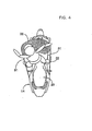
- Fig. 4 is a plan view of Fig. 3
- a front fork 7 is supported in orientation-manipulative manner, and a front wheel WF is axially supported at the lower end of the front fork 7.
- An orientation-manipulating handle 8 is coupled with the upper portion of the front fork 7.
- a power unit 9 containing an engine and a transmission is mounted, and a rear wheel WR is axially supported in the rear of a swing arm 10, which is supported by the rear part of the power unit 9, in such a manner that wobbling up and down is possible. Further, a power from the power unit 9 is transmitted to the rear wheel WR via an endless type chain 11.
- a rear cushion unit 13 is installed between a seat rail 12 and the swing arm 10, which are provided in the rear of the vehicle body frame 5.
- the vehicle body frame 5 is covered with a vehicle body cover 15, made of synthetic resin, which constitutes the vehicle body 14 together with the vehicle body frame 5, and the vehicle body cover 15 covers a circumference of the head pipe 6, and further comprises a front cover 16 for covering the front wheel WF from above, leg shields 17, being a pair at right and left for covering a forward portion of the operator's legs, the leg shields being joined with both right and left sides of the front cover 16, respectively, footrest sections 18, being a pair at right and left, connecting to the leg shields 17, respectively, so as to support the feet of the operator, a floor tunnel section 19 that is raised upwardly between the footrest sections 18, skirt sections 20 that are hanging downwardly from outer edges of the both footrest sections 18, respectively, and a rear cover 21 which is joined with the footrest sections 18 and the floor tunnel section 19, covering the both right and left sides of the rear part of the vehicle body frame 5.
- a vehicle body cover 15 made of synthetic resin, which constitutes the vehicle body 14 together with the vehicle body frame 5, and the vehicle body cover 15 covers a
- FIG. 2 it is shown that at a position in front of the operator sitting on the front seat 22, for example, in the rear of the front cover 16, an air bag module 24 of the air bag apparatus is installed.
- the air bag module 24 comprises an air bag housing 25, an air bag 26 stored in the air bag housing 25, and an inflator 27 to generate gas for expanding the air bag 26.
- the air bag housing 25 comprises a storage tube unit 28, which is formed in a shape of tube having a tangible bottom, made of synthetic resin, in such a manner that it is capable of storing the air bag 26 in a folded manner, and a cover unit 29 for closing an upper end opening of the storage tube unit 28, and the storage tube unit 28 is installed in the rear of the front cover 16, either integrally or as a separate member.
- a fragile portion 29a is provided, except one point in the peripheral direction, and the fragile portion 29a is formed in such a manner that it is capable of bursting easily.
- the air bag 26 is formed in a shape of bag, having an opening potion 26a on the undersurface thereof, and it is stored in the air bag housing 25, in a folded manner. Further, the inflator 27 is supported by a cap 30 that is mounted fixedly to the opening portion 26a on the undersurface of the air bag 26, and the cap 30 is fixed on a block end of the storage tube unit 28.
- a shock detecting sensor (not shown), such as acceleration sensor, is installed on the vehicle body frame 5, and the inflator 27 is activated in response to a detection of shock by the shock detecting sensor, the shock being not smaller than a predetermined value, so as to provide high pressure gas into the air bag 26.
- both restraining belts 31, 31 are fixedly attached to both right and left sides of the rear cover 21 of the vehicle body 14, in the rear of the front seat 22.
- a length of these restraining belts 31, 31 becomes short so that those belts can be stored in the vehicle body 14 when the air bag 26 is folded within the air bag housing 25.
- the restraining belts are set to be in a state of tension on the both right and left exterior sides of the operator on the front seat 22.
- storage grooves 33 which are pair at right and left allowing the restraining belts 31, 31 to be stored therein, are provided over along the front cover 16, the leg shield 17, the footrests 18 and the rear cover 21. These storage grooves 33 are covered with a cover (not shown), which is capable of bursting in accordance with the tension of the restraining belts 31, 31 accompanied with expansion of the air bag 26.
- the restraining belts 31 are stored in the storing grooves 33, so as to be pulled out in response to the tension of the restraining belts 31, with expansion of the air bag 26.
- the shock detecting sensor detects a shock of not smaller than a predetermined value, due to a collision and the like
- the inflator 27 is activated and provides high pressure gas into the air bag 26.
- the air bag 26 allows the fragile part 29a of the air bag housing 25 to burst, and expands upwards instantaneously, along with opening the cover unit 29. Accordingly, the operator sitting on the front seat 22 is restrained from the front direction with thus expanded air bag 26.
- the air bag 26 and the rear cover 21 of the vehicle body 14 in the rear of the front seat 22 are linked via restraining belts 31, 31, being a pair at right and left, which are stored in the vehicle body cover 15 of the vehicle body 14, when the air bag 26 is in a state of folded, and which become in a state of tension, at right and left exterior sides of the operator on the seat 22, when the air bag expands.
- the restraining belts 31, 31 are arranged in a state of tension at right and left exterior sides of the operator on the front seat 22, whereby the operator can be restrained from the both sides right and left with the restraining belts 31, 31, even if a yaw behavior and/or a rolling behavior of the vehicle body 14 are/is large. Therefore, it is possible to securely restrain the operator from the front direction even with the air bag 26 having a small expansion volume.
- the air bag housing 25 for storing the air bag 26 is installed at a forward position of the front seat 22 and in the rear of the front cover 16, a scooter type motorcycle having a concave shape between the front seat 22 and the head pipe 6, formed by denting downwardly the vehicle body 14, does not need a large modification of the vehicle body shape, and it is possible by the air bag 26, to securely restrain the operator on the front seat 22 from a front direction.
- the restraining belts 31, an end of which is fixedly linked with the air bag 26 and another end of which is linked with the rear cover 21 are stored in storage grooves 33, being a pair at right and left, which are provided over along the front cover 16, the leg shields 17, the footrest sections 18 and the rear cover 21, in such a manner as allowing the restraining belts 31 to be pulled out, in response to a tension thereof, with expansion of the air bag 26.
- the scooter type motorcycle having footrest sections 18 formed between the front seat 22 and the front cover 16 to store the restraining belts 31, so as not to be obstacles at the time of getting on/off and driving, as well as maintaining a natural external view, when the air bag 26 is in a state of non-expanded.
- Fig. 5 shows the second embodiment of the present invention, and to the parts corresponding to first embodiment, explanations of the identical reference numbers are applied.
- the air bag 26 for restraining the operator on the front seat 22 from the front direction in response to expansion of the air bag, and the rear cover 21 of the vehicle body 14 in the rear of the front seat 22 are linked via restraining nets 35, being pair at right and left, which are stored in the vehicle body cover 15 of the vehicle body, when the air bag 26 is in a state of folded, and which become in a state of tension in the both right and left exterior sides of the operator on the front seat 22, when the air bag 26 expands.
- These restraining nets 35 are made of nylon, for example.
- An objective of the present invention is to provide an air bag apparatus for a compact vehicle, having an air bag that is capable of restraining an operator on a seat from a front direction, in response to expansion of the air bag, wherein it is possible to securely restrain the operator on the seat without a need for enlarging the expansion volume of the air bag, even if a yaw behavior and/or a rolling behavior of the vehicle body are/is large.
- the air bag 26 and the vehicle 14 in the rear of the seat 22 are linked via restraining belts 31, being a pair at right and left, which are stored in the vehicle body 14, when the air bag 26 is in a state of folded, and which become in a state of tension, at right and left exterior sides of the operator on the seat 22, when the air bag 26 expands.
Abstract
Description
- The present invention relates to an air bag apparatus for a scooter type motorcycle, having an air bag that is capable of restraining an operator on a seat from a front direction, in response to expansion of the air bag.
- Conventionally, a type of such air bag apparatus is already known, for example, by the following patent document 1, gazette of Japanese patent application laid-open No. Hei 9-328053 etc.
- However, with the conventional apparatus, there is a possibility that the operator cannot be restrained sufficiently, even when the air bag expands in front of the operator on the seat, in the case where yaw behavior and/or rolling behavior of the vehicle body are/is large. In order to achieve a secured restraint, it is necessary to enlarge the expansion volume of the air bag, and accordingly, other components, such as inflator, tend to become oversized.
- The present invention was made considering the above situation, and the objective of the present invention is to provide an air bag apparatus for a scooter type motorcycle, which is capable of securely restraining the operator on the seat, without a need for enlarging the expansion volume of the air bag, even when the yaw behavior and/or rolling behavior of the vehicle body are/is large.
- In order to achieve the above objective, the invention as defined by claim 1 features an air bag apparatus for a scooter type motorcycle, comprising an air bag that is capable of retraining an operator on a seat from a front direction, in response to expansion of the air bag, wherein, the air bag and a vehicle body in the rear of the seat are linked via restraining belts or retraining nets, being a pair at right and left, which are stored in the vehicle body when the air bag is in a state of folded, and which become in a state of tension on both exterior sides at right and left of an operator on the seat, when the air bag expands.
- With the configuration of the invention as defined by claim 1, the restraining belts or the restraining nets are arranged in a state of tension on the both right and left exterior sides of the operator on the seat, at the time of air bag expansion in response to an action of shock against the vehicle. Therefore, it is possible to restrain the operator from the both right and left sides, with the restraining belts or the restraining nets, even when the yaw behavior and/or the rolling behavior of the vehicle body are/is large, and acoordingly, it is possible to securely restrain the operator from a front direction, even with the air bag having a small expansion volume.
- According to the invention as defined in claim 1, restraining belts or restraining nets are arranged in a state of tension at right and left exterior sides of an operator on the seat, when the air bag expands. Therefore, it is possible to restrain the operator from both right and left sides with restraining belts or the restraining nets, even if a yaw behavior and/or a rolling behavior of the vehicle body are/is large, whereby the operator can be securely restrained even with the air bag having a small expansion volume.
- The invention defined by
claim 2 features that, in addition to the configuration of the invention as defined by claim 1, a vehicle body cover constituting the vehicle body together with a vehicle body frame having a head pipe on a front end thereof, the head pipe supporting a front fork in orientation-manipulative manner, comprises a front cover, which covers a circumference of the head pipe, and an air bag housing for storing the air bag is installed at a forward position of the seat and in the rear of the front cover. With this configuration, on a scooter type motorcycle having a concave shape between the seat and the head pipe, formed by denting downwardly the vehicle body, it is possible by the air bag, to securely restrain the operator on the seat from a front direction, without a large modification of the vehicle body shape. - Furthermore, according to the invention as defined in
claim 2, a scooter type motorcycle having a concave shape between the seat and the head pipe, formed by denting downwardly the vehicle body, does not need a large modification of the vehicle body shape, and it is possible by the air bag, to securely restrain the operator on the seat from a front direction. - Furthermore, the invention defined by claim 3 features, in addition to the configuration of the invention as defined by
claim 2, the vehicle body cover comprises, in addition to the front cover, leg shields, being a pair at right and left for covering forward portions of the operator's legs, the leg shields being joined with both right and left sides of the front cover, respectively, footrest sections, being a pair at right and left connecting respectively to the leg shields for supporting feet of the operator, and a rear cover jointed with the footrest sections, for covering both right and left sides of a rear part of the vehicle body frame, wherein, the restraining belts or the restraining nets, an end of which is fixedly linked with the air bag and another end of which is linked with the rear cover, are stored in storage grooves, being a pair at right and left, which are provided over along the front cover, the leg shields, the footrest sections and the rear cover, in such a manner as allowing the restraining belts or the restraining nets to be pulled out, in response to a tension thereof, with expansion of the air bag. With this configuration, it is possible for the scooter type motorcycle having footrest sections formed between the seat and the front cover, to store the restraining belt or the restraining nets, so as not to be obstacles at the time of getting on/off and driving, as well as maintaining a natural external view, when the air bag is in a state of non-expanded. - Furthermore, according to the invention as defined in claim 3, it is possible for the scooter type motorcycle having footrest sections formed between the seat and the front cover to store the restraining belts or retraining nets, so as not to be obstacles at the time of getting on/off and driving, as well as maintaining a natural external view, when the air bag is in a state of non-expanded.
- Hereinafter, modes for carrying out the present invention will be explained, based on the embodiments of the present invention as shown in the attached drawings, in which:
- Fig. 1 is a side view of a scooter type motorcycle of the first embodiment of the present invention.
- Fig. 2 is an enlarged cross sectional view of Fig. 1, taken along line 2-2.
- Fig. 3 is a side view of the scooter type motorcycle, at the time of air bag expansion.
- Fig. 4 is a plan view of Fig. 3.
- Fig. 5 is a side view of a scooter type motorcycle of the second embodiment of the present invention.
- Fig. 1 to Fig. 4 show a first embodiment of the present invention. Fig. 1 is a side view of a scooter type motorcycle, Fig. 2 is an enlarged cross sectional view of Fig. 1, taken along line 2-2, Fig. 3 is a side view of the scooter type motorcycle, at the time of air bag expansion, and Fig. 4 is a plan view of Fig. 3
- Firstly, in Fig. 1, at a
head pipe 6 provided at a front end of avehicle body frame 5 of the scooter type motorcycle. afront fork 7 is supported in orientation-manipulative manner, and a front wheel WF is axially supported at the lower end of thefront fork 7. An orientation-manipulatinghandle 8 is coupled with the upper portion of thefront fork 7. - At a midway between the front and rear of the
vehicle body frame 5, apower unit 9 containing an engine and a transmission is mounted, and a rear wheel WR is axially supported in the rear of aswing arm 10, which is supported by the rear part of thepower unit 9, in such a manner that wobbling up and down is possible. Further, a power from thepower unit 9 is transmitted to the rear wheel WR via anendless type chain 11. - A
rear cushion unit 13 is installed between aseat rail 12 and theswing arm 10, which are provided in the rear of thevehicle body frame 5. - The
vehicle body frame 5 is covered with avehicle body cover 15, made of synthetic resin, which constitutes thevehicle body 14 together with thevehicle body frame 5, and thevehicle body cover 15 covers a circumference of thehead pipe 6, and further comprises afront cover 16 for covering the front wheel WF from above,leg shields 17, being a pair at right and left for covering a forward portion of the operator's legs, the leg shields being joined with both right and left sides of thefront cover 16, respectively,footrest sections 18, being a pair at right and left, connecting to theleg shields 17, respectively, so as to support the feet of the operator, afloor tunnel section 19 that is raised upwardly between thefootrest sections 18,skirt sections 20 that are hanging downwardly from outer edges of the bothfootrest sections 18, respectively, and arear cover 21 which is joined with thefootrest sections 18 and thefloor tunnel section 19, covering the both right and left sides of the rear part of thevehicle body frame 5. - On the
rear cover 21, afront seat 22 on which an operator sits, and arear seat 23, on which a fellow passenger sits, the rear seat being arranged in the rear of thefront seat 22. - Also referring to Fig. 2, it is shown that at a position in front of the operator sitting on the
front seat 22, for example, in the rear of thefront cover 16, anair bag module 24 of the air bag apparatus is installed. - The
air bag module 24 comprises anair bag housing 25, anair bag 26 stored in theair bag housing 25, and aninflator 27 to generate gas for expanding theair bag 26. - The
air bag housing 25 comprises astorage tube unit 28, which is formed in a shape of tube having a tangible bottom, made of synthetic resin, in such a manner that it is capable of storing theair bag 26 in a folded manner, and acover unit 29 for closing an upper end opening of thestorage tube unit 28, and thestorage tube unit 28 is installed in the rear of thefront cover 16, either integrally or as a separate member. - On the periphery of the
cover unit 29, afragile portion 29a is provided, except one point in the peripheral direction, and thefragile portion 29a is formed in such a manner that it is capable of bursting easily. - The
air bag 26 is formed in a shape of bag, having an opening potion 26a on the undersurface thereof, and it is stored in theair bag housing 25, in a folded manner. Further, theinflator 27 is supported by acap 30 that is mounted fixedly to the opening portion 26a on the undersurface of theair bag 26, and thecap 30 is fixed on a block end of thestorage tube unit 28. - A shock detecting sensor (not shown), such as acceleration sensor, is installed on the
vehicle body frame 5, and theinflator 27 is activated in response to a detection of shock by the shock detecting sensor, the shock being not smaller than a predetermined value, so as to provide high pressure gas into theair bag 26. - At a position corresponding to the
fragile portion 29a and between thestorage tube unit 28 and thecover unit 29 of theair bag housing 25, throughholes restraining belts holes air bag housing 25, so that those restraining belts are fixedly joined with the both sides of theair bag 26, respectively. - The other ends of both
restraining belts rear cover 21 of thevehicle body 14, in the rear of thefront seat 22. A length of theserestraining belts vehicle body 14 when theair bag 26 is folded within theair bag housing 25. On the other hand, when theair bag 26 expands, the restraining belts are set to be in a state of tension on the both right and left exterior sides of the operator on thefront seat 22. - On the
vehicle body cover 15 of thevehicle body 14, storage grooves 33, which are pair at right and left allowing therestraining belts front cover 16, theleg shield 17, thefootrests 18 and therear cover 21. These storage grooves 33 are covered with a cover (not shown), which is capable of bursting in accordance with the tension of therestraining belts air bag 26. In other words, therestraining belts 31 are stored in the storing grooves 33, so as to be pulled out in response to the tension of therestraining belts 31, with expansion of theair bag 26. - Next, an operation of the first embodiment will be explained. When the shock detecting sensor detects a shock of not smaller than a predetermined value, due to a collision and the like, the
inflator 27 is activated and provides high pressure gas into theair bag 26. Then, as shown in Fig. 3 and Fig. 4, theair bag 26 allows thefragile part 29a of the air bag housing 25 to burst, and expands upwards instantaneously, along with opening thecover unit 29. Accordingly, the operator sitting on thefront seat 22 is restrained from the front direction with thus expandedair bag 26. - In the meantime, the
air bag 26 and therear cover 21 of thevehicle body 14 in the rear of thefront seat 22 are linked viarestraining belts vehicle body cover 15 of thevehicle body 14, when theair bag 26 is in a state of folded, and which become in a state of tension, at right and left exterior sides of the operator on theseat 22, when the air bag expands. - Accordingly, when the
air bag 26 expands, therestraining belts front seat 22, whereby the operator can be restrained from the both sides right and left with therestraining belts vehicle body 14 are/is large. Therefore, it is possible to securely restrain the operator from the front direction even with theair bag 26 having a small expansion volume. - In addition, since the air bag housing 25 for storing the
air bag 26 is installed at a forward position of thefront seat 22 and in the rear of thefront cover 16, a scooter type motorcycle having a concave shape between thefront seat 22 and thehead pipe 6, formed by denting downwardly thevehicle body 14, does not need a large modification of the vehicle body shape, and it is possible by theair bag 26, to securely restrain the operator on thefront seat 22 from a front direction.
Moreover, therestraining belts 31, an end of which is fixedly linked with theair bag 26 and another end of which is linked with therear cover 21 are stored in storage grooves 33, being a pair at right and left, which are provided over along thefront cover 16, theleg shields 17, thefootrest sections 18 and therear cover 21, in such a manner as allowing therestraining belts 31 to be pulled out, in response to a tension thereof, with expansion of theair bag 26. With this configuration, it is possible for the scooter type motorcycle havingfootrest sections 18 formed between thefront seat 22 and thefront cover 16 to store therestraining belts 31, so as not to be obstacles at the time of getting on/off and driving, as well as maintaining a natural external view, when theair bag 26 is in a state of non-expanded. - Fig. 5 shows the second embodiment of the present invention, and to the parts corresponding to first embodiment, explanations of the identical reference numbers are applied.
- The
air bag 26 for restraining the operator on thefront seat 22 from the front direction in response to expansion of the air bag, and therear cover 21 of thevehicle body 14 in the rear of thefront seat 22 are linked viarestraining nets 35, being pair at right and left, which are stored in thevehicle body cover 15 of the vehicle body, when theair bag 26 is in a state of folded, and which become in a state of tension in the both right and left exterior sides of the operator on thefront seat 22, when theair bag 26 expands. These restrainingnets 35 are made of nylon, for example. - Similar effects as achieved by the first embodiment can be attained by the second embodiment.
- The embodiments of the present invention have been explained above, but the present invention is not limited to the embodiments thus described and various design change is possible without deviating from the present invention as defined in the claims.
- An objective of the present invention is to provide an air bag apparatus for a compact vehicle, having an air bag that is capable of restraining an operator on a seat from a front direction, in response to expansion of the air bag, wherein it is possible to securely restrain the operator on the seat without a need for enlarging the expansion volume of the air bag, even if a yaw behavior and/or a rolling behavior of the vehicle body are/is large.
Theair bag 26 and thevehicle 14 in the rear of theseat 22 are linked viarestraining belts 31, being a pair at right and left, which are stored in thevehicle body 14, when theair bag 26 is in a state of folded, and which become in a state of tension, at right and left exterior sides of the operator on theseat 22, when theair bag 26 expands.
Claims (3)
- An air bag apparatus for a scooter type motorcycle, having an air bag (26) that is capable of restraining an operator on a seat (22) from a front direction, in response to expansion of said air bag, wherein,
said air bag (26), and a vehicle body (14) in the rear of said seat (22), are linked via restraining belts (31) or restraining nets (35) being a pair at right and left, which are stored in said vehicle body (14) when said air bag (26) is in a state of folded, and which become in a state of tension on both exterior sides at right and left of the operator on the seat (22), when said air bag (26) expands. - An air bag apparatus for a scooter type motorcycle as defined by claim 1, wherein,
a vehicle body cover (15) constituting said vehicle body (14) together with a vehicle body frame (5) having a head pipe (6) on a front end thereof, said head pipe supporting a front fork (7) in orientation-manipulative manner, comprises a front cover (16) , which covers a circumference of said head pipe (6), and an air bag housing (25) for storing said air bag (26) is installed at a forward position of said seat (22) and in the rear of said front cover (16). - An air bag apparatus for a scooter type motorcycle as defined by claim 2, wherein,
said vehicle body cover (15) comprises, in addition to said front cover (16) , leg shields (17), being a pair at right and left for covering forward portions of the operator's legs, said leg shields being joined with both right and left sides of the front cover (16), respectively, footrest sections (18), being a pair at right and left connecting respectively to the leg shields (17) for supporting feet of the operator, and a rear cover (21) jointed with the footrest sections (18) for covering both right and left sides of a rear part of said vehicle body frame (5), wherein,
said restraining belts (31) or said restraining nets (35), an end of which is fixedly linked with said air bag (26) and another end of which is linked with said rear cover (21), are stored in storage grooves (33), being a pair at right and left. which are provided over along said front cover (16), said leg shields (17), said footrest sections (18) and said rear cover (21), in such a manner as allowing said restraining belts (31) or said restraining nets (35) to be pulled out, in response to a tensions thereof, with expansion of said air bag (26).
Applications Claiming Priority (4)
| Application Number | Priority Date | Filing Date | Title |
|---|---|---|---|
| JP2002060864 | 2002-03-06 | ||
| JP2002060864 | 2002-03-06 | ||
| JP2003029523 | 2003-02-06 | ||
| JP2003029523A JP4310115B2 (en) | 2002-03-06 | 2003-02-06 | Scooter type motorcycle with airbag device |
Publications (3)
| Publication Number | Publication Date |
|---|---|
| EP1342653A2 true EP1342653A2 (en) | 2003-09-10 |
| EP1342653A3 EP1342653A3 (en) | 2004-02-25 |
| EP1342653B1 EP1342653B1 (en) | 2005-08-24 |
Family
ID=27759730
Family Applications (1)
| Application Number | Title | Priority Date | Filing Date |
|---|---|---|---|
| EP03005009A Expired - Fee Related EP1342653B1 (en) | 2002-03-06 | 2003-03-05 | Air bag apparatus for a scooter type motorcycle |
Country Status (5)
| Country | Link |
|---|---|
| US (1) | US7048299B2 (en) |
| EP (1) | EP1342653B1 (en) |
| JP (1) | JP4310115B2 (en) |
| DE (1) | DE60301362T2 (en) |
| ES (1) | ES2248658T3 (en) |
Cited By (8)
| Publication number | Priority date | Publication date | Assignee | Title |
|---|---|---|---|---|
| EP1634803A1 (en) * | 2004-09-10 | 2006-03-15 | Honda Motor Co., Ltd. | Rider restraining device for two wheel vehicle |
| EP1762475A2 (en) | 2005-09-07 | 2007-03-14 | Takata Corporation | Airbag apparatus for motorcycle |
| EP1762478A1 (en) * | 2005-09-08 | 2007-03-14 | Honda Motor Co., Ltd | Air bag support belt storing structure |
| EP1762473A3 (en) * | 2005-09-07 | 2007-04-04 | Takata Corporation | Airbag apparatus and motorcycle having the same |
| EP1905680A1 (en) * | 2006-09-29 | 2008-04-02 | HONDA MOTOR CO., Ltd. | Airbag system for motorcycle |
| EP2075165A3 (en) * | 2007-12-27 | 2012-05-09 | Honda Motor Co., Ltd. | Low-floor type vehicle with airbag |
| CN101468690B (en) * | 2007-12-27 | 2013-04-10 | 本田技研工业株式会社 | Saddle-ride type vehicle with airbag |
| CN110341852A (en) * | 2019-08-02 | 2019-10-18 | 象山罗雅电子科技有限公司 | A kind of protective device for two wheel electric vehicles |
Families Citing this family (25)
| Publication number | Priority date | Publication date | Assignee | Title |
|---|---|---|---|---|
| JP4121112B2 (en) * | 2002-03-27 | 2008-07-23 | 本田技研工業株式会社 | Airbag device |
| JP2004026079A (en) * | 2002-06-27 | 2004-01-29 | Takata Corp | Air bag device, motorcycle with the device, and method of manufacturing the device |
| JP2004314811A (en) * | 2003-04-16 | 2004-11-11 | Takata Corp | Airbag device, and motorcycle with the airbag device |
| JP2004314835A (en) * | 2003-04-17 | 2004-11-11 | Takata Corp | Airbag device, and motorcycle with the airbag device |
| JP4308586B2 (en) * | 2003-06-11 | 2009-08-05 | タカタ株式会社 | Airbag device, motorcycle with airbag device |
| JP2005067226A (en) * | 2003-08-22 | 2005-03-17 | Takata Corp | Air bag device and motorcycle therewith |
| US20050127646A1 (en) * | 2003-12-02 | 2005-06-16 | Takata Corporation | Airbag system |
| JP2007069779A (en) * | 2005-09-07 | 2007-03-22 | Takata Corp | Air bag device and motorcycle with air bag device |
| JP4822777B2 (en) * | 2005-09-07 | 2011-11-24 | タカタ株式会社 | Airbag device, motorcycle with airbag device |
| JP4683388B2 (en) | 2005-09-07 | 2011-05-18 | タカタ株式会社 | Airbag device, motorcycle with airbag device |
| JP4822778B2 (en) * | 2005-09-07 | 2011-11-24 | タカタ株式会社 | Airbag device, motorcycle with airbag device |
| US7789416B2 (en) * | 2005-09-08 | 2010-09-07 | Honda Motor Co., Ltd. | Air bag module cover structure |
| US7578516B2 (en) | 2005-09-09 | 2009-08-25 | Honda Motor Co., Ltd. | Air bag support belt storing structure |
| JP4679320B2 (en) * | 2005-09-26 | 2011-04-27 | タカタ株式会社 | Airbag device, motorcycle with airbag device |
| JP4684077B2 (en) * | 2005-10-17 | 2011-05-18 | タカタ株式会社 | Airbag device, motorcycle with airbag device |
| JP4737529B2 (en) | 2005-10-18 | 2011-08-03 | 本田技研工業株式会社 | Airbag support belt cover structure |
| JP4679376B2 (en) * | 2006-01-25 | 2011-04-27 | タカタ株式会社 | Motorcycle airbag device, motorcycle |
| JP4781828B2 (en) * | 2006-01-25 | 2011-09-28 | タカタ株式会社 | Airbag device, motorcycle with airbag device |
| FR2900111B1 (en) * | 2006-04-24 | 2011-02-11 | Trw Automotive Gmbh | VEHICLE OCCUPANT RETENTION DEVICE WITH GAS CUSHION. |
| JP4678870B2 (en) * | 2006-05-29 | 2011-04-27 | 本田技研工業株式会社 | Airbag device |
| JP4789202B2 (en) | 2006-09-29 | 2011-10-12 | 本田技研工業株式会社 | Motorcycle airbag device |
| JP4929230B2 (en) * | 2008-05-09 | 2012-05-09 | 日産自動車株式会社 | Crew protection device |
| JP5383412B2 (en) * | 2009-09-30 | 2014-01-08 | 本田技研工業株式会社 | Airbag device for saddle riding type vehicle |
| JP5494195B2 (en) * | 2010-04-30 | 2014-05-14 | 豊田合成株式会社 | Airbag device for motorcycle |
| JP2011230734A (en) * | 2010-04-30 | 2011-11-17 | Toyoda Gosei Co Ltd | Airbag device for motorcycle |
Citations (2)
| Publication number | Priority date | Publication date | Assignee | Title |
|---|---|---|---|---|
| US5967545A (en) * | 1996-06-11 | 1999-10-19 | Honda Giken Kogyo Kabushiki Kaisha | Device for regulating the pressure of an air bag for a two-wheeled motor vehicle |
| CA2311174A1 (en) * | 2000-06-09 | 2001-12-09 | Reza H. Shah | A safety external air bag system for a variety of conveyances |
Family Cites Families (7)
| Publication number | Priority date | Publication date | Assignee | Title |
|---|---|---|---|---|
| JP3592447B2 (en) | 1996-07-25 | 2004-11-24 | 本田技研工業株式会社 | Airbag device for motorcycles |
| DE19630854C1 (en) * | 1996-07-31 | 1997-07-24 | Daimler Benz Ag | Head-protecting curtain in motor vehicle |
| JP4052531B2 (en) * | 1998-03-30 | 2008-02-27 | 本田技研工業株式会社 | Airbag device for motorcycle |
| JP2002137780A (en) * | 2000-11-02 | 2002-05-14 | Yamaha Motor Co Ltd | Airbag device for motorcycle |
| JP4633910B2 (en) * | 2000-11-02 | 2011-02-16 | ヤマハ発動機株式会社 | Airbag device for motorcycle |
| JP4588904B2 (en) * | 2001-03-08 | 2010-12-01 | 本田技研工業株式会社 | Motorcycle airbag structure |
| JP2004314811A (en) * | 2003-04-16 | 2004-11-11 | Takata Corp | Airbag device, and motorcycle with the airbag device |
-
2003
- 2003-02-06 JP JP2003029523A patent/JP4310115B2/en not_active Expired - Fee Related
- 2003-03-05 ES ES03005009T patent/ES2248658T3/en not_active Expired - Lifetime
- 2003-03-05 EP EP03005009A patent/EP1342653B1/en not_active Expired - Fee Related
- 2003-03-05 DE DE60301362T patent/DE60301362T2/en not_active Expired - Lifetime
- 2003-11-24 US US10/718,803 patent/US7048299B2/en not_active Expired - Lifetime
Patent Citations (2)
| Publication number | Priority date | Publication date | Assignee | Title |
|---|---|---|---|---|
| US5967545A (en) * | 1996-06-11 | 1999-10-19 | Honda Giken Kogyo Kabushiki Kaisha | Device for regulating the pressure of an air bag for a two-wheeled motor vehicle |
| CA2311174A1 (en) * | 2000-06-09 | 2001-12-09 | Reza H. Shah | A safety external air bag system for a variety of conveyances |
Non-Patent Citations (3)
| Title |
|---|
| PATENT ABSTRACTS OF JAPAN vol. 2002, no. 09, 4 September 2002 (2002-09-04) -& JP 2002 137779 A (YAMAHA MOTOR CO LTD), 14 May 2002 (2002-05-14) * |
| PATENT ABSTRACTS OF JAPAN vol. 2002, no. 09, 4 September 2002 (2002-09-04) -& JP 2002 137780 A (YAMAHA MOTOR CO LTD), 14 May 2002 (2002-05-14) * |
| YAMAGUCHI J: "MOTORCYCLE INCORPORATES AIRBAG SYSTEM" AUTOMOTIVE ENGINEERING INTERNATIONAL, SAE INTERNATIONAL, US, vol. 108, no. 6, June 2000 (2000-06), page 46 XP000936277 ISSN: 0098-2571 * |
Cited By (14)
| Publication number | Priority date | Publication date | Assignee | Title |
|---|---|---|---|---|
| EP1634803A1 (en) * | 2004-09-10 | 2006-03-15 | Honda Motor Co., Ltd. | Rider restraining device for two wheel vehicle |
| US7665757B2 (en) | 2005-09-07 | 2010-02-23 | Takata Corporation | Airbag apparatus and motorcycle having the same |
| EP1762473A3 (en) * | 2005-09-07 | 2007-04-04 | Takata Corporation | Airbag apparatus and motorcycle having the same |
| EP1762475A3 (en) * | 2005-09-07 | 2009-08-26 | Takata Corporation | Airbag apparatus for motorcycle |
| EP1762475A2 (en) | 2005-09-07 | 2007-03-14 | Takata Corporation | Airbag apparatus for motorcycle |
| US7780189B2 (en) | 2005-09-07 | 2010-08-24 | Takata Corporation | Airbag apparatus and motorcycle having the same |
| EP1762478A1 (en) * | 2005-09-08 | 2007-03-14 | Honda Motor Co., Ltd | Air bag support belt storing structure |
| AU2006204664B2 (en) * | 2005-09-08 | 2012-01-19 | Honda Motor Co., Ltd. | Air bag support belt storing structure |
| EP1905680A1 (en) * | 2006-09-29 | 2008-04-02 | HONDA MOTOR CO., Ltd. | Airbag system for motorcycle |
| US7744116B2 (en) | 2006-09-29 | 2010-06-29 | Honda Motor Co., Ltd. | Airbag system for a motorcycle, and motorcycle incorporating same |
| EP2075165A3 (en) * | 2007-12-27 | 2012-05-09 | Honda Motor Co., Ltd. | Low-floor type vehicle with airbag |
| CN101468690B (en) * | 2007-12-27 | 2013-04-10 | 本田技研工业株式会社 | Saddle-ride type vehicle with airbag |
| CN110341852A (en) * | 2019-08-02 | 2019-10-18 | 象山罗雅电子科技有限公司 | A kind of protective device for two wheel electric vehicles |
| CN110341852B (en) * | 2019-08-02 | 2020-08-04 | 萧县亿达信息科技有限公司 | Protection device for two-wheeled electric vehicle |
Also Published As
| Publication number | Publication date |
|---|---|
| JP2003327182A (en) | 2003-11-19 |
| DE60301362T2 (en) | 2006-03-09 |
| EP1342653B1 (en) | 2005-08-24 |
| ES2248658T3 (en) | 2006-03-16 |
| DE60301362D1 (en) | 2005-09-29 |
| US20040150197A1 (en) | 2004-08-05 |
| US7048299B2 (en) | 2006-05-23 |
| EP1342653A3 (en) | 2004-02-25 |
| JP4310115B2 (en) | 2009-08-05 |
Similar Documents
| Publication | Publication Date | Title |
|---|---|---|
| EP1342653B1 (en) | Air bag apparatus for a scooter type motorcycle | |
| US6971666B2 (en) | Airbag apparatus for a small size vehicle | |
| US11390238B2 (en) | Seat-mounted airbag device | |
| JP4084592B2 (en) | Airbag device in scooter type vehicle | |
| US6793033B2 (en) | Compact vehicle | |
| JP6357677B2 (en) | Airbag device for saddle riding type vehicle | |
| JP4647819B2 (en) | Vehicle occupant protection device | |
| US7168732B2 (en) | Compact vehicle | |
| AU2007201904A1 (en) | Tether structure for airbag | |
| JP6029735B2 (en) | Bicycle child seat and bicycle, and airbag module | |
| US7934744B2 (en) | Saddle-ride type vehicle | |
| JP5860442B2 (en) | Bicycle child seat and bicycle, and airbag module | |
| JP2002137779A (en) | Airbag device for motorcycle | |
| EP3636526A1 (en) | Airbag device for saddle-type vehicle | |
| JP3777318B2 (en) | Airbag device for motorcycle | |
| JP4337516B2 (en) | Motorcycle with airbag device | |
| EP1348615B1 (en) | On-vehicle airbag apparatus | |
| JPWO2018221179A1 (en) | Airbag device for saddle-ride type vehicles | |
| JP2004314834A (en) | Airbag device, and motorcycle with the airbag device | |
| JP4052850B2 (en) | Airbag device for small vehicle | |
| EP1721818A2 (en) | Airbag apparatus motorcycle with airbag apparatus | |
| JP3739309B2 (en) | Airbag device for motorcycle | |
| JP6764329B2 (en) | Airbag device for saddle-mounted vehicles | |
| JP4165372B2 (en) | Airbag device | |
| JP6945065B2 (en) | Airbag device for saddle-riding vehicles |
Legal Events
| Date | Code | Title | Description |
|---|---|---|---|
| PUAI | Public reference made under article 153(3) epc to a published international application that has entered the european phase |
Free format text: ORIGINAL CODE: 0009012 |
|
| AK | Designated contracting states |
Kind code of ref document: A2 Designated state(s): AT BE BG CH CY CZ DE DK EE ES FI FR GB GR HU IE IT LI LU MC NL PT RO SE SI SK TR |
|
| AX | Request for extension of the european patent |
Extension state: AL LT LV MK |
|
| PUAL | Search report despatched |
Free format text: ORIGINAL CODE: 0009013 |
|
| AK | Designated contracting states |
Kind code of ref document: A3 Designated state(s): AT BE BG CH CY CZ DE DK EE ES FI FR GB GR HU IE IT LI LU MC NL PT RO SE SI SK TR |
|
| AX | Request for extension of the european patent |
Extension state: AL LT LV MK |
|
| 17P | Request for examination filed |
Effective date: 20040423 |
|
| AKX | Designation fees paid |
Designated state(s): DE ES IT |
|
| GRAP | Despatch of communication of intention to grant a patent |
Free format text: ORIGINAL CODE: EPIDOSNIGR1 |
|
| GRAS | Grant fee paid |
Free format text: ORIGINAL CODE: EPIDOSNIGR3 |
|
| GRAA | (expected) grant |
Free format text: ORIGINAL CODE: 0009210 |
|
| AK | Designated contracting states |
Kind code of ref document: B1 Designated state(s): DE ES IT |
|
| REF | Corresponds to: |
Ref document number: 60301362 Country of ref document: DE Date of ref document: 20050929 Kind code of ref document: P |
|
| REG | Reference to a national code |
Ref country code: ES Ref legal event code: FG2A Ref document number: 2248658 Country of ref document: ES Kind code of ref document: T3 |
|
| PLBE | No opposition filed within time limit |
Free format text: ORIGINAL CODE: 0009261 |
|
| STAA | Information on the status of an ep patent application or granted ep patent |
Free format text: STATUS: NO OPPOSITION FILED WITHIN TIME LIMIT |
|
| 26N | No opposition filed |
Effective date: 20060526 |
|
| PGFP | Annual fee paid to national office [announced via postgrant information from national office to epo] |
Ref country code: IT Payment date: 20140313 Year of fee payment: 12 Ref country code: ES Payment date: 20140211 Year of fee payment: 12 |
|
| REG | Reference to a national code |
Ref country code: DE Ref legal event code: R084 Ref document number: 60301362 Country of ref document: DE |
|
| REG | Reference to a national code |
Ref country code: DE Ref legal event code: R084 Ref document number: 60301362 Country of ref document: DE Effective date: 20141120 |
|
| PGFP | Annual fee paid to national office [announced via postgrant information from national office to epo] |
Ref country code: DE Payment date: 20150224 Year of fee payment: 13 |
|
| PG25 | Lapsed in a contracting state [announced via postgrant information from national office to epo] |
Ref country code: IT Free format text: LAPSE BECAUSE OF NON-PAYMENT OF DUE FEES Effective date: 20150305 |
|
| REG | Reference to a national code |
Ref country code: ES Ref legal event code: FD2A Effective date: 20160603 |
|
| PG25 | Lapsed in a contracting state [announced via postgrant information from national office to epo] |
Ref country code: ES Free format text: LAPSE BECAUSE OF NON-PAYMENT OF DUE FEES Effective date: 20150306 |
|
| REG | Reference to a national code |
Ref country code: DE Ref legal event code: R119 Ref document number: 60301362 Country of ref document: DE |
|
| PG25 | Lapsed in a contracting state [announced via postgrant information from national office to epo] |
Ref country code: DE Free format text: LAPSE BECAUSE OF NON-PAYMENT OF DUE FEES Effective date: 20161001 |