EP1342639A2 - Hand wheel actuator having stationary hub - Google Patents
Hand wheel actuator having stationary hub Download PDFInfo
- Publication number
- EP1342639A2 EP1342639A2 EP03075462A EP03075462A EP1342639A2 EP 1342639 A2 EP1342639 A2 EP 1342639A2 EP 03075462 A EP03075462 A EP 03075462A EP 03075462 A EP03075462 A EP 03075462A EP 1342639 A2 EP1342639 A2 EP 1342639A2
- Authority
- EP
- European Patent Office
- Prior art keywords
- shaft
- hand wheel
- actuator
- steering
- gear
- Prior art date
- Legal status (The legal status is an assumption and is not a legal conclusion. Google has not performed a legal analysis and makes no representation as to the accuracy of the status listed.)
- Withdrawn
Links
- 238000006073 displacement reaction Methods 0.000 claims abstract description 15
- 238000004891 communication Methods 0.000 claims abstract description 9
- 230000008901 benefit Effects 0.000 description 3
- 230000006835 compression Effects 0.000 description 3
- 238000007906 compression Methods 0.000 description 3
- 230000006870 function Effects 0.000 description 3
- DHKHKXVYLBGOIT-UHFFFAOYSA-N 1,1-Diethoxyethane Chemical compound CCOC(C)OCC DHKHKXVYLBGOIT-UHFFFAOYSA-N 0.000 description 1
- 239000011354 acetal resin Substances 0.000 description 1
- 230000007812 deficiency Effects 0.000 description 1
- 230000007613 environmental effect Effects 0.000 description 1
- 239000002783 friction material Substances 0.000 description 1
- 230000003993 interaction Effects 0.000 description 1
- 238000010295 mobile communication Methods 0.000 description 1
- 238000012986 modification Methods 0.000 description 1
- 230000004048 modification Effects 0.000 description 1
- 238000012544 monitoring process Methods 0.000 description 1
- 229920006324 polyoxymethylene Polymers 0.000 description 1
- 230000009467 reduction Effects 0.000 description 1
- 230000004044 response Effects 0.000 description 1
- 239000007787 solid Substances 0.000 description 1
- 238000006467 substitution reaction Methods 0.000 description 1
Images




Classifications
-
- B—PERFORMING OPERATIONS; TRANSPORTING
- B62—LAND VEHICLES FOR TRAVELLING OTHERWISE THAN ON RAILS
- B62D—MOTOR VEHICLES; TRAILERS
- B62D5/00—Power-assisted or power-driven steering
- B62D5/001—Mechanical components or aspects of steer-by-wire systems, not otherwise provided for in this maingroup
- B62D5/005—Mechanical components or aspects of steer-by-wire systems, not otherwise provided for in this maingroup means for generating torque on steering wheel or input member, e.g. feedback
- B62D5/006—Mechanical components or aspects of steer-by-wire systems, not otherwise provided for in this maingroup means for generating torque on steering wheel or input member, e.g. feedback power actuated
-
- B—PERFORMING OPERATIONS; TRANSPORTING
- B62—LAND VEHICLES FOR TRAVELLING OTHERWISE THAN ON RAILS
- B62D—MOTOR VEHICLES; TRAILERS
- B62D1/00—Steering controls, i.e. means for initiating a change of direction of the vehicle
- B62D1/02—Steering controls, i.e. means for initiating a change of direction of the vehicle vehicle-mounted
- B62D1/04—Hand wheels
- B62D1/10—Hubs; Connecting hubs to steering columns, e.g. adjustable
- B62D1/105—Non-rotatable hubs, e.g. the central part of the steering wheel not rotating
-
- B—PERFORMING OPERATIONS; TRANSPORTING
- B62—LAND VEHICLES FOR TRAVELLING OTHERWISE THAN ON RAILS
- B62D—MOTOR VEHICLES; TRAILERS
- B62D5/00—Power-assisted or power-driven steering
- B62D5/001—Mechanical components or aspects of steer-by-wire systems, not otherwise provided for in this maingroup
-
- F—MECHANICAL ENGINEERING; LIGHTING; HEATING; WEAPONS; BLASTING
- F16—ENGINEERING ELEMENTS AND UNITS; GENERAL MEASURES FOR PRODUCING AND MAINTAINING EFFECTIVE FUNCTIONING OF MACHINES OR INSTALLATIONS; THERMAL INSULATION IN GENERAL
- F16H—GEARING
- F16H25/00—Gearings comprising primarily only cams, cam-followers and screw-and-nut mechanisms
- F16H25/18—Gearings comprising primarily only cams, cam-followers and screw-and-nut mechanisms for conveying or interconverting oscillating or reciprocating motions
- F16H25/20—Screw mechanisms
- F16H2025/2062—Arrangements for driving the actuator
- F16H2025/2096—Arrangements for driving the actuator using endless flexible members
-
- Y—GENERAL TAGGING OF NEW TECHNOLOGICAL DEVELOPMENTS; GENERAL TAGGING OF CROSS-SECTIONAL TECHNOLOGIES SPANNING OVER SEVERAL SECTIONS OF THE IPC; TECHNICAL SUBJECTS COVERED BY FORMER USPC CROSS-REFERENCE ART COLLECTIONS [XRACs] AND DIGESTS
- Y10—TECHNICAL SUBJECTS COVERED BY FORMER USPC
- Y10T—TECHNICAL SUBJECTS COVERED BY FORMER US CLASSIFICATION
- Y10T74/00—Machine element or mechanism
- Y10T74/20—Control lever and linkage systems
- Y10T74/20576—Elements
- Y10T74/20732—Handles
- Y10T74/20834—Hand wheels
Definitions
- This disclosure relates to a hand wheel actuator for a steer-by-wire system of an vehicle. More particularly, the disclosure relates to a hand wheel actuator having a stationary hub.
- Automobiles are conventionally equipped with a pair of front road wheels that are steered to enable the vehicle to turn left and right as it maneuvers on land. It is also known to provide actuators for steering rear wheels in automobiles.
- Vehicle steering systems commonly employ a mechanical connection between the driver-operated hand wheel and the front road wheels of an automotive vehicle. As the driver rotates the hand wheel, a mechanical linkage through the vehicle's tie-rods actuate the road wheels sometimes with the assistance of a power assist steering motor or hydraulic piston.
- the term, "hand wheel” as used herein refers to a driver-operated rotating steering input device, but it need not be round or wheel shaped, though that is the most common configuration.
- steer-by-wire steering systems have been introduced into automotive vehicles to provide road wheel steering function. Included in a typical steer-by-wire steering system is a hand wheel actuator for monitoring the angular position of the steering wheel, and road wheel motor actuators, which are controlled by controllers in response to tracking the sensed angular displacement of the hand wheel from a central or other position. In contrast to prior steering systems, the steer-by-wire steering system does not employ a mechanical linkage between the steering wheel and the individual road wheels. Exemplary of such known steer-by-wire systems is commonly-assigned U.S. Patent 6,176,341, issued January 23, 20001 to Ansari, which is incorporated herein by reference in its entirety.
- a hand wheel actuator having a stationary hub, including a housing supporting a first shaft via bearings such that it is rotatable about its own axis.
- the first shaft has an upper end configured for attaching a hand wheel.
- the actuator also includes a position sensor for detecting an angular displacement of the first shaft from a selected origin and producing a signal indicative of said angular displacement and an electric motor in operative communication with the first shaft for providing feedback to a driver.
- a steering post is maintained in a fixed position with respect to the housing for maintaining the hub in a fixed position centrally of said hand wheel, so that the hub faces the driver when said hand wheel is operated.
- the steering post extends along an axis of rotation of the hand wheel and through the first shaft, which is fixed to the hand wheel and rotates therewith.
- Figure 1 shows a schematic overview of an exemplary steer-by-wire system for a vehicle.
- Driver input is made to hand wheel 12, which is connected by upper shaft 13 to hand wheel actuator 10.
- Hand wheel actuator 10 includes a position sensor for detecting the angular displacement of hand wheel 12.
- the position sensor output is directed to electronic control unit 20, which includes a microprocessor and other assorted electronic components well known in the field of electronic control for providing memory, input/output, and processing functions.
- Electronic control unit 20 receives signals from hand wheel position sensors in hand wheel actuator 10 and determines what signals, if any, to send to road wheel actuator 17 so that the position of road wheels 19 (only one shown) properly correspond with the position of hand wheel 12.
- Road wheel actuator 17 controls the steering position of road wheels 19 by means of a tie-rod 18.
- Road wheel actuator 17 includes torque or strain sensors to measure force required by road wheel actuator 17 to rotate and maintain road wheels 19 in their desired position. Output from road wheel torque sensors (not shown) is transmitted to electronic control unit 20, which then transmits driver feedback information to hand wheel actuator 10.
- Hand wheel actuator 10 includes an electric motor or other actuator to provide force-feedback to steering wheel 12, thus giving the driver feedback as to the road conditions. Hand wheel actuator 10 may also include a torque sensor for providing a signal to the electronic control unit to ensure that the driver is receiving the correct amount of driver feedback.
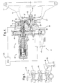
- Figure 2 shows a first embodiment of a hand wheel actuator having a stationary hub.
- Hand wheel 12 is rigidly connected via one or more spokes 22 to arm 24 via first shaft 71 integrally formed therewith. While first shaft 71 and arm 24 are shown as being integrally formed, they may of course be constructed from separate components.
- First shaft 71 includes a central opening 26 through which post 25 extends, and serves to transmit force from hand wheel 12 to upper shaft 13 via arm 24.
- Post 25 is fixed to actuator housing 30, supports stationary hub 15 at one end thereof, the hub being fixed by nut 32.
- Instrument cable 16 extends from hub 15 through channel 14 to additional electronics positioned behind the dashboard (not shown).
- arm 24 transmits force exerted on hand wheel 12 to upper shaft 13.
- Upper shaft 13 contains a torsion bar 38.
- Upper shaft 13 and torsion bar 38 are fixed with respect to each other at a first end 33 of upper shaft 13.
- torsion bar 38 is fixed to lower shaft 36.
- Upper shaft 13 and lower shaft 36 together make up steering shaft 55.
- Torque/position sensor 39 detects the displacement between upper shaft 13 and lower shaft 36 caused by torquing of torsion bar 38 and translates this into toque information.
- Torque/position sensor 39 also determines a displacement angle of upper shaft 13 and/or lower shaft 36 to indicate position.
- the torque and angular displacement signals are transmitted to electronic control unit (ECU) 20.
- ECU electronice control unit
- ECU 20 receives the torque and angular displacement signals, as well as other signals such as, for example, vehicular speed and sensors at road wheels 19 (Figure 1, only one shown) and outputs driving signals for road wheel steering actuator 17 ( Figure 1). ECU also uses feedback from one or more torque sensors in road wheel actuator 17 to calculate the necessary driver feedback torque. This calculation is translated into a motor input signal that is provided to motor 40. Motor 40 imparts a torque against lower shaft 36 via worm 42 mounted or formed into the output shaft of motor 40, and worm gear 44, which is fixed to lower shaft 36. Note that torque/position sensor provides torque feedback to ECU 20 for closed-loop control of driver feedback.
- Hand wheel actuator 10 includes a spring-biased mechanical return-to-center device 90. With this device, rotational motion of lower shaft 36 is transmitted to ball screw 54 via pin 51. As ball screw 54 rotates, ball nut 58 is permitted only to slide longitudinally. Spring adapter 92 is fixed to ball nut 58, telescoping over ball screw extension 64.
- Compression spring 95 is constrained between spring washers 93 and 94.
- Spring washer 93 is limited from moving right as seen in Figure 2 by either shoulder 91 of spring adapter 92 or shoulder 53 of housing 52.
- Spring washer 94 is limited from moving left as seen in Figure 2 by either nut 96 attached to end of spring adapter 92 or lip 99 of cover 98.
- ball nut 58 moves to the right from the center position shown in Figure 2, nut 96 and spring washer 94 move with it, while spring washer 93 remains fixed against shoulder 53 of housing 52. The spring compresses causing increased resistance the farther ball nut 58 is moved from center.
- rotational motion of hand wheel 12 is limited to less than 180° from center in either direction by housing 30, which supports post 25.
- arm 24 provides a low cost, reliable, and effective connection between the hand wheel 12 and upper shaft 13, while permitting hub 15 as well as electronics cables 16 to remain stationary.
- arm 24 provides a solid connection between hand wheel 12 and upper shaft 13, which reduces turning resistance and improves overall driver feel.
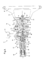
- Figure 3 shows a second embodiment.
- a hand wheel actuators including a fixed hub is configured such that the hand wheel is permitted to rotate in excess of 180° in either direction, e.g., they can provide a steering wheel rotation of ⁇ 540° rotation (i.e., one and one-half revolution in either direction) as in traditional mechanical steering systems.
- hand wheel 12 is fixed to first shaft 71, which includes conical gear 72.
- Conical gear 72 is fixed to first shaft 71 or formed integrally therewith, as shown.
- Conical gear 72 engages second conical gear 73, which is fixed to spindle 75 and supported by bearings 74.
- conical gear 72 and second conical gear 73 are arranged about 90 degrees with respect to each other, this is not a requirement, and other angles are possible. If a different angle is employed, the axis of upper shaft 13 may be angularly displaced, or some gear reduction may occur between first shaft 71 and upper shaft 13.
- Second conical gear 73 engages third conical gear 76, which is fixed to upper shaft 13.
- stopper 50 is provided to limit rotation. Stopper 50 operates as a positive travel end stop and comprises ball screw 54 connected to lower shaft 36 by pin 51. Ball nut 58 engages ball screw 54 and travels linearly along the axis of ball screw 54. Rotation of ball nut 58 is prevented by bosses 61, which slide in slots 56 formed in housing 52. Bumpers 62 are optionally provided in slots 56 to provide rapidly increased resistance at the positive travel limits, thereby improving steering feel.
- hand wheel rotates first shaft 71 which rotates conical gear 72.
- Conical gear 72, second conical gear 73, and third conical gear 76 are arranged series so that when conical gear 71 rotates in a first direction, conical gear 76 will rotate in an opposite direction around the common axis. Note that there is no requirement that the hand wheel axis and upper shaft axis be coincident. Using different sized gears or varying relative angles between them can customize the configuration of the actuator to any specific application.
- Figure 4 shows a third embodiment. Differences between the second and third embodiments will be described.
- spokes 22 of hand wheel 12 are integrally formed with shaft 81, which is supported by bearings 83.
- First gear 82 is fixed to shaft 81 and engages second gear 84, which is fixed to upper shaft 13.
- steering axis 86 and axis 87 of upper shaft 13 are parallel but not coincident.
- Motor 40 engages lower shaft 36 by means of a motor pulley 46, belt 47, and lower shaft pulley 48.
- This pulley/belt configuration has the advantage of quieter operation and no possibility of backlash resulting from worm 42 and worm gear 44 of previous embodiments, and therefore has the potential for improved performance.
- the third and second embodiment are structurally and functionally similar.
- Figure 5 shows a fourth embodiment which is similar to the third embodiment shown in Figure 4, with the exception that first gear 82 is an inside gear formed inside first shaft 71. First gear 82 engages second gear 84 which is fixed to upper shaft 13.
- Post support 31 which is fixed to housing 30, extends through the gap between first gear 82 and second gear 84 to fixedly support post 25 and thereby maintain hub 15 in a stationary position.
- Post support 31 also supports bearings 21 which rotatably support first shaft 71.
- Instrument cable 16 passes from hub 15 through post 25, through post support 31, and then to any associated electronic components (not shown).
- the fourth embodiment is structurally and functionally similar to the previous embodiment.
- Figure 6 shows a fifth embodiment of the invention.
- hand wheel 12 is mounted to a first shaft 71, which is supported by bearings 21 over post 25, and a steering pulley 27 is formed into or attached to first shaft 71.
- a steering belt 28 engages steering pulley 27 and upper shaft pulley 29 so that motion and force is transmitted from first shaft 71 to upper shaft 13.
- This pulley/belt configuration has the advantage of quieter operation and no possibility of backlash resulting from gear interactions of previous embodiments, and therefore has the potential for improved performance.
- the fifth embodiment is similar to the first and second embodiments.
- Figure 7 shows a sixth embodiment of the invention.
- shaft 71 is supported by bearings which are directly supported by housing 30, and hub 15 is supported by shaft 71 via bearings 23.
- Post 25 extends through shaft 71 and serves only as a conduit for instrument cable 16 and to maintain hub 15 in a fixed position, i.e., prevent hub 15 from rotating with shaft 71.
- Shaft 71 includes a steering pulley 27 mounted thereon which, along with pulley 29 on upper shaft 13 and steering belt 28, provide a means for placing first shaft 71 and upper shaft 13 into operable communication with each other.
- Other means such as those described herein with respect to previous embodiments can easily be used in place of steering belt 28.
- This embodiment includes torque/position sensor 39 and redundant position sensor 41 that directly measures the position of first shaft 71.
- Return-to-center device 110 shown in Figure 7 and schematically in Figure 8, includes a cam gear 120 mounted to an pin 122, which is positioned parallel to lower shaft 36.
- Lower shaft 36 includes a pinion 123 that interfaces with internal gear teeth 124.
- Cam gear 120 includes a camming surface 126.
- a cam follower 112 is fixed to housing 30 and positioned to engage camming surface 126.
- Cam follower 112 comprises a housing 111 that is generally cylindrically shaped and containing spring 117.
- Spring 117 is in compression and biases cam 116 towards camming surface 126.
- Cam 116 includes a bearing surface 118 formed from a low friction material such as an acetal resin.
- An adjustable cam stop 114 is threaded to housing 111 on a side opposite said cam to adjust the compression force exerted by spring 117.
- Cam surface 126 is represented in Figure 8 as circular that has a center displaced from the center of rotation defined by pin 122. However, the cam may have other shapes corresponding to an optimized return-to center feel for the driver.
- Cam gear 120 includes stop surfaces 128 to prevent cam gear 120 from rotating past a selected point, thereby also providing an absolute stop function as discussed above with respect to the second embodiment shown in Figure 3.
Landscapes
- Engineering & Computer Science (AREA)
- Chemical & Material Sciences (AREA)
- Combustion & Propulsion (AREA)
- Transportation (AREA)
- Mechanical Engineering (AREA)
- Power Steering Mechanism (AREA)
- Steering Control In Accordance With Driving Conditions (AREA)
Abstract
Description
- This disclosure relates to a hand wheel actuator for a steer-by-wire system of an vehicle. More particularly, the disclosure relates to a hand wheel actuator having a stationary hub.
- Automobiles are conventionally equipped with a pair of front road wheels that are steered to enable the vehicle to turn left and right as it maneuvers on land. It is also known to provide actuators for steering rear wheels in automobiles. Vehicle steering systems commonly employ a mechanical connection between the driver-operated hand wheel and the front road wheels of an automotive vehicle. As the driver rotates the hand wheel, a mechanical linkage through the vehicle's tie-rods actuate the road wheels sometimes with the assistance of a power assist steering motor or hydraulic piston. The term, "hand wheel" as used herein refers to a driver-operated rotating steering input device, but it need not be round or wheel shaped, though that is the most common configuration.
- Recently, steer-by-wire steering systems have been introduced into automotive vehicles to provide road wheel steering function. Included in a typical steer-by-wire steering system is a hand wheel actuator for monitoring the angular position of the steering wheel, and road wheel motor actuators, which are controlled by controllers in response to tracking the sensed angular displacement of the hand wheel from a central or other position. In contrast to prior steering systems, the steer-by-wire steering system does not employ a mechanical linkage between the steering wheel and the individual road wheels. Exemplary of such known steer-by-wire systems is commonly-assigned U.S. Patent 6,176,341, issued January 23, 20001 to Ansari, which is incorporated herein by reference in its entirety.
- Along with the advent of steer-by-wire systems, automobile purchasers are always expecting an increased level of driver comfort and convenience. The desirability of placing some instruments, such as environmental and audio system controls on or near the steering wheel has long been recognized. Such controls are currently placed in various locations around the steering wheel, such as along a spoke or integrated in a multi-function stalk switch. As the sophistication of automobile electronics increases, and with the increased popularity of such systems as mobile communications, Global Positioning Satellite (GPS) systems and electronic maps, the locations available to place such controls and displays are not adequate, particularly since any control or display mounted on the hub or spoke of the steering wheel (over the airbag, for example) would turn with the steering wheel and therefore not be useful unless traveling in a relatively straight line.
- Accordingly, there is perceived a need for a steering wheel assembly having a stationary hub so that electronic controls and displays are viewable and conveniently provided.
- The above-discussed and other drawbacks and deficiencies of the prior art are overcome or alleviated by providing a hand wheel actuator having a stationary hub, including a housing supporting a first shaft via bearings such that it is rotatable about its own axis. The first shaft has an upper end configured for attaching a hand wheel. The actuator also includes a position sensor for detecting an angular displacement of the first shaft from a selected origin and producing a signal indicative of said angular displacement and an electric motor in operative communication with the first shaft for providing feedback to a driver. A steering post is maintained in a fixed position with respect to the housing for maintaining the hub in a fixed position centrally of said hand wheel, so that the hub faces the driver when said hand wheel is operated. The steering post extends along an axis of rotation of the hand wheel and through the first shaft, which is fixed to the hand wheel and rotates therewith.
- The above-discussed and other features and advantages of the present invention will be appreciated and understood by those skilled in the art from the following detailed description and drawings.
- The present invention will now be described by way of example with reference to the accompanying drawings, in which:
- Figure 1 shows a schematic overview of a steer-by-wire system;
- Figure 2 shows a first embodiment of a hand wheel actuator having a stationary hub;
- Figure 3 shows a second embodiment of a hand wheel actuator having a stationary hub;
- Figure 4 shows a third embodiment of a hand wheel actuator having a stationary hub;
- Figure 5 shows a fourth embodiment of a hand wheel actuator having a stationary hub;
- Figure 6 shows a fifth embodiment of a hand wheel actuator having a stationary hub;
- Figure 7 shows a sixth embodiment of a hand wheel actuator having a stationary hub; and
- Figure 8 shows a schematic view of a return-to-center device of Figure 7.
- Figure 1 shows a schematic overview of an exemplary steer-by-wire system for a vehicle. Driver input is made to
hand wheel 12, which is connected byupper shaft 13 tohand wheel actuator 10.Hand wheel actuator 10 includes a position sensor for detecting the angular displacement ofhand wheel 12. The position sensor output is directed toelectronic control unit 20, which includes a microprocessor and other assorted electronic components well known in the field of electronic control for providing memory, input/output, and processing functions.Electronic control unit 20 receives signals from hand wheel position sensors inhand wheel actuator 10 and determines what signals, if any, to send toroad wheel actuator 17 so that the position of road wheels 19 (only one shown) properly correspond with the position ofhand wheel 12.Road wheel actuator 17 controls the steering position ofroad wheels 19 by means of a tie-rod 18. -
Road wheel actuator 17 includes torque or strain sensors to measure force required byroad wheel actuator 17 to rotate and maintainroad wheels 19 in their desired position. Output from road wheel torque sensors (not shown) is transmitted toelectronic control unit 20, which then transmits driver feedback information tohand wheel actuator 10.Hand wheel actuator 10 includes an electric motor or other actuator to provide force-feedback tosteering wheel 12, thus giving the driver feedback as to the road conditions.Hand wheel actuator 10 may also include a torque sensor for providing a signal to the electronic control unit to ensure that the driver is receiving the correct amount of driver feedback. - Figure 2 shows a first embodiment of a hand wheel actuator having a stationary hub.
Hand wheel 12 is rigidly connected via one ormore spokes 22 toarm 24 viafirst shaft 71 integrally formed therewith. Whilefirst shaft 71 andarm 24 are shown as being integrally formed, they may of course be constructed from separate components.First shaft 71 includes acentral opening 26 through whichpost 25 extends, and serves to transmit force fromhand wheel 12 toupper shaft 13 viaarm 24.Post 25 is fixed toactuator housing 30, supportsstationary hub 15 at one end thereof, the hub being fixed bynut 32.Instrument cable 16 extends fromhub 15 throughchannel 14 to additional electronics positioned behind the dashboard (not shown). - As noted previously,
arm 24 transmits force exerted onhand wheel 12 toupper shaft 13.Upper shaft 13 contains atorsion bar 38.Upper shaft 13 andtorsion bar 38 are fixed with respect to each other at afirst end 33 ofupper shaft 13. At a lower end,torsion bar 38 is fixed tolower shaft 36.Upper shaft 13 andlower shaft 36 together make upsteering shaft 55. Torque/position sensor 39 detects the displacement betweenupper shaft 13 andlower shaft 36 caused by torquing oftorsion bar 38 and translates this into toque information. Torque/position sensor 39 also determines a displacement angle ofupper shaft 13 and/orlower shaft 36 to indicate position. The torque and angular displacement signals are transmitted to electronic control unit (ECU) 20. ECU 20 receives the torque and angular displacement signals, as well as other signals such as, for example, vehicular speed and sensors at road wheels 19 (Figure 1, only one shown) and outputs driving signals for road wheel steering actuator 17 (Figure 1). ECU also uses feedback from one or more torque sensors inroad wheel actuator 17 to calculate the necessary driver feedback torque. This calculation is translated into a motor input signal that is provided tomotor 40.Motor 40 imparts a torque againstlower shaft 36 viaworm 42 mounted or formed into the output shaft ofmotor 40, andworm gear 44, which is fixed tolower shaft 36. Note that torque/position sensor provides torque feedback toECU 20 for closed-loop control of driver feedback. -
Hand wheel actuator 10 includes a spring-biased mechanical return-to-center device 90. With this device, rotational motion oflower shaft 36 is transmitted to ball screw 54 viapin 51. As ball screw 54 rotates,ball nut 58 is permitted only to slide longitudinally.Spring adapter 92 is fixed toball nut 58, telescoping overball screw extension 64. -
Compression spring 95 is constrained betweenspring washers Spring washer 93 is limited from moving right as seen in Figure 2 by eithershoulder 91 ofspring adapter 92 orshoulder 53 ofhousing 52.Spring washer 94 is limited from moving left as seen in Figure 2 by eithernut 96 attached to end ofspring adapter 92 orlip 99 ofcover 98. Whenball nut 58 moves to the right from the center position shown in Figure 2,nut 96 andspring washer 94 move with it, whilespring washer 93 remains fixed againstshoulder 53 ofhousing 52. The spring compresses causing increased resistance thefarther ball nut 58 is moved from center. On the other hand, whenball nut 58 moves left from the central position shown in Figure 2,spring washer 93 is pushed to the left byshoulder 91 ofspring adapter 92 whilespring washer 94 remains fixed againstlip 99 ofcover 98. The spring again compresses, causing increased resistance thefarther ball nut 58 is moved from center. A mechanical return-to-center device 90 will bias the steering wheel towards the center position at all times. Aball plunger 55 may also be employed for improving driver feel at center.Ball plunger 55 cams against the outer surface ofspring adapter 92, which is shaped for a desirable center-feel. - With the embodiment shown in Figure 2, rotational motion of
hand wheel 12 is limited to less than 180° from center in either direction byhousing 30, which supportspost 25. Although so limited,arm 24 provides a low cost, reliable, and effective connection between thehand wheel 12 andupper shaft 13, while permittinghub 15 as well aselectronics cables 16 to remain stationary. Furthermore,arm 24 provides a solid connection betweenhand wheel 12 andupper shaft 13, which reduces turning resistance and improves overall driver feel. - Figure 3 shows a second embodiment. In this embodiment, as in the remaining embodiments to be described below, a hand wheel actuators including a fixed hub is configured such that the hand wheel is permitted to rotate in excess of 180° in either direction, e.g., they can provide a steering wheel rotation of ± 540° rotation (i.e., one and one-half revolution in either direction) as in traditional mechanical steering systems. In this embodiment,
hand wheel 12 is fixed tofirst shaft 71, which includesconical gear 72.Conical gear 72 is fixed tofirst shaft 71 or formed integrally therewith, as shown.Conical gear 72 engages secondconical gear 73, which is fixed tospindle 75 and supported bybearings 74. Whileconical gear 72 and secondconical gear 73 are arranged about 90 degrees with respect to each other, this is not a requirement, and other angles are possible. If a different angle is employed, the axis ofupper shaft 13 may be angularly displaced, or some gear reduction may occur betweenfirst shaft 71 andupper shaft 13. - Second
conical gear 73 engages thirdconical gear 76, which is fixed toupper shaft 13. The remaining apparatus is structurally and functionally similar to the first embodiment previously described. However, sincehousing 30 does not limit rotation ofhand wheel 12,stopper 50 is provided to limit rotation.Stopper 50 operates as a positive travel end stop and comprisesball screw 54 connected tolower shaft 36 bypin 51.Ball nut 58 engagesball screw 54 and travels linearly along the axis ofball screw 54. Rotation ofball nut 58 is prevented bybosses 61, which slide inslots 56 formed inhousing 52.Bumpers 62 are optionally provided inslots 56 to provide rapidly increased resistance at the positive travel limits, thereby improving steering feel. - In operation, hand wheel rotates
first shaft 71 which rotatesconical gear 72.Conical gear 72, secondconical gear 73, and thirdconical gear 76 are arranged series so that whenconical gear 71 rotates in a first direction,conical gear 76 will rotate in an opposite direction around the common axis. Note that there is no requirement that the hand wheel axis and upper shaft axis be coincident. Using different sized gears or varying relative angles between them can customize the configuration of the actuator to any specific application. -
Upper shaft 13,torsion bar 38,lower shaft 36, torsion/position sensor 39,electronic control unit 20,worm gear 44,pin 51,ball screw 54,ball nut 58 and return-to-center device 90 all operate as described above with respect to the first embodiment shown in Figure 2. Asball nut 58 slides to the left and right as seen in Figure 3, it engagesbumpers 62 positioned at either end ofslots 56, thereby limiting the linear movement ofball nut 58. Whenball nut 58 reaches one limit of movement, it prevents further rotation ofball screw 54, which prevents further rotation oflower shaft 36,upper shaft 13, thirdconical gear 76, secondconical gear 73,conical gear 72,first shaft 71 and thereforehand wheel 12. Preferably,slots 56 are sized to permit a maximum rotation of 540° (one and a half revolutions) from center in either direction. - Figure 4 shows a third embodiment. Differences between the second and third embodiments will be described. In this embodiment,
spokes 22 ofhand wheel 12 are integrally formed withshaft 81, which is supported bybearings 83.First gear 82 is fixed toshaft 81 and engagessecond gear 84, which is fixed toupper shaft 13. As can be seen, steeringaxis 86 andaxis 87 ofupper shaft 13 are parallel but not coincident.Motor 40 engageslower shaft 36 by means of amotor pulley 46,belt 47, andlower shaft pulley 48. This pulley/belt configuration has the advantage of quieter operation and no possibility of backlash resulting fromworm 42 andworm gear 44 of previous embodiments, and therefore has the potential for improved performance. In other respects the third and second embodiment are structurally and functionally similar. - Figure 5 shows a fourth embodiment which is similar to the third embodiment shown in Figure 4, with the exception that
first gear 82 is an inside gear formed insidefirst shaft 71.First gear 82 engagessecond gear 84 which is fixed toupper shaft 13. - Because of
second gear 84 is somewhat smaller thanfirst gear 82, steeringaxis 86 is just offset fromaxis 87 ofupper shaft 13.Post support 31, which is fixed tohousing 30, extends through the gap betweenfirst gear 82 andsecond gear 84 to fixedly supportpost 25 and thereby maintainhub 15 in a stationary position.Post support 31 also supportsbearings 21 which rotatably supportfirst shaft 71.Instrument cable 16 passes fromhub 15 throughpost 25, throughpost support 31, and then to any associated electronic components (not shown). In all other respects the fourth embodiment is structurally and functionally similar to the previous embodiment. - Figure 6 shows a fifth embodiment of the invention. In this embodiment,
hand wheel 12 is mounted to afirst shaft 71, which is supported bybearings 21 overpost 25, and a steeringpulley 27 is formed into or attached tofirst shaft 71. A steeringbelt 28 engages steeringpulley 27 andupper shaft pulley 29 so that motion and force is transmitted fromfirst shaft 71 toupper shaft 13. This pulley/belt configuration has the advantage of quieter operation and no possibility of backlash resulting from gear interactions of previous embodiments, and therefore has the potential for improved performance. In other respects, the fifth embodiment is similar to the first and second embodiments. - Figure 7 shows a sixth embodiment of the invention. In this embodiment, rather than post 25 providing support for
shaft 71 as in previous embodiments,shaft 71 is supported by bearings which are directly supported byhousing 30, andhub 15 is supported byshaft 71 viabearings 23.Post 25 extends throughshaft 71 and serves only as a conduit forinstrument cable 16 and to maintainhub 15 in a fixed position, i.e., preventhub 15 from rotating withshaft 71. -
Shaft 71 includes a steeringpulley 27 mounted thereon which, along withpulley 29 onupper shaft 13 and steeringbelt 28, provide a means for placingfirst shaft 71 andupper shaft 13 into operable communication with each other. Other means, such as those described herein with respect to previous embodiments can easily be used in place of steeringbelt 28. This embodiment includes torque/position sensor 39 andredundant position sensor 41 that directly measures the position offirst shaft 71. - Return-to-
center device 110, shown in Figure 7 and schematically in Figure 8, includes acam gear 120 mounted to anpin 122, which is positioned parallel tolower shaft 36.Lower shaft 36 includes apinion 123 that interfaces withinternal gear teeth 124.Cam gear 120 includes acamming surface 126. - A
cam follower 112 is fixed tohousing 30 and positioned to engagecamming surface 126.Cam follower 112 comprises ahousing 111 that is generally cylindrically shaped and containingspring 117.Spring 117 is in compression andbiases cam 116 towardscamming surface 126.Cam 116 includes abearing surface 118 formed from a low friction material such as an acetal resin. Anadjustable cam stop 114 is threaded tohousing 111 on a side opposite said cam to adjust the compression force exerted byspring 117. -
Cam surface 126 is represented in Figure 8 as circular that has a center displaced from the center of rotation defined bypin 122. However, the cam may have other shapes corresponding to an optimized return-to center feel for the driver. -
Cam gear 120 includes stop surfaces 128 to preventcam gear 120 from rotating past a selected point, thereby also providing an absolute stop function as discussed above with respect to the second embodiment shown in Figure 3. - As used herein, the terms, "first", "second", "third", etc., are used only to distinguish among various similar elements and not to designate an order in terms of position or importance.
- While preferred embodiments have been shown and described, various modifications and substitutions may be made thereto without departing from the spirit and scope of the invention. Accordingly, it is to be understood that the present invention has been described by way of illustration and not limitation.
Claims (29)
- A hand wheel (12) actuator comprising:a housing (30);a first shaft (71, 81) having an upper end configured for attaching a hand wheel (12), said first shaft (71, 81) being supported by said housing (30) via bearings (21) such that it is rotatable about its own axis;a position sensor (39) for detecting an angular displacement of the first shaft (71, 81) from a selected origin and producing a signal indicative of said angular displacement;an electric motor (40) in operative communication with the first shaft (71, 81) for providing force feedback to a driver; anda steering post (25) maintained in a fixed position with respect to the housing (30) for maintaining a steering hub (15) in a fixed position centrally of said hand wheel (12), said steering hub (15) facing the driver when said hand wheel (12) is operated, said steering post (25) extending along an axis of rotation of said hand wheel (12) and through said first shaft (71, 81), said first shaft (71, 81) being fixed to said hand wheel (12) and rotating therewith.
- The hand wheel (12) actuator of claim 1, said steering hub (15) including electronic instruments, said steering post (25) being hollow and serving as a conduit for an instrument cable (16) extending to said instruments.
- The hand wheel (12) actuator of claim 1, said steering post (25) being attached and fixed directly to said housing (30).
- The hand wheel (12) actuator of claim 1, said steering post (25) being attached directly to a post support (31) which is fixed to said housing (30).
- The hand wheel (12) actuator of claim 3 wherein said first shaft (71, 81) includes a lower section having an increased diameter and an internal gear (82), said internal gear (82) being engaged to a pinion (84) mounted to an upper shaft (13); said post support (31) extending between said internal gear (82) and said pinion (84) for supporting and maintaining said steering post (25) in a fixed position with respect to said housing (30).
- The hand wheel (12) actuator of claim 1, said first shaft (71, 81) being supported by said steering post (25) via said bearings (21) which allow relative rotation between said steering post (25) and said first shaft (71, 81).
- The hand wheel (12) actuator of claim 6 further comprising:an arm (24) extending from said first shaft (71, 81) to a steering shaft (55), said steering shaft (55) and said first shaft (71, 81) being coaxial and said arm (24) being fixed and connecting said steering shaft (55) with said first shaft (71, 81); said position sensor (39) directly sensing a position of said steering shaft (55).
- The hand wheel (12) actuator of claim 7 wherein said steering shaft (55) comprises an upper shaft (13) and a lower shaft (36), said upper shaft (13) and said lower shaft (36) being coupled by a torsion bar (38) and said position sensor (39) is a torque/position sensor (39), said torque/position sensor (39) utilizing a displacement between said upper shaft (13) and said lower shaft (36) to determine a torque on said steering shaft (55), said electric motor (40) being operatively connected to said lower shaft (36).
- The hand wheel (12) actuator of claim 7 further comprising a return-to-center device (90,110) operatively connected to said steering shaft (55), said return-to-center device (90,110) applying a mechanical force to said steering shaft (55) when said hand wheel (12) is not in a centered position, said mechanical force biasing said hand wheel (12) toward said centered position.
- The hand wheel (12) actuator of claim 6, said first shaft (71, 81) being in mechanical communication with a steering shaft (55), said position sensor (39) directly sensing a position of the steering shaft (55).
- The hand wheel (12) actuator of claim 10 wherein said first shaft (71, 81) has a first gear (72, 82) and said steering shaft (55) has a second gear (76, 84), said first gear (72, 82) and said second gear (76, 84) being in operative communication with each other such that rotation of one of said first gear (72, 82) and said second gear (76, 84) causes a corresponding rotation of another of said first gear (72, 82) and said second gear (76, 84).
- The hand wheel (12) actuator of claim 11 wherein said first gear (72, 82) is a conical gear and said second gear (76, 84) is a conical gear.
- The hand wheel (12) actuator of claim 12 wherein said first gear (72, 82) and said second gear (76, 84) have substantially coincident axes of rotation.
- The hand wheel (12) actuator of claim 11 wherein said first gear (72, 82) and said second gear (76, 84) engage each other and have parallel axes of rotation.
- The hand wheel (12) actuator of claim 10 wherein said first shaft (71, 81) has a first pulley (27) and said steering shaft (55) has a second pulley (29), said hand wheel (12) actuator further comprising a belt that engages said first pulley (27) and said second pulley (29) thereby placing said steering shaft (55) and said first shaft (71, 81) in operative communication with each other.
- The hand wheel (12) actuator of claim 10 wherein said steering shaft (55) comprises an upper shaft (13) and a lower shaft (36), said upper shaft (13) and said lower shaft (36) being coupled by a torsion bar (38) and said position sensor (39) is a torque/position sensor (39), said torque/position sensor (39) utilizing a displacement between said upper shaft (13) and said lower shaft (36) to determine a torque on said steering shaft (55), said electric motor (40) being operatively connected to said lower shaft (36).
- The hand wheel (12) actuator of claim 16 further comprising a redundant position sensor (41) directly sensing a position of said first shaft (71, 81).
- The hand wheel (12) actuator of claim 10 further comprising a mechanical return-to-center and positive stop device (90, 110) that positively limits rotation of said hand wheel (12) to a selected maximum angle or rotation in either direction and provides a mechanical force to said steering shaft (55) when said hand wheel (12) is not in a centered position, said mechanical force biasing said hand wheel (12) toward said centered position.
- The hand wheel (12) actuator of claim 18 wherein said mechanical return-to-center and positive stop device (90, 110) acts directly on said steering shaft (55).
- The hand wheel (12) actuator of claim 18 wherein said mechanical return-to-center and positive stop device (90, 110) comprises a ball screw and spring mechanism (90).
- The hand wheel (12) actuator of claim 18 wherein said mechanical return-to-center and positive stop device (90, 110) comprises a spring-biased cam (112) and camming surface (126) linked to said steering shaft (55).
- The hand wheel (12) actuator of claim 1 wherein said first shaft (71, 81) is supported by said housing (30) via said bearings (21) which allow rotation of the first shaft (71, 81) with respect to said housing (30); said steering post (25) extending through said first shaft (71, 81) to maintain said steering hub (15) in said fixed position.
- The hand wheel (12) actuator of claim 22, said first shaft (71, 81) being in mechanical communication with a steering shaft (55), said position sensor (39) directly sensing a position of the steering shaft (55).
- The hand wheel (12) actuator of claim 23 wherein said first shaft (71, 81) has a first pulley (27) and said steering shaft (55) has a second pulley (29), said hand wheel (12) actuator further comprising a belt that engages said first pulley (27) and said second pulley (29) thereby placing said steering shaft (55) and said first shaft (71, 81) in operative communication with each other.
- The hand wheel (12) actuator of claim 10 wherein said steering shaft (55) comprises an upper shaft (13) and a lower shaft (36), said upper shaft (13) and said lower shaft (36) being coupled by a torsion bar (38); said position sensor (39) being a torque/position sensor (39) that utilizes a displacement between said upper shaft (13) and said lower shaft (36) to determine a torque on said steering shaft (55), said electric motor (40) being operatively connected to said lower shaft (36).
- The hand wheel (12) actuator of claim 24 further comprising a redundant position sensor (41) directly sensing a position of said first shaft (71, 81).
- The hand wheel (12) actuator of claim 23 further comprising a redundant position sensor (41) directly sensing a position of said first shaft (71, 81).
- The hand wheel (12) actuator of claim 23 further comprising a mechanical retum-to-center and positive stop device that positively limits rotation of said hand wheel (12) to a selected maximum angle or rotation in either direction and provides a mechanical force to said steering shaft (55) when said hand wheel (12) is not in a centered position, said mechanical force biasing said hand wheel (12) toward said centered position.
- The hand wheel (12) actuator of claim 18 wherein said mechanical return-to-center and positive stop device (90, 110) comprises a spring-biased cam (112) and camming surface (126) linked to said steering shaft (55).
Applications Claiming Priority (2)
| Application Number | Priority Date | Filing Date | Title |
|---|---|---|---|
| US10/091,079 US6892605B2 (en) | 2002-03-04 | 2002-03-04 | Hand wheel actuator having stationary hub |
| US91079 | 2005-03-28 |
Publications (2)
| Publication Number | Publication Date |
|---|---|
| EP1342639A2 true EP1342639A2 (en) | 2003-09-10 |
| EP1342639A3 EP1342639A3 (en) | 2004-01-02 |
Family
ID=27754002
Family Applications (1)
| Application Number | Title | Priority Date | Filing Date |
|---|---|---|---|
| EP03075462A Withdrawn EP1342639A3 (en) | 2002-03-04 | 2003-02-18 | Hand wheel actuator having stationary hub |
Country Status (2)
| Country | Link |
|---|---|
| US (1) | US6892605B2 (en) |
| EP (1) | EP1342639A3 (en) |
Cited By (21)
| Publication number | Priority date | Publication date | Assignee | Title |
|---|---|---|---|---|
| WO2005100097A1 (en) * | 2004-03-31 | 2005-10-27 | Thyssenkrupp Presta Ag | Airbag assembly, gear and operating method for said assembly |
| WO2005102815A1 (en) * | 2004-04-20 | 2005-11-03 | Autoliv Development Ab | Steer-by-wire steering wheel unit with integrated airbag module |
| EP1669254A1 (en) * | 2004-12-13 | 2006-06-14 | Key Safety Systems, Inc. | Static driver airbag module assembly |
| FR2889150A1 (en) * | 2005-07-28 | 2007-02-02 | Renault Sas | Mechanism for restoring effort to steer-by-wire steering wheel has cam with continuously varying profile interacting with spring-loaded pusher on moving carriage |
| DE102005053183A1 (en) * | 2005-11-03 | 2007-05-10 | Valeo Schalter Und Sensoren Gmbh | Assembly for a steering system of a motor vehicle |
| DE102006003429A1 (en) * | 2006-01-25 | 2007-07-26 | Zf Lenksysteme Gmbh | Steering shaft for steering wheel, has intermediate shaft gear wheels on intermediate shaft, which are engaged with fixed steering gear shaft wheel on steering gear shaft |
| FR2914722A1 (en) * | 2007-04-05 | 2008-10-10 | Peugeot Citroen Automobiles Sa | Ball screw mechanism for motor vehicle steering assembly, has channels formed so that screw forming part is animated with rotation movement to move nut forming part in translation causing rotation movement of other screw forming part |
| EP2058210A1 (en) * | 2007-11-06 | 2009-05-13 | Honda Motor Co., Ltd. | Electric power steering device |
| US7931296B2 (en) | 2007-12-15 | 2011-04-26 | Hyundai Motor Company | Vehicle steering system including irrotational airbag module |
| ITBO20110644A1 (en) * | 2011-11-10 | 2013-05-11 | A M A S P A | STEERING DEVICE |
| WO2012076175A3 (en) * | 2010-12-10 | 2013-12-05 | Thyssenkrupp Presta Ag | Manual torque adjuster |
| KR101459429B1 (en) | 2009-12-03 | 2014-11-07 | 현대자동차 주식회사 | Turn stopper for steer-by-wire system |
| DE102017207272A1 (en) * | 2017-04-28 | 2018-10-31 | Volkswagen Aktiengesellschaft | Steering handle |
| EP3960584A1 (en) * | 2020-08-28 | 2022-03-02 | Lotus Tech Innovation Centre GmbH | Steer-by-wire steering system having an off-axis steering system support column provided with a steering wheel rotation limiting device |
| EP3960583A1 (en) * | 2020-08-28 | 2022-03-02 | Lotus Tech Innovation Centre GmbH | Steer-by-wire steering system having an off-axis steering system support column |
| EP3960582A1 (en) * | 2020-08-28 | 2022-03-02 | Lotus Tech Innovation Centre GmbH | Steer-by-wire steering system comprising an outer rotor torque feedback device |
| EP3960585A1 (en) * | 2020-08-28 | 2022-03-02 | Lotus Tech Innovation Centre GmbH | Steer-by-wire steering system comprising a steering wheel rotation limiting device |
| US11459030B2 (en) | 2018-08-28 | 2022-10-04 | Volkswagen Aktiengesellschaft | Apparatus for measuring a torque in a force-feedback actuator for a steer-by-wire steering system |
| WO2024088473A1 (en) | 2022-10-28 | 2024-05-02 | Schaeffler Technologies AG & Co. KG | Adjusting unit of a steering column |
| WO2024088456A1 (en) | 2022-10-28 | 2024-05-02 | Schaeffler Technologies AG & Co. KG | Adjusting unit of a steering column |
| DE102022133669A1 (en) | 2022-10-28 | 2024-05-08 | Schaeffler Technologies AG & Co. KG | Adjustment unit of a steering column |
Families Citing this family (33)
| Publication number | Priority date | Publication date | Assignee | Title |
|---|---|---|---|---|
| US6820713B2 (en) * | 2002-07-17 | 2004-11-23 | Delphi Technologies, Inc. | Hand wheel actuator with steering-feel enhancement |
| DE10353266B4 (en) * | 2003-11-14 | 2013-02-21 | Süd-Chemie Ip Gmbh & Co. Kg | Lithium iron phosphate, process for its preparation and its use as electrode material |
| DE102004059461A1 (en) * | 2004-12-10 | 2006-06-14 | Zf Lenksysteme Gmbh | steering |
| US7648004B1 (en) * | 2005-03-14 | 2010-01-19 | Novariant Inc. | Steering wheel control mechanism |
| EP1707469A1 (en) * | 2005-04-01 | 2006-10-04 | Key Safety Systems, Inc. | Steering wheel with stationary hub mounted portion |
| EP1990244A1 (en) * | 2007-05-09 | 2008-11-12 | Key Safety Systems, Inc. | Steering wheel assembly with stationary central portion |
| ITBO20070595A1 (en) * | 2007-08-29 | 2009-02-28 | Ferrari Spa | FRONT AIRBAG FOR A ROAD VEHICLE |
| JP2009119894A (en) * | 2007-11-12 | 2009-06-04 | Toyota Motor Corp | Vehicle steering device |
| DE202008008395U1 (en) * | 2008-05-15 | 2009-06-18 | Takata-Petri Ag | Steering device for a motor vehicle with a steering wheel and a superposition gear |
| US20100175499A1 (en) * | 2009-01-09 | 2010-07-15 | Ford Global Technologies, Llc | Vehicle steering wheel assembly |
| DE102013014133B3 (en) * | 2013-08-23 | 2014-10-30 | Audi Ag | steering stop |
| EP3118083B1 (en) * | 2014-03-11 | 2019-11-20 | Guangdong Hua'chan Research Institute of Intelligent Transportation System Co., Ltd. | Steering wheel |
| US9302701B2 (en) * | 2014-08-11 | 2016-04-05 | Gates Corporation | Vehicle steering system transmission |
| US20160137225A1 (en) * | 2014-11-19 | 2016-05-19 | Steering Solutions Ip Holding Corporation | Handwheel position detection system |
| EP3025929B1 (en) * | 2014-11-28 | 2017-06-14 | Aktiebolaget SKF | User interface actuator for a pilot-by-wire system |
| US10589774B2 (en) | 2015-05-01 | 2020-03-17 | Steering Solutions Ip Holding Corporation | Counter rotation steering wheel |
| US20160375931A1 (en) | 2015-06-25 | 2016-12-29 | Steering Solutions Ip Holding Corporation | Rotation control system for a steering wheel and method |
| US10160472B2 (en) * | 2015-10-20 | 2018-12-25 | Steering Solutions Ip Holding Corporation | Steering column with stationary hub |
| US10160473B2 (en) | 2016-09-13 | 2018-12-25 | Steering Solutions Ip Holding Corporation | Steering column decoupling system |
| KR102126225B1 (en) * | 2018-12-19 | 2020-06-25 | 주식회사 만도 | Steering Apparatus for Vehicle |
| SE1950156A1 (en) | 2019-02-11 | 2020-08-12 | Rybeck Marin Consult Ab | Motorboat fly-by-wire steering wheel hub |
| US11407436B2 (en) * | 2019-03-04 | 2022-08-09 | Byton North America Corporation | Steering wheel with fixed center |
| DE102019204913A1 (en) * | 2019-04-05 | 2020-10-08 | Zf Friedrichshafen Ag | Method and device for operating a steering system of a motor vehicle, as well as a control device and steering system |
| AT522442B1 (en) * | 2019-11-08 | 2020-11-15 | Ivan Tochev | Arrangement of a steering device |
| KR102786792B1 (en) * | 2020-08-25 | 2025-03-31 | 에이치엘만도 주식회사 | Steer-by-wire type steering apparatus |
| US11661099B2 (en) | 2021-02-11 | 2023-05-30 | Ford Global Technologies, Llc | Handwheel actuator modular interface |
| CN119928728A (en) * | 2021-04-19 | 2025-05-06 | 群创光电股份有限公司 | Safety airbag module arranged adjacent to display module and vehicle including the same |
| CN113415338B (en) * | 2021-07-12 | 2022-11-04 | 上海汽车工业(集团)总公司 | Steering-by-wire road sensing feedback device |
| US20240300569A1 (en) * | 2021-07-13 | 2024-09-12 | Hangzhou Kingway Technology Co., Ltd. | Retractable steering wheel arrangement for a steer-by-wire steering system |
| WO2023284948A1 (en) * | 2021-07-13 | 2023-01-19 | Lotus Tech Innovation Centre Gmbh | Retractable steering wheel arrangement with non-planar steering wheel rim |
| SE546934C2 (en) * | 2023-05-25 | 2025-03-11 | Chassis Autonomy Sba Ab | Handwheel actuator and steering wheel armature assembly for a steer-by-wire steering assembly |
| US12351233B2 (en) * | 2023-11-08 | 2025-07-08 | Steering Solutions Ip Holding Corporation | Steer by wire steering column with stationary wheel hub |
| CN119037534B (en) * | 2024-08-27 | 2025-08-29 | 浙江擎动汽车安全系统有限公司 | A worm-type wire-controlled steering system and its control system |
Citations (1)
| Publication number | Priority date | Publication date | Assignee | Title |
|---|---|---|---|---|
| US6176341B1 (en) | 1999-02-01 | 2001-01-23 | Delphi Technologies, Inc. | Vehicle steering system having master/slave configuration and method therefor |
Family Cites Families (22)
| Publication number | Priority date | Publication date | Assignee | Title |
|---|---|---|---|---|
| US4674352A (en) | 1983-12-29 | 1987-06-23 | Kabushiki Kaisha Tokai Rika Denki Seisakusho | Steering wheel device |
| JPH0798490B2 (en) * | 1986-02-06 | 1995-10-25 | 本田技研工業株式会社 | Electric power steering device |
| US4825972A (en) * | 1986-02-25 | 1989-05-02 | Honda Giken Kogyo Kabushiki Kaisha | Steering system for vehicles |
| US4771846A (en) | 1986-09-22 | 1988-09-20 | Trw Inc. | Apparatus for establishing steering feel |
| JPS6343846A (en) | 1987-02-18 | 1988-02-24 | Tokai Rika Co Ltd | Steering signal transmitter |
| CA1318833C (en) * | 1988-10-03 | 1993-06-08 | T. Jack Oki | Multi function steering mechanism for a motor vehicle |
| JP3554841B2 (en) | 1997-02-07 | 2004-08-18 | 光洋精工株式会社 | Car steering system |
| FR2774056B1 (en) | 1998-01-26 | 2000-04-21 | Ecia Equip Composants Ind Auto | STEERING SYSTEM FOR MOTOR VEHICLE |
| FR2793752B1 (en) * | 1999-05-17 | 2001-06-29 | Lemforder Nacam Sa | ELECTRIC AND MECHANICAL STEERING DEVICE OF MOTOR VEHICLE |
| JP2000355278A (en) * | 1999-06-14 | 2000-12-26 | Thk Co Ltd | Ball screw for steering and power steering device using the ball screw for steering |
| DE29915559U1 (en) * | 1999-09-03 | 2000-01-13 | TRW Fahrwerksysteme GmbH & Co KG, 40547 Düsseldorf | Steering system for a vehicle |
| DE10020085C1 (en) | 2000-04-22 | 2001-07-26 | Daimler Chrysler Ag | Steering wheel unit for vehicle includes magnetic force transmission as coupling medium |
| DE10036281A1 (en) | 2000-07-26 | 2002-02-07 | Bosch Gmbh Robert | Determination of a rotating axle angular position by use of two signal wheels with signal tracks comprised of magnetic poles the signal tracks of which are detected by sensors linked to an analysis device for high resolution |
| US6548969B2 (en) | 2000-12-29 | 2003-04-15 | Delphi Technologies, Inc. | Redundant steer-by-wire system |
| US6817437B2 (en) * | 2001-06-19 | 2004-11-16 | Delphi Technologies, Inc. | Steer-by wire handwheel actuator |
| US6588540B2 (en) | 2001-07-26 | 2003-07-08 | Delphi Technologies, Inc. | Steer-by-wire redundant handwheel control |
| US6488115B1 (en) * | 2001-08-01 | 2002-12-03 | Delphi Technologies, Inc. | Apparatus and method for steering a vehicle |
| JP3934925B2 (en) * | 2001-12-03 | 2007-06-20 | 本田技研工業株式会社 | Cable-type steering device |
| US6799654B2 (en) * | 2002-02-05 | 2004-10-05 | Delphi Technologies, Inc. | Hand wheel actuator |
| JP2003291830A (en) * | 2002-04-03 | 2003-10-15 | Honda Motor Co Ltd | Electric power steering device |
| US7055646B2 (en) * | 2002-04-12 | 2006-06-06 | Trw Inc. | Electric power steering assembly |
| US6644432B1 (en) * | 2002-06-27 | 2003-11-11 | Trw Automotive U.S. Llc | Electric power steering assembly |
-
2002
- 2002-03-04 US US10/091,079 patent/US6892605B2/en not_active Expired - Lifetime
-
2003
- 2003-02-18 EP EP03075462A patent/EP1342639A3/en not_active Withdrawn
Patent Citations (1)
| Publication number | Priority date | Publication date | Assignee | Title |
|---|---|---|---|---|
| US6176341B1 (en) | 1999-02-01 | 2001-01-23 | Delphi Technologies, Inc. | Vehicle steering system having master/slave configuration and method therefor |
Cited By (40)
| Publication number | Priority date | Publication date | Assignee | Title |
|---|---|---|---|---|
| WO2005100097A1 (en) * | 2004-03-31 | 2005-10-27 | Thyssenkrupp Presta Ag | Airbag assembly, gear and operating method for said assembly |
| WO2005102815A1 (en) * | 2004-04-20 | 2005-11-03 | Autoliv Development Ab | Steer-by-wire steering wheel unit with integrated airbag module |
| US7651124B2 (en) | 2004-04-20 | 2010-01-26 | Autoliv Development Ab | Steer-by-wire steering wheel unit with integrated airbag module |
| EP1669254A1 (en) * | 2004-12-13 | 2006-06-14 | Key Safety Systems, Inc. | Static driver airbag module assembly |
| US7350806B2 (en) | 2004-12-13 | 2008-04-01 | Key Safety Systems, Inc. | Steering wheel with a static driver airbag module |
| FR2889150A1 (en) * | 2005-07-28 | 2007-02-02 | Renault Sas | Mechanism for restoring effort to steer-by-wire steering wheel has cam with continuously varying profile interacting with spring-loaded pusher on moving carriage |
| DE102005053183A1 (en) * | 2005-11-03 | 2007-05-10 | Valeo Schalter Und Sensoren Gmbh | Assembly for a steering system of a motor vehicle |
| DE102006003429A1 (en) * | 2006-01-25 | 2007-07-26 | Zf Lenksysteme Gmbh | Steering shaft for steering wheel, has intermediate shaft gear wheels on intermediate shaft, which are engaged with fixed steering gear shaft wheel on steering gear shaft |
| FR2914722A1 (en) * | 2007-04-05 | 2008-10-10 | Peugeot Citroen Automobiles Sa | Ball screw mechanism for motor vehicle steering assembly, has channels formed so that screw forming part is animated with rotation movement to move nut forming part in translation causing rotation movement of other screw forming part |
| US8066092B2 (en) | 2007-11-06 | 2011-11-29 | Honda Motor Co., Ltd. | Electric power steering device |
| EP2058210A1 (en) * | 2007-11-06 | 2009-05-13 | Honda Motor Co., Ltd. | Electric power steering device |
| US7931296B2 (en) | 2007-12-15 | 2011-04-26 | Hyundai Motor Company | Vehicle steering system including irrotational airbag module |
| KR101459429B1 (en) | 2009-12-03 | 2014-11-07 | 현대자동차 주식회사 | Turn stopper for steer-by-wire system |
| WO2012076175A3 (en) * | 2010-12-10 | 2013-12-05 | Thyssenkrupp Presta Ag | Manual torque adjuster |
| CN103563222A (en) * | 2010-12-10 | 2014-02-05 | 蒂森克虏伯普利斯坦有限公司 | manual torque regulator |
| CN103563222B (en) * | 2010-12-10 | 2016-08-24 | 蒂森克虏伯普利斯坦有限公司 | manual torque regulator |
| ITBO20110644A1 (en) * | 2011-11-10 | 2013-05-11 | A M A S P A | STEERING DEVICE |
| WO2013068995A1 (en) * | 2011-11-10 | 2013-05-16 | A.M.A. S.P.A. | Steering device |
| DE102017207272A1 (en) * | 2017-04-28 | 2018-10-31 | Volkswagen Aktiengesellschaft | Steering handle |
| US10773745B2 (en) | 2017-04-28 | 2020-09-15 | Volkswagen Aktiengesellschaft | Steering handle |
| US11459030B2 (en) | 2018-08-28 | 2022-10-04 | Volkswagen Aktiengesellschaft | Apparatus for measuring a torque in a force-feedback actuator for a steer-by-wire steering system |
| EP3960584A1 (en) * | 2020-08-28 | 2022-03-02 | Lotus Tech Innovation Centre GmbH | Steer-by-wire steering system having an off-axis steering system support column provided with a steering wheel rotation limiting device |
| EP4275992A3 (en) * | 2020-08-28 | 2024-02-21 | Lotus Tech Innovation Centre GmbH | Steer-by-wire steering system having an off-axis steering system support column |
| EP3960585A1 (en) * | 2020-08-28 | 2022-03-02 | Lotus Tech Innovation Centre GmbH | Steer-by-wire steering system comprising a steering wheel rotation limiting device |
| WO2022043532A1 (en) * | 2020-08-28 | 2022-03-03 | Lotus Tech Innovation Centre Gmbh | Steer-by-wire steering system comprising a steering wheel rotation limiting device |
| WO2022043533A1 (en) * | 2020-08-28 | 2022-03-03 | Lotus Tech Innovation Centre Gmbh | Steer-by-wire steering system having an off-axis steering system support column provided with a steering wheel rotation limiting device |
| WO2022043535A1 (en) * | 2020-08-28 | 2022-03-03 | Lotus Tech Innovation Centre Gmbh | Steer-by-wire steering system comprising an outer rotor torque feedback device |
| WO2022043534A1 (en) * | 2020-08-28 | 2022-03-03 | Lotus Tech Innovation Centre Gmbh | Steer-by-wire steering system having an off-axis steering system support column |
| EP3960583A1 (en) * | 2020-08-28 | 2022-03-02 | Lotus Tech Innovation Centre GmbH | Steer-by-wire steering system having an off-axis steering system support column |
| CN115968345A (en) * | 2020-08-28 | 2023-04-14 | 路特斯技术创新中心有限公司 | Steer-by-wire steering system with off-axis steering system support column |
| EP3960582A1 (en) * | 2020-08-28 | 2022-03-02 | Lotus Tech Innovation Centre GmbH | Steer-by-wire steering system comprising an outer rotor torque feedback device |
| US12649511B2 (en) | 2020-08-28 | 2026-06-09 | Hangzhou Tsingwayne Technology Co., Ltd. | Steer-by-wire steering system having an off-axis steering system support column |
| US12630212B2 (en) | 2020-08-28 | 2026-05-19 | Hangzhou Tsingwayne Technology Co., Ltd. | Steer-by-wire steering system comprising an outer rotor torque feedback device |
| US12630211B2 (en) | 2020-08-28 | 2026-05-19 | Hangzhou Tsingwayne Technology Co., Ltd. | Steer-by-wire steering system having an off-axis steering system support column provided with a steering wheel rotation limiting device |
| US12233962B2 (en) | 2020-08-28 | 2025-02-25 | Hangzhou Kingway Technology Co., Ltd. | Steer-by-wire steering system comprising a steering wheel rotation limiting device |
| DE102022133669A1 (en) | 2022-10-28 | 2024-05-08 | Schaeffler Technologies AG & Co. KG | Adjustment unit of a steering column |
| DE102023110003B4 (en) * | 2022-10-28 | 2025-04-30 | Schaeffler Technologies AG & Co. KG | Adjustment unit of a steering column |
| DE102023110003A1 (en) | 2022-10-28 | 2024-05-08 | Schaeffler Technologies AG & Co. KG | Adjustment unit of a steering column |
| WO2024088456A1 (en) | 2022-10-28 | 2024-05-02 | Schaeffler Technologies AG & Co. KG | Adjusting unit of a steering column |
| WO2024088473A1 (en) | 2022-10-28 | 2024-05-02 | Schaeffler Technologies AG & Co. KG | Adjusting unit of a steering column |
Also Published As
| Publication number | Publication date |
|---|---|
| US6892605B2 (en) | 2005-05-17 |
| US20030164060A1 (en) | 2003-09-04 |
| EP1342639A3 (en) | 2004-01-02 |
Similar Documents
| Publication | Publication Date | Title |
|---|---|---|
| US6892605B2 (en) | Hand wheel actuator having stationary hub | |
| EP1332946B1 (en) | Hand wheel actuator | |
| US6820713B2 (en) | Hand wheel actuator with steering-feel enhancement | |
| EP0858942B1 (en) | Steering apparatus for vehicle | |
| US6938720B2 (en) | Steering input devices for steer-by-wire systems | |
| US9828021B2 (en) | Power steering apparatus | |
| JPH09142330A (en) | Car steering device | |
| JP3868287B2 (en) | Vehicle steering device | |
| CN108657264B (en) | Road feel moment simulation mechanism and car | |
| KR102944248B1 (en) | Steer by wire type steering system | |
| US6752237B2 (en) | Rear wheel steering apparatus | |
| KR100201902B1 (en) | Display device of wheel moving condition of car | |
| WO2024242618A1 (en) | Handwheel actuator and steering wheel armature assembly for a steer-by-wire steering assembly | |
| WO2024242617A1 (en) | Handwheel actuator and steering wheel armature assembly for a steer-by-wire steering assembly | |
| US20070137380A1 (en) | Steering column assembly | |
| US20030226711A1 (en) | Integrated differential steering actuator | |
| KR100568138B1 (en) | Steering angle detection device of vehicle | |
| KR0184443B1 (en) | Neutral position detecting device for 4-wheel steering systems | |
| WO2025228683A1 (en) | Steer-by-wire steering assembly with a torque generator | |
| JPH0415172A (en) | Motor-driven power steering device | |
| JPH0542949Y2 (en) | ||
| KR20140104133A (en) | Electric Power Steering Apparatus for vehicle | |
| JP2020104651A (en) | Vehicular steering device | |
| JPS62210167A (en) | Torque sensitive type steering device | |
| JPH0679904B2 (en) | Front and rear wheel steering system |
Legal Events
| Date | Code | Title | Description |
|---|---|---|---|
| PUAI | Public reference made under article 153(3) epc to a published international application that has entered the european phase |
Free format text: ORIGINAL CODE: 0009012 |
|
| AK | Designated contracting states |
Kind code of ref document: A2 Designated state(s): AT BE BG CH CY CZ DE DK EE ES FI FR GB GR HU IE IT LI LU MC NL PT SE SI SK TR |
|
| AX | Request for extension of the european patent |
Extension state: AL LT LV MK RO |
|
| PUAL | Search report despatched |
Free format text: ORIGINAL CODE: 0009013 |
|
| AK | Designated contracting states |
Kind code of ref document: A3 Designated state(s): AT BE BG CH CY CZ DE DK EE ES FI FR GB GR HU IE IT LI LU MC NL PT SE SI SK TR |
|
| AX | Request for extension of the european patent |
Extension state: AL LT LV MK RO |
|
| 17P | Request for examination filed |
Effective date: 20040702 |
|
| AKX | Designation fees paid |
Designated state(s): DE FR GB |
|
| 17Q | First examination report despatched |
Effective date: 20050601 |
|
| 17Q | First examination report despatched |
Effective date: 20050601 |
|
| STAA | Information on the status of an ep patent application or granted ep patent |
Free format text: STATUS: THE APPLICATION IS DEEMED TO BE WITHDRAWN |
|
| 18D | Application deemed to be withdrawn |
Effective date: 20100518 |