EP1341323A2 - Optical signal multiplexer/demultiplexer employing pseudorandom mode modulation - Google Patents
Optical signal multiplexer/demultiplexer employing pseudorandom mode modulation Download PDFInfo
- Publication number
- EP1341323A2 EP1341323A2 EP02023243A EP02023243A EP1341323A2 EP 1341323 A2 EP1341323 A2 EP 1341323A2 EP 02023243 A EP02023243 A EP 02023243A EP 02023243 A EP02023243 A EP 02023243A EP 1341323 A2 EP1341323 A2 EP 1341323A2
- Authority
- EP
- European Patent Office
- Prior art keywords
- optical
- signal
- independent
- channel
- modulated
- Prior art date
- Legal status (The legal status is an assumption and is not a legal conclusion. Google has not performed a legal analysis and makes no representation as to the accuracy of the status listed.)
- Granted
Links
Images


Classifications
-
- H—ELECTRICITY
- H04—ELECTRIC COMMUNICATION TECHNIQUE
- H04B—TRANSMISSION
- H04B10/00—Transmission systems employing electromagnetic waves other than radio-waves, e.g. infrared, visible or ultraviolet light, or employing corpuscular radiation, e.g. quantum communication
- H04B10/50—Transmitters
- H04B10/516—Details of coding or modulation
- H04B10/532—Polarisation modulation
Definitions
- This invention relates generally to optical signal processing and more particularly to an optical multiplexing apparatus employing pseudorandom bit sequence (PRBS) mode modulation.
- PRBS pseudorandom bit sequence
- WDM wavelength-division-multiplexing
- DWDM Dense WDM
- PDM from the polarization shift keying (POLSK) technique used to transmit the bits from a single-word generator in any of two or more polarization states.
- POLSK polarization shift keying
- the Hill et al. system uses simple coherent heterodyne detection to demultiplex the two signals and is admittedly impractical without additional (unspecified) polarization control techniques to compensate for the effects of PMD in fibers longer than a few thousand meters.
- Van Der Tol discloses an optical packet switching system that encodes the data and address information in two orthogonally-polarized signals that may be easily separated using passive optical devices. Van Der Tol observes that glass fibers usually do not maintain polarization over kilometer distances and therefore suggest several features intended to protect the relative orthogonality of the two polarized signals over long distances, a feature pronounced ofthe earlier soliton train PDM systems. In another example, Hayee et al. (Summaries of Papers Presented at the Conference on Lasers and Electro-Optics, 1999. CLEO '99.
- This invention solves the above-cited problem by providing for the first time an optical signal multiplexer/demultiplexer employing an orthogonal pseudorandom (PRN) coding scheme for optical mode modulation to produce a plurality of independent optical signals that may be combined into one multiplex signal for transmission over an optical fiber to the receiving end, where the multiplex signal may be demultiplexed by relying on the orthogonal properties of the PRN code to isolate each independent optical signal from the transmitted multiplex signal.
- PRN optical signal multiplexer/demultiplexer is particularly useful with polarization mode modulation.
- PRBS pseudorandom bit sequence
- an optical combiner disposed at one end of the optical channel for combining a plurality (I) of the modulated optical signals ⁇ MS i ⁇ to form an optical multiplex signal
- optical channel input means coupled to the optical combiner for accepting the optical multiplex signal for transmission through the optical channel
- at least one electro-optical modulator coupled to the PRBS generator and disposed at the other end of the optical channel for modulating the polarization mode of the optical multiplex signal according to the i th pseudorandom bit sequence PRBS i to form an i th modulated multiplex signal MMS i
- a polarized filter disposed at the other end of the optical channel to filter the i th modulated multiplex signal MMS i , whereby the independent optical signal S i is recovered.
- the signal energy is spread over some signal parameter, such as phase or frequency, according to one of a set of data sequences that are statistically orthogonal.
- the signal energy is spread in an optical mode, such as polarization, before transmission over a common optical channel.
- an optical mode such as polarization
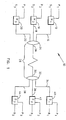
- Fig. 1 is a schematic diagram illustrating the system 10 of this invention for transmitting a plurality (I) of independent optical signals ⁇ S i ⁇ through a single optical channel.
- Three independent optical signals S 1 , S 2 and S 3, each of which may be amplitude-modulated and of identical frequency and phase, for example, are shown coupled to separate mode modulators, which may include, for example, electro-optical polarizers.
- the three mutually orthogonal PRN sequences P 1 , P 2 and P 3 each have a white or Gaussian spectral density function and may include a Gold code, Walsh code, or any other suitable digital sequence having the necessary orthogonality and white spectral characteristics.
- the mode modulator 12 accepts a PRN sequence P 1 and varies the polarization mode of signal S 1 to produce the modulated optical signal 14.
- the mode modulator 16 accepts a PRN sequence P 2 and varies the polarization mode of signal S 2 to produce the modulated optical signal 18
- the mode modulator 20 accepts a PRN sequence P 3 and varies the polarization mode of signal S 3 to produce the modulated optical signal 22.
- This example includes only three signals but may be scaled to larger numbers of signals.
- Modulated optical signals 14, 18, and 22 are accepted at the optical combiner 24 wherein they are combined to from a single optical multiplex signal that is coupled to one end 26 of the optical channel 28.
- the other end 30 of optical, channel 28 is coupled to an optical splitter 32, which splits the single optical multiplex signal into the three optical multiplex signal copies 34, 36 and 38.
- Optical multiplex signal 34 is coupled to the mode demodulator 40, which may include, for example, an electro-optical polarizer and a polarization filter.
- optical multiplex signal 36 is coupled to the mode demodulator 42 and optical multiplex signal 38 is coupled to the mode demodulator 44.
- mode modulators 40, 42 and 44 are very similar and may be appreciated from the description of mode modulator 40.
- PRN sequences P 1 , P 2 and P 3 are reproduced at the receiving end 30 of optical channel 28 by any useful method known in the art.
- a second PRN generator may be employed with the same algorithms and seed values to produce the PRN sequences P 1 , P 2 and P 3 in synchronization with the PRN generator employed to produce the PRN sequences P 1 , P 2 and P 3 used at the end 26 of optical channel 28.
- synchronization data bits may be transferred as an additional signal S 4 (not shown) through optical channel 28.
- PRN sequence P 1 is coupled to mode demodulator 40, which modulates the polarization mode of optical multiplex signal 34 accordingly to produce an intermediate modulated multiplex signal MMS 1 (not shown).
- one of the optical signals may be used as a PMD pilot signal S P to obtain a correction for channel PMD by introducing a variable delay between the quadrature components of the pilot signal S P and varying the delay as necessary to properly recover the pilot signal S P .
- a single-mode fiber from a splitter can be rotated physically to orthogonalize the signal polarization between the splitter outputs and the components then combined and transmitted as a pilot signal S P with a known relative polarization.
- Figs. 2A-B are schematic diagrams illustrating the system of this invention for transmitting a PMD pilot signal S P through a single optical channel.
- Fig. 2A shows the transmit end apparatus 46 and
- Fig. 2B shows the receive end apparatus 48 for the PMD pilot signal S P .
- a laser 50 creates an optical signal 52, which is passed though a half-wave plate 54 to fix its polarization mode and a beam-splitter 54 to generate two identical optical signals 56 and 58 having a known state of polarization (SOP).
- a pilot signal bit sequence 60 is applied to the two identical mode modulators 62 and 64 to create two identical modulated pilot signals 66 and 68, which are coupled via polarization-maintaining fibers to the respective arms of the polarization combiner 70.
- Each arm of polarization combiner 70 properly couples only through one SOP, which is acquired by appropriately rotating the polarization-maintaining optical fibers carrying signals 66 and 68 with respect to the respective fibers in polarization-combiner 70.
- polarization combiner 70 adds two orthogonally-polarized pilot signals 66 and 68 to produce a dual-SOP pilot signal 72, which is transmitted through the optical channel 74.
- dual-SOP pilot signal 72 arrives at the 2-by-2 optical coupler 76.
- the laser 78 generates an optical signal for heterodyne recovery of the pilot signals in the usual manner.
- the output of laser 78 is rotated by the quarter-wave plate 80 and the half-wave plate 82 to select either one of the two SOPs in dual-SOP pilot signal 72.
- One of the optical outputs 84 and 86 from 2-by-2 optical coupler 76 is passed through a variable length path 88 to introduce a relative delay that represents the PMD in the channel.
- the signal processor 90 which may include optical detectors, a mixer and a phase-lock loop, to recover the original pilot signal bit sequence 60.
- Processor 90 provided an automatic frequency control (AFC) signal 92 and a PMD compensation signal 94, which may be used to correct for the slowly varying mode distortion in channel 74.
- AFC automatic frequency control
- Fig. 3 is a block diagram illustrating an exemplary embodiment of the apparatus 96 of this invention for transmitting a plurality (I) of independent optical signals ⁇ S i ⁇ through a single optical channel 98, which may include free space or an optical waveguide or the like.
- a pseudorandom bit sequence (PRBS) generator 100 provides a set of code sequences ⁇ P i ⁇ that have the mutually orthogonal and white spectral properties known in the signal processing arts for code division multiplexing.
- PRBS pseudorandom bit sequence
- a plurality of electro-optical modulators exemplified by the electro-optical modulator 102 are each disposed to accept one signal S i of a plurality of independent optical signals ⁇ S i ), which may be, for example, an amplitude-modulated laser output signal carrying data that is to be transmitted through optical channel 98.
- Electro-optical modulator 102 accepts the optical signal S 1 and modulates the polarization mode of S 1 according to the PRBS P 1 to produce the modulated optical signal MS 1 .
- the other electro-optical modulators operate similarly and together produce the plurality of modulated optical signals ⁇ MS i ⁇ , which are coupled to the optical combiner 104.
- Optical combiner 104 merely adds the plurality of modulated optical signals ⁇ MS i ⁇ to form a single optical multiplex signal 106, which is coupled to the optical channel input 108.
- an optical multiplex signal 110 representing a version of optical multiplex signal 106 with some degree of additional noise and distortion, is coupled by way of the optical channel output 112 to an optical splitter 114, which creates a plurality of identical copies of optical multiplex signals 110.
- a second PRBS generator 118 provides the set of code sequences ⁇ P i ⁇ and is synchronized with PRBS generator 100 by any useful means known in the art, such as a synchronous clock recovery scheme or an additional PRBS correlator 120 disposed to ensure accurate duplication and synchrony of the PRBSs 100 and 118 at each end of optical channel 98.
- Electro-optical modulator 116 accepts optical multiplex signal 110 and modulates the polarization mode thereof according to P 1 to produce the modulated multiplex signal MMS 1 in which all of the energy correlated with P 1 is now propagating in a single SOP.
- Modulated multiplex signal MMS 1 is then filtered by a polarized mode filter 122 to remove all signal energy except the energy having the SOP for which mode filter 122 is tuned. Because of the fixed SOP, mode filter 122 passes only the energy in MMS 1 that is correlated to P 1 . This includes only the original S 1 because all other energy is uncorrelated by virtue of the orthogonality of the set of PRBSs ⁇ P i ⁇ .
- the other electro-optical modulators operate similarly and together produce the plurality of modulated multiplex signals ⁇ MMS i ⁇ , each of which is then filtered by a mode filter tuned to a single SOP, thereby recovering the plurality (I) of independent optical signals ⁇ S i ⁇ .
- the SOP of the mode filters exemplified by mode filter 122, may be dynamically adjusted to compensate for PMD in optical channel 98 by some means such described above in connection with Figs. 2A-2B.
- Fig. 4 is a schematic diagram of a flowchart illustrating the method ofthis invention for transmitting a plurality (I) of independent optical signals ⁇ S i ⁇ through a single optical channel.
- the plurality (I) of PRBSs ⁇ P i ⁇ is generated and, in step 126, the plurality (I) of independent optical signals ⁇ S i ⁇ is produced.
- the plurality (I) of modulated optical signals ⁇ MS i ⁇ is combined into an optical multiplex signal, which is transmitted through the optical channel from one end to the other in the step 132.
- the preselected optical mode of the received optical multiplex signal is modulated with the i th PRBS P i to form an i th modulated multiplex signal MMS i .
- the i th modulated multiplex signal MMS i is filtered with a mode filter to remove uncorrelated energy and recover the independent optical signal S i .
- i ⁇ 1, . . . I ⁇ if appropriate.
Landscapes
- Physics & Mathematics (AREA)
- Electromagnetism (AREA)
- Engineering & Computer Science (AREA)
- Computer Networks & Wireless Communication (AREA)
- Signal Processing (AREA)
- Optical Communication System (AREA)
Abstract
Description
Claims (8)
- A method for transferring a plurality (I) of independent optical signals {Si} through an optical channel (98) having two ends (108, 112), the method comprising the steps of:(a) generating a plurality (I) of independent pseudorandom bit sequences (PRBSs);(b) modulating a preselected optical mode of the ith independent optical signal Si according to the ith independent pseudorandom bit sequence PRBSi to form an ith modulated optical signal MSi, where I = { 1,. I};(c) combining a plurality (I) of the modulated optical signals {MSi} to form an optical multiplex signal (106);(d) transmitting the optical multiplex signal (106, 110) through the optical channel (98) from one end (108) to the other end (112);(e) modulating the preselected optical mode of the optical multiplex signal (110) according to the ith pseudorandom bit sequence PRBSi to form an ith modulated multiplex signal MMSi, and(f) passing the ith modulated multiplex signal MMSi through a mode filter (122), whereby the independent optical signal Si is recovered.
- The method of claim 1 wherein the preselected optical mode comprises an optical polarization mode.
- The method of claim 1 or 2 wherein the optical channel (98) comprises an optical waveguide.
- The method of claim 3 wherein the optical channel (98) comprises a fiber optical channel.
- The method of claim 1 or 2 wherein the optical channel (98) comprises free space.
- The method of claim 5 wherein the plurality (I) of independent PRBSs are mutually orthogonal.
- The method of one of the preceding claims wherein the plurality (I) of independent PRBSs are mutually orthogonal.
- An apparatus (96) for transferring a plurality (I) of independent optical signals {Si} through an optical channel (98) having two ends (108, 112), the apparatus comprising:a first pseudorandom bit sequence (PRBS) generator (100) for generating a plurality (I) of independent PRBSs;a plurality (I) of electro-optical modulators (102) each coupled to the PRBS generator (100) and disposed for modulating the polarization mode of the ith optical signal Si according to the ith pseudorandom bit sequence PRBSi to form a modulated optical signal MSi, where I= {1, . . . I};an optical combiner (104) disposed at one end (108) of the optical channel (98) for combining a plurality (I) of the modulated optical signals {MSi} to form an optical multiplex signal (106, 110) for transmission through the optical channel (98);at least one electro-optical modulator (116) coupled to the PRBS generator (100) and disposed at the other end (112) of the optical channel (98) for modulating the polarization mode ofthe optical multiplex signal (106, 110) according to the ith pseudorandom bit sequence PRBS, to form an ith modulated multiplex signal MMSi; anda polarized filter (122) disposed at the other end (112) of the optical channel (98) for filtering the ith modulated multiplex signal MMSi, whereby the independent optical signal Si is recovered.
Applications Claiming Priority (2)
| Application Number | Priority Date | Filing Date | Title |
|---|---|---|---|
| US87386 | 1993-07-02 | ||
| US10/087,386 US7280764B2 (en) | 2002-03-01 | 2002-03-01 | Optical signal multiplexer/demultiplexer employing pseudorandom mode modulation |
Publications (3)
| Publication Number | Publication Date |
|---|---|
| EP1341323A2 true EP1341323A2 (en) | 2003-09-03 |
| EP1341323A3 EP1341323A3 (en) | 2005-09-28 |
| EP1341323B1 EP1341323B1 (en) | 2009-02-11 |
Family
ID=27733427
Family Applications (1)
| Application Number | Title | Priority Date | Filing Date |
|---|---|---|---|
| EP02023243A Expired - Lifetime EP1341323B1 (en) | 2002-03-01 | 2002-10-16 | Optical signal multiplexer/demultiplexer employing pseudorandom mode modulation |
Country Status (4)
| Country | Link |
|---|---|
| US (1) | US7280764B2 (en) |
| EP (1) | EP1341323B1 (en) |
| JP (1) | JP2003273807A (en) |
| DE (1) | DE60231104D1 (en) |
Cited By (1)
| Publication number | Priority date | Publication date | Assignee | Title |
|---|---|---|---|---|
| EP2779127A3 (en) * | 2013-03-14 | 2018-02-28 | Kidde Technologies, Inc. | Pneumatic sensing apparatus for fire or overheat alarm |
Families Citing this family (13)
| Publication number | Priority date | Publication date | Assignee | Title |
|---|---|---|---|---|
| US7580524B2 (en) * | 2002-03-11 | 2009-08-25 | Universite De Geneve | Method and apparatus for synchronizing the emitter and the receiver in an autocompensating quantum cryptography system |
| US7519295B2 (en) * | 2003-10-30 | 2009-04-14 | Tyco Telecommunications (Us) Inc. | Apparatus and method for commissioning an optical transmission system |
| AU2006208719B2 (en) * | 2005-01-26 | 2009-05-28 | Xieon Networks S.A.R.L. | Method for optically transmitting polarisation multiplex signals |
| US7706536B2 (en) * | 2005-05-17 | 2010-04-27 | Alcatel-Lucent Usa Inc. | Phase locking in a multi-channel quantum communication system |
| US20060263096A1 (en) * | 2005-05-17 | 2006-11-23 | Mihaela Dinu | Multi-channel transmission of quantum information |
| US7558486B2 (en) * | 2005-09-28 | 2009-07-07 | Alcatel-Lucent Usa Inc. | All-optical methods and systems |
| JP4872377B2 (en) * | 2006-02-22 | 2012-02-08 | 沖電気工業株式会社 | Ranging method for communication system between central station and multiple terminals |
| JP5130702B2 (en) * | 2006-12-05 | 2013-01-30 | 富士通株式会社 | Polarization orthogonal controller |
| US20090214224A1 (en) * | 2007-04-03 | 2009-08-27 | Celight, Inc. | Method and apparatus for coherent analog rf photonic transmission |
| JP5141498B2 (en) * | 2008-10-30 | 2013-02-13 | 富士通株式会社 | Optical transmission / reception system, optical transmitter, optical receiver, and optical transmission / reception method |
| US20100150555A1 (en) * | 2008-12-12 | 2010-06-17 | Zinan Wang | Automatic polarization demultiplexing for polarization division multiplexed signals |
| US9374188B2 (en) * | 2008-12-12 | 2016-06-21 | Alcatel Lucent | Optical communication using polarized transmit signal |
| FR3037456B1 (en) * | 2015-06-10 | 2017-06-02 | Thales Sa | METHOD FOR SYNTHESIZING AN ANALOGUE NOISE, NOISE SYNTHESIZER AND ENCODING CHAIN USING SUCH A SYNTHESIZER |
Family Cites Families (8)
| Publication number | Priority date | Publication date | Assignee | Title |
|---|---|---|---|---|
| US3956626A (en) | 1973-06-14 | 1976-05-11 | Mcdonnell Douglas Corporation | Pulse quaternary communication means |
| FI97505C (en) * | 1994-11-29 | 1996-12-27 | Nokia Telecommunications Oy | Procedure for data communication, transmitters and receivers |
| NL1005263C2 (en) | 1996-03-06 | 1997-09-09 | Nederland Ptt | Optical packet-switched transmission network. |
| US5959750A (en) * | 1996-06-06 | 1999-09-28 | Lucent Technologies Inc. | Method of upgrading transmission capacity by Raman amplification |
| US6188768B1 (en) | 1998-03-31 | 2001-02-13 | International Business Machines Corporation | Autocompensating quantum cryptographic key distribution system based on polarization splitting of light |
| US6674557B1 (en) * | 1998-09-21 | 2004-01-06 | Corning Incorporated | Wavelength division multiplexing systems |
| US6137925A (en) | 1998-11-24 | 2000-10-24 | Agilent Technologies Inc. | Multi-wavelength polarization scrambling device |
| US6714742B1 (en) * | 1999-05-20 | 2004-03-30 | University Of Southern California | Polarization-division multiplexing based on power encoding of different polarization channels |
-
2002
- 2002-03-01 US US10/087,386 patent/US7280764B2/en not_active Expired - Fee Related
- 2002-10-16 DE DE60231104T patent/DE60231104D1/en not_active Expired - Fee Related
- 2002-10-16 EP EP02023243A patent/EP1341323B1/en not_active Expired - Lifetime
-
2003
- 2003-02-26 JP JP2003049178A patent/JP2003273807A/en not_active Withdrawn
Cited By (1)
| Publication number | Priority date | Publication date | Assignee | Title |
|---|---|---|---|---|
| EP2779127A3 (en) * | 2013-03-14 | 2018-02-28 | Kidde Technologies, Inc. | Pneumatic sensing apparatus for fire or overheat alarm |
Also Published As
| Publication number | Publication date |
|---|---|
| US20040208634A1 (en) | 2004-10-21 |
| EP1341323B1 (en) | 2009-02-11 |
| DE60231104D1 (en) | 2009-03-26 |
| EP1341323A3 (en) | 2005-09-28 |
| US7280764B2 (en) | 2007-10-09 |
| JP2003273807A (en) | 2003-09-26 |
Similar Documents
| Publication | Publication Date | Title |
|---|---|---|
| US7167651B2 (en) | System and method for code division multiplexed optical communication | |
| US8014686B2 (en) | Polarization demultiplexing optical receiver using polarization oversampling and electronic polarization tracking | |
| US8050564B2 (en) | Coherent optical channel substitution | |
| US8406638B2 (en) | Coherent light receiving system | |
| US8805200B2 (en) | Optical transmission system | |
| US7224906B2 (en) | Method and system for mitigating nonlinear transmission impairments in fiber-optic communications systems | |
| JP3829198B2 (en) | Optical transmission method and system | |
| US6714742B1 (en) | Polarization-division multiplexing based on power encoding of different polarization channels | |
| Hayee et al. | Doubling of bandwidth utilization using two orthogonal polarizations and power unbalancing in a polarization-division-multiplexing scheme | |
| US7280764B2 (en) | Optical signal multiplexer/demultiplexer employing pseudorandom mode modulation | |
| US20060045527A1 (en) | Multiplexing communication system and crosstalk elimination method | |
| US20030090768A1 (en) | Long haul optical communication system | |
| CN102932089A (en) | Multi-carrier code division multiplexing light transmission system and method based on ultra dense wavelength division multiplexing | |
| EP1329047A1 (en) | System and method for code division multiplexed optical communication | |
| JP3625726B2 (en) | Optical transmission device and optical transmission system | |
| Srivastava et al. | A polarization multiplexing technique to mitigate WDM crosstalk in SOAs | |
| Aboagye et al. | Performance analysis of 112 Gb/s× 4-channel WDM PDM-DQPSK optical label switching system with spectral amplitude code labels | |
| JP7659363B2 (en) | Optical transmitter, optical access system, and optical transmission method | |
| Renaudier et al. | Long-haul WDM transmission of 448 Gbit/s polarisation-division multiplexed 16-ary quadrature amplitude modulation using coherent detection | |
| WO2003028267A1 (en) | Mitigating nonlinear transmission impairments in fiber-optic communications systems | |
| Kato et al. | Coherent-optical in-line add/drop of PDM tributaries of subcarrier multiplexed signals | |
| WO2000072492A1 (en) | Polarization-division multiplexing based on power encoding of different polarization channels | |
| Hinz et al. | Polarization Multiplexed 2× 20Gbit/s RZ Transmission using Interference Detection | |
| Hu et al. | Coherent-Lite with Low-Complexity Baud-Rate-Sampling Receiver Enabled by Clock and Wavelength Locking Over 80 Km 7-Core Fiber | |
| Izquierdo et al. | Roadmap to Simplified Coherent Heterodyne Receivers for 100 Gb/s PONs |
Legal Events
| Date | Code | Title | Description |
|---|---|---|---|
| PUAI | Public reference made under article 153(3) epc to a published international application that has entered the european phase |
Free format text: ORIGINAL CODE: 0009012 |
|
| AK | Designated contracting states |
Kind code of ref document: A2 Designated state(s): AT BE BG CH CY CZ DE DK EE ES FI FR GB GR IE IT LI LU MC NL PT SE SK TR |
|
| AX | Request for extension of the european patent |
Extension state: AL LT LV MK RO SI |
|
| PUAL | Search report despatched |
Free format text: ORIGINAL CODE: 0009013 |
|
| AK | Designated contracting states |
Kind code of ref document: A3 Designated state(s): AT BE BG CH CY CZ DE DK EE ES FI FR GB GR IE IT LI LU MC NL PT SE SK TR |
|
| AX | Request for extension of the european patent |
Extension state: AL LT LV MK RO SI |
|
| 17P | Request for examination filed |
Effective date: 20060301 |
|
| AKX | Designation fees paid |
Designated state(s): DE FR GB |
|
| 17Q | First examination report despatched |
Effective date: 20060824 |
|
| RAP1 | Party data changed (applicant data changed or rights of an application transferred) |
Owner name: AVAGO TECHNOLOGIES FIBER IP (SINGAPORE) PTE. LTD. |
|
| GRAP | Despatch of communication of intention to grant a patent |
Free format text: ORIGINAL CODE: EPIDOSNIGR1 |
|
| GRAS | Grant fee paid |
Free format text: ORIGINAL CODE: EPIDOSNIGR3 |
|
| GRAA | (expected) grant |
Free format text: ORIGINAL CODE: 0009210 |
|
| AK | Designated contracting states |
Kind code of ref document: B1 Designated state(s): DE FR GB |
|
| REG | Reference to a national code |
Ref country code: GB Ref legal event code: FG4D |
|
| REF | Corresponds to: |
Ref document number: 60231104 Country of ref document: DE Date of ref document: 20090326 Kind code of ref document: P |
|
| PLBE | No opposition filed within time limit |
Free format text: ORIGINAL CODE: 0009261 |
|
| STAA | Information on the status of an ep patent application or granted ep patent |
Free format text: STATUS: NO OPPOSITION FILED WITHIN TIME LIMIT |
|
| 26N | No opposition filed |
Effective date: 20091112 |
|
| REG | Reference to a national code |
Ref country code: FR Ref legal event code: ST Effective date: 20100630 |
|
| PG25 | Lapsed in a contracting state [announced via postgrant information from national office to epo] |
Ref country code: DE Free format text: LAPSE BECAUSE OF NON-PAYMENT OF DUE FEES Effective date: 20100501 Ref country code: FR Free format text: LAPSE BECAUSE OF NON-PAYMENT OF DUE FEES Effective date: 20091102 |
|
| PGFP | Annual fee paid to national office [announced via postgrant information from national office to epo] |
Ref country code: GB Payment date: 20121010 Year of fee payment: 11 |
|
| REG | Reference to a national code |
Ref country code: GB Ref legal event code: 732E Free format text: REGISTERED BETWEEN 20130725 AND 20130731 |
|
| GBPC | Gb: european patent ceased through non-payment of renewal fee |
Effective date: 20131016 |
|
| PG25 | Lapsed in a contracting state [announced via postgrant information from national office to epo] |
Ref country code: GB Free format text: LAPSE BECAUSE OF NON-PAYMENT OF DUE FEES Effective date: 20131016 |