EP1341320A1 - Mobile communication device - Google Patents
Mobile communication device Download PDFInfo
- Publication number
- EP1341320A1 EP1341320A1 EP01998167A EP01998167A EP1341320A1 EP 1341320 A1 EP1341320 A1 EP 1341320A1 EP 01998167 A EP01998167 A EP 01998167A EP 01998167 A EP01998167 A EP 01998167A EP 1341320 A1 EP1341320 A1 EP 1341320A1
- Authority
- EP
- European Patent Office
- Prior art keywords
- mobile unit
- electric power
- transmitted electric
- communication apparatus
- predicted distance
- Prior art date
- Legal status (The legal status is an assumption and is not a legal conclusion. Google has not performed a legal analysis and makes no representation as to the accuracy of the status listed.)
- Ceased
Links
- 238000010295 mobile communication Methods 0.000 title description 5
- 230000003044 adaptive effect Effects 0.000 claims abstract description 16
- 238000004891 communication Methods 0.000 claims description 80
- 230000010363 phase shift Effects 0.000 claims description 6
- 230000003287 optical effect Effects 0.000 abstract 1
- 238000000034 method Methods 0.000 description 12
- 230000015654 memory Effects 0.000 description 10
- 238000010586 diagram Methods 0.000 description 8
- 230000001133 acceleration Effects 0.000 description 2
- 230000000694 effects Effects 0.000 description 2
- 238000005259 measurement Methods 0.000 description 2
- 238000005516 engineering process Methods 0.000 description 1
- 239000011159 matrix material Substances 0.000 description 1
Images

Classifications
-
- H—ELECTRICITY
- H04—ELECTRIC COMMUNICATION TECHNIQUE
- H04B—TRANSMISSION
- H04B7/00—Radio transmission systems, i.e. using radiation field
- H04B7/24—Radio transmission systems, i.e. using radiation field for communication between two or more posts
- H04B7/26—Radio transmission systems, i.e. using radiation field for communication between two or more posts at least one of which is mobile
-
- H—ELECTRICITY
- H04—ELECTRIC COMMUNICATION TECHNIQUE
- H04B—TRANSMISSION
- H04B7/00—Radio transmission systems, i.e. using radiation field
- H04B7/02—Diversity systems; Multi-antenna system, i.e. transmission or reception using multiple antennas
- H04B7/04—Diversity systems; Multi-antenna system, i.e. transmission or reception using multiple antennas using two or more spaced independent antennas
- H04B7/08—Diversity systems; Multi-antenna system, i.e. transmission or reception using multiple antennas using two or more spaced independent antennas at the receiving station
- H04B7/0837—Diversity systems; Multi-antenna system, i.e. transmission or reception using multiple antennas using two or more spaced independent antennas at the receiving station using pre-detection combining
- H04B7/0842—Weighted combining
- H04B7/086—Weighted combining using weights depending on external parameters, e.g. direction of arrival [DOA], predetermined weights or beamforming
-
- H—ELECTRICITY
- H01—ELECTRIC ELEMENTS
- H01Q—ANTENNAS, i.e. RADIO AERIALS
- H01Q3/00—Arrangements for changing or varying the orientation or the shape of the directional pattern of the waves radiated from an antenna or antenna system
- H01Q3/26—Arrangements for changing or varying the orientation or the shape of the directional pattern of the waves radiated from an antenna or antenna system varying the relative phase or relative amplitude of energisation between two or more active radiating elements; varying the distribution of energy across a radiating aperture
- H01Q3/2605—Array of radiating elements provided with a feedback control over the element weights, e.g. adaptive arrays
-
- H—ELECTRICITY
- H04—ELECTRIC COMMUNICATION TECHNIQUE
- H04B—TRANSMISSION
- H04B7/00—Radio transmission systems, i.e. using radiation field
- H04B7/02—Diversity systems; Multi-antenna system, i.e. transmission or reception using multiple antennas
- H04B7/04—Diversity systems; Multi-antenna system, i.e. transmission or reception using multiple antennas using two or more spaced independent antennas
- H04B7/0408—Diversity systems; Multi-antenna system, i.e. transmission or reception using multiple antennas using two or more spaced independent antennas using two or more beams, i.e. beam diversity
-
- H—ELECTRICITY
- H04—ELECTRIC COMMUNICATION TECHNIQUE
- H04B—TRANSMISSION
- H04B7/00—Radio transmission systems, i.e. using radiation field
- H04B7/02—Diversity systems; Multi-antenna system, i.e. transmission or reception using multiple antennas
- H04B7/04—Diversity systems; Multi-antenna system, i.e. transmission or reception using multiple antennas using two or more spaced independent antennas
- H04B7/06—Diversity systems; Multi-antenna system, i.e. transmission or reception using multiple antennas using two or more spaced independent antennas at the transmitting station
- H04B7/0613—Diversity systems; Multi-antenna system, i.e. transmission or reception using multiple antennas using two or more spaced independent antennas at the transmitting station using simultaneous transmission
- H04B7/0615—Diversity systems; Multi-antenna system, i.e. transmission or reception using multiple antennas using two or more spaced independent antennas at the transmitting station using simultaneous transmission of weighted versions of same signal
- H04B7/0617—Diversity systems; Multi-antenna system, i.e. transmission or reception using multiple antennas using two or more spaced independent antennas at the transmitting station using simultaneous transmission of weighted versions of same signal for beam forming
Definitions
- the present invention relates to a mobile unit communication apparatus and more particularly to a mobile unit communication apparatus capable of providing excellent communication quality in mobile communications which encounter intermittent communication sessions from mobile units, such as packet communications.
- radio access system having radio cells (or cells) with which a bas station can communicate in an area defined around the base station, the radio access system accommodating a plurality of mobile terminals.
- the overall communication capacity of the radio access system is increased by using different frequencies and spreading codes between adjacent cells for reusing frequencies.
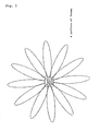
- Fig. 1 of the accompanying drawings shows a pattern of beams radiated from a base station in an antenna device of the radio communication system disclosed in the above publication. As shown in Fig. 1, predetermined angularly narrow beams are generated in desired directions under directivity control to cover all bearings.
- the radio communication system disclosed in the above publication inspects a change in the intensity of received electric power which occurs as a communicating mobile unit (also referred to as "terminal station” in the present specification) moves and adapts itself to the movement of the mobile unit under directivity control.
- Japanese laid-open patent publication No. 2000-22618 discloses a base station in a radio access system which changes the direction of an antenna and a beam angle based on the positional information of mobile terminals to minimize interferences between radio links to increase t he number of mobile terminals that can be accommodated by cells of the base station. While the systems disclosed in Japanese laid-open patent publications Nos. 7-87011 and 2000-22618 predict positions and control beam directions and beam widths, they select beams of predetermined beam characteristics, and do not adaptively control beam characteristics to form nulls in the directions of given interference signals by adapting themselves to radio wave environments.
- a mobile unit communication apparatus comprising an adaptive antenna having a plurality of antenna elements, for controlling the weighting on the antenna elements thereby to radiate beams that are adapted to radio wave environments, a position estimator for estimating the position of a mobile unit, a beam combiner for weighting signals received from the mobile unit by the antenna elements and combining beams, and a weighting coefficient generator for correcting weighting coefficients adapted to radio wave environments, which give initial weights as weights to form nulls in bearings other than the mobile unit based on the position of the mobile unit which has been estimated by the position estimator, for thereby reducing a time required for convergence.
- initial weights are given as weights to form nulls in bearings other than the mobile unit, and weighting coefficients adapted to radio wave environments are corrected. Even when intermittent communication sessions are being made from a mobile unit such as in packet communications, it is possible to achieve excellent communication quality by orienting the beam directivity of the adaptive antenna to a terminal station with which to communicate, and forming nulls for other mobile units acting as interference sources.
- the position estimator has a speed estimator for being supplied with the signals which have been received from the mobile unit by the antenna elements, and estimating the speed of the mobile unit based on a phase shift from a reference value of a predetermined pilot signal component.
- the speed of the mobile unit can be estimated, even when the mobile unit is making intermittent communication sessions, it is possible to perform an adaptive beam control process depending on the position of the terminal station for maximizing a signal-to-noise/interference ratio for a terminal station which is being handled and minimizing interferences for other terminal stations.
- the position estimator has a speed estimator for estimating the speed of the mobile unit based on a change in a pilot signal outputted from the beam combiner.
- the speed of the mobile unit can be estimated, even when the mobile unit is making intermittent communication sessions, it is possible to perform an adaptive beam control process depending on the position of the terminal station for maximizing a signal-to-noise/interference ratio for a terminal station which is being handled and minimizing interferences for other terminal stations.
- the mobile unit communication apparatus according to any one of the first through third inventions further comprises a weight corrector for correcting the weights with estimated values of the speed at which the mobile unit moves and the direction in which the mobile unit moves.
- a mobile unit communication system comprising a mobile unit communication apparatus according to any one of the first through fourth inventions wherein the position estimator has a distance predictor, a transmitted electric power controller for controlling transmitted electric power depending on a predicted distance, and a transmitted electric power controller mounted on a mobile unit for transmitting a predicted distance to the mobile unit and controlling transmitted electric power of the mobile unit depending on the predicted distance.
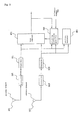
- Fig. 2 is a diagram showing an arrangement of a mobile unit communication apparatus according to the present invention and operation thereof.
- the mobile unit communication apparatus according to the present invention comprises an adaptive antenna having a plurality of antenna elements 101 through 10N, for controlling the weighting on antenna elements 101 through 10N thereby to radiate beams that are adapted to radio wave environments, position estimator 601 for estimating the position of a mobile unit, beam combiner 401 for weighting signals received from the mobile unit by antenna elements 101 through 10N and combining beams, and weighting coefficient generator 501 for correcting weighting coefficients adapted to radio wave environments, which give initial weights as weights to form nulls in bearings other than the mobile unit based on the position of the mobile unit which has been estimated by position estimator 601.
- the mobile unit communication apparatus shown in Fig. 2 also has transceivers 201 through 20N for converting signals received from a mobile unit into signals having predetermined frequencies and despreaders 301 through 30N for demodulating the received signals which have been converted into the signals having predetermined frequencies.
- the signals received by antenna elements 101 through 10N are supplied via respective transceivers 201 through 20N to respective despreaders 301 through 30N.
- the received signals which have been demodulated by respective despreaders 301 through 30N are then supplied to beam combiner 401, weighting coefficient generator 501, and position estimator 601.
- Beam combiner 401 weights the signals which have been received by respective antenna elements 101 through 10N and demodulated by respective despreaders 301 through 30N according to the weighting coefficients outputted from coefficient generator 501, and combines the weighted signals into a desired received adaptive beam pattern.
- Weighting coefficient generator 501 is supplied with the received signals which have been demodulated by respective despreaders 301 through 30N, the beam outputted from beam combiner 401, reference signal 701, and the estimated position outputted from position estimator 601, calculates an error signal representing an error between reference signal 701 and the beam outputted from beam combiner 401, and multiplies the error signal by the received signals which have been demodulated by respective despreaders 301 through 30N thereby to calculate weighting coefficients.
- Weighting coefficient generator 501 further multiplies the weighting coefficients by a corrective coefficient depending on the estimated position for thereby generating weighting coefficients to be outputted to beam combiner 401 which have been adapted to radio wave environments, which give initial weights as weights to form nulls in bearings other than the mobile unit.
- the weighting coefficients thus generated serve to reduce the time required for convergence.
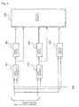
- FIG. 3 shows an arrangement and operation of an embodiment of position estimator 601.
- position estimator 601 comprises speed estimators 611 through 61N for being supplied with the received signals which have been demodulated by respective despreaders 301 through 30N and estimating the present speed of a terminal station, speed memories 621 through 62N for being supplied with estimated speeds inputted from speed estimators 611 through 61N and storing past speeds of the terminal station, bearing memory 630 for being supplied with the received signals which have been demodulated by respective despreaders 301 through 30N, calculating the bearing of the terminal station, and storing the present and past bearings of the terminal station, and position predictor 640 for being supplied with signals outputted from speed estimators 611 through 61N, speed memories 621 through 62N, and bearing memory 630.
- position estimator 601 Since position estimator 601 has speed estimators 611 through 61N, it can estimate the speed at which the mobile unit moves. Therefore, even when the mobile unit is making intermittent communication sessions, it is possible to perform an adaptive beam control process depending on the position of the terminal station for maximizing a signal-to-noise/interference ratio for a terminal station which is being handled and minimizing interferences for other terminal stations.
- Speed estimators 611 through 61N are supplied with the received signals from corresponding despreaders 301 through 30N, and calculate the speed of the terminal station based on a phase shift of pilot signal 660 from a reference value.
- the signals outputted from signal estimators 611 through 61N are supplied corresponding speed memories 621 through 62N and position predictor 640.
- Bearing memory 630 calculates the bearing in which the received signals arrive based on an inherent value produced by a correlating process between the signals which have been received by antenna elements 101 through 101N and demodulated by despreaders 301 through 30N.
- Position predictor 640 is supplied with signals outputted from speed estimators 611 through 61N, speed memories 621 through 62N, and bearing memory 630, and estimates a future position to which the terminal station will move based on a change in the speed and a change in the bearing.
- the signals received by antenna elements 101 through 101N include an added phase shift due to the Doppler effect. It is possible to estimate the speed of the terminal station by extracting the Doppler quantity.
- phase of bits of the pilot signal at time t(0) is represented by ⁇ (0)
- the phase of bits of the pilot signal at time t(1) by ⁇ (1), and so on and a phase shift ⁇ between two times is calculated.
- ⁇ t is selected depending on the speed of the terminal station that is assumed. For example, if the mobile unit communication apparatus employs the CDMA system, then ⁇ t is selected from one chip, one slot, or one frame of the shortest code modulation. One type may be selected or different types may be switched depending on a change in the speed of the mobile unit.
- the estimated speeds calculated by speed estimators 611 through 61N for the respective received signals from antenna elements 101 through 10N are then averaged by position predictor 640.
- the estimated speeds may be averaged as a simple added mean value or a weighted mean value weighted by the intensities of the signals received by the antenna elements.
- Bearing memory 630 calculates the bearing in which the received signals arrive based on a correlating process (an analysis of an inherent value of a correlation matrix, so-called a MUSIC process) between the signals which have been received by antenna elements 101 through 101N, and stores the calculated bearing.
- the calculated bearing and chronological data of stored bearings are supplied to position predictor 640.
- Position predictor 640 calculates an acceleration based on a change in the estimated speed within a predetermined time ( ⁇ t) and a bearing in which the terminal station moves based on the positive or negative nature of the speed and the chronological data of bearings, and estimates the position to which the terminal station will move using the three parameters including the acceleration, the speed, and the moving bearing.
- the weighting coefficients for combining the beams which are presently generated are multiplied by a corrective coefficient (e.g., exp(- ⁇ d) where - ⁇ d represents the difference between the present and estimated bearings).
- weighting coefficients are calculated to give a restrictive condition such that the beam pattern which is being generated at present will have a new null in the estimated position to which the terminal station as an intensive interference source will move and will have directivity for the terminal station which is being handled.
- the motile communication device estimates the position to which a terminal station will move, even when intermittent communication sessions are being made from a mobile unit such as in packet communications, it is possible at all times to generate adaptive beams having a null in an interference bearing and having directivity for a terminal station which is being handled.
- the motile communication device may have a weight corrector for correcting weights using estimated values of the speed at which the mobile unit moves and the direction in which the mobile unit moves.
- the weight corrector makes it possible to carry out an adaptive control process capable of convergence within a short time even when the terminal station moves and also when the terminal station is making intermittent communication sessions such as packet communications.
- position estimator 601 has speed estimators 611 through 61N for estimating the speed at which the terminal station moves based on a change in the pilot signal that is outputted from beam combiner 401.
- the speed of the terminal station can be estimated, and even when intermittent communication sessions such as packet communications are being made, it is possible to perform an adaptive beam control process depending on the position of the terminal station for maximizing a signal-to-noise/interference ratio for a terminal station which is being handled and minimizing interferences for other terminal stations.
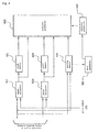
- Fig. 4 is a diagram showing an arrangement and operation of another position estimator for use in the mobile unit communication apparatus according to the present invention.
- the position estimator in the mobile unit communication apparatus shown in Fig. 4 differs from the position estimator shown in Fig. 3 in that it has distance predictor 650.
- Distance predictor 650 calculates an estimated distance from the base station based on a trigonometrical measurement process using the estimated bearing outputted from bearing memory 630 and estimated bearings calculated by another base station which are transmitted from a host apparatus 900 connected to a plurality of base stations.
- the estimated distance calculated by distance predictor 650 is outputted to position predictor 640 for positional prediction.
- the base station is capable of predicting the movement of the terminal station based on not only bearings, but also from distances, and hence is capable of predicting the position of the terminal station with better accuracy. Since the distance from the base station to the terminal station becomes clear, it is possible to control the transmitted electric power depending on the distance from the base station to the terminal station.
- Fig. 5 is a diagram showing an arrangement and operation of another mobile unit communication apparatus according to the present invention.
- the mobile unit communication apparatus shown in Fig. 5 differs from the mobile unit communication apparatus shown in Fig. 2 in that it has transmitted electric power controller 901.
- Transmitted electric power controller 901 is supplied with an estimated distance between the terminal station and the base station which is outputted from position estimator 601, and increases or reduces the electric power transmitted to the terminal station.
- Transmitted electric power controller 901 is also capable of controlling the electric power transmitted from the terminal station by sending transmitted electric power control information to the terminal station. Since the mobile unit communication apparatus can control the electric power transmitted from the base station and can also control the electric power transmitted from the terminal station, it is possible to perform communications with optimum electric power and reduce interferences with other terminal stations..
- the mobile unit communication apparatus capable of providing excellent communication quality by orienting the beam directivity of an adaptive antenna to a terminal station in mobile communications which encounter intermittent communication sessions from mobile units, such as packet communications.
Landscapes
- Engineering & Computer Science (AREA)
- Computer Networks & Wireless Communication (AREA)
- Signal Processing (AREA)
- Mobile Radio Communication Systems (AREA)
- Variable-Direction Aerials And Aerial Arrays (AREA)
- Radio Transmission System (AREA)
Abstract
An optical subscriber system according to the
present invention has an adaptive antenna having a plurality
of antenna elements, for controlling the weighting
on the antenna elements thereby to radiate beams that are
adapted to radio wave environments, a position estimator
for estimating the position of a mobile unit, a beam combiner
for weighting signals received from the mobile unit
by the antenna elements and combining beams, and a
weighting coefficient generator for correcting weighting
coefficients adapted to radio wave environments, which
give initial weights as weights to form nulls in bearings
other than the mobile unit based on the position of the
mobile unit which has been estimated by the position estimator,
for thereby reducing a time required for convergence.
Description
The present invention relates to a mobile unit
communication apparatus and more particularly to a mobile
unit communication apparatus capable of providing excellent
communication quality in mobile communications which
encounter intermittent communication sessions from mobile
units, such as packet communications.
According to the general mobile radio communication
technology, there has been realized a radio access
system having radio cells (or cells) with which a bas
station can communicate in an area defined around the
base station, the radio access system accommodating a
plurality of mobile terminals. The overall communication
capacity of the radio access system is increased by using
different frequencies and spreading codes between adjacent
cells for reusing frequencies.
One example of a radio communication system
which employs adaptive antennas in conventional mobile
communications is disclosed in Japanese laid-open patent
publication No. 7-87011. Fig. 1 of the accompanying
drawings shows a pattern of beams radiated from a base
station in an antenna device of the radio communication
system disclosed in the above publication. As shown in
Fig. 1, predetermined angularly narrow beams are generated
in desired directions under directivity control to
cover all bearings. The radio communication system disclosed
in the above publication inspects a change in the
intensity of received electric power which occurs as a
communicating mobile unit (also referred to as "terminal
station" in the present specification) moves and adapts
itself to the movement of the mobile unit under directivity
control.
Japanese laid-open patent publication No.
2000-22618 discloses a base station in a radio access
system which changes the direction of an antenna and a
beam angle based on the positional information of mobile
terminals to minimize interferences between radio links
to increase t he number of mobile terminals that can be
accommodated by cells of the base station. While the
systems disclosed in Japanese laid-open patent publications
Nos. 7-87011 and 2000-22618 predict positions and
control beam directions and beam widths, they select
beams of predetermined beam characteristics, and do not
adaptively control beam characteristics to form nulls in
the directions of given interference signals by adapting
themselves to radio wave environments.
It is an object of the present invention to
provide a mobile unit communication apparatus capable of
providing excellent communication quality by orienting
the beam directivity of an adaptive antenna to a mobile
unit in mobile communications which encounter intermittent
communication sessions from mobile units, such as
packet communications.
According to a first invention of the present
application which will solve the above problems, there is
provided a mobile unit communication apparatus comprising
an adaptive antenna having a plurality of antenna elements,
for controlling the weighting on the antenna elements
thereby to radiate beams that are adapted to radio
wave environments, a position estimator for estimating
the position of a mobile unit, a beam combiner for
weighting signals received from the mobile unit by the
antenna elements and combining beams, and a weighting coefficient
generator for correcting weighting coefficients
adapted to radio wave environments, which give initial
weights as weights to form nulls in bearings other than
the mobile unit based on the position of the mobile unit
which has been estimated by the position estimator, for
thereby reducing a time required for convergence.
With the above arrangement, based on the position
of the mobile unit which has been estimated by the
position estimator, initial weights are given as weights
to form nulls in bearings other than the mobile unit, and
weighting coefficients adapted to radio wave environments
are corrected. Even when intermittent communication sessions
are being made from a mobile unit such as in packet
communications, it is possible to achieve excellent communication
quality by orienting the beam directivity of
the adaptive antenna to a terminal station with which to
communicate, and forming nulls for other mobile units
acting as interference sources.
According to a second invention of the present
application, in the mobile unit communication apparatus
according to the first invention, the position estimator
has a speed estimator for being supplied with the signals
which have been received from the mobile unit by the antenna
elements, and estimating the speed of the mobile
unit based on a phase shift from a reference value of a
predetermined pilot signal component.
With the above arrangement, since the speed of
the mobile unit can be estimated, even when the mobile
unit is making intermittent communication sessions, it is
possible to perform an adaptive beam control process depending
on the position of the terminal station for maximizing
a signal-to-noise/interference ratio for a terminal
station which is being handled and minimizing interferences
for other terminal stations.
According to a third invention of the present
application, in the mobile unit communication apparatus
according to the first invention, the position estimator
has a speed estimator for estimating the speed of the mobile
unit based on a change in a pilot signal outputted
from the beam combiner.
With the above arrangement, since the speed of
the mobile unit can be estimated, even when the mobile
unit is making intermittent communication sessions, it is
possible to perform an adaptive beam control process depending
on the position of the terminal station for maximizing
a signal-to-noise/interference ratio for a terminal
station which is being handled and minimizing interferences
for other terminal stations.
According to a fourth invention of the present
application, the mobile unit communication apparatus according
to any one of the first through third inventions
further comprises a weight corrector for correcting the
weights with estimated values of the speed at which the
mobile unit moves and the direction in which the mobile
unit moves.
With the above arrangement, it is possible to
carry out an adaptive control process capable of convergence
within a short time even when the terminal station
moves and also when the terminal station is making intermittent
communication sessions such as packet communications.
According to a fifth invention of the present
application, there is provided a mobile unit communication
system comprising a mobile unit communication apparatus
according to any one of the first through fourth
inventions wherein the position estimator has a distance
predictor, a transmitted electric power controller for
controlling transmitted electric power depending on a
predicted distance, and a transmitted electric power controller
mounted on a mobile unit for transmitting a predicted
distance to the mobile unit and controlling transmitted
electric power of the mobile unit depending on the
predicted distance.
With the above arrangement, it is possible to
properly set transmitted electric power from the initial
establishment of a radio link between the base station
and the mobile unit, reduce the time required for achieving
optimum transmitted electric power, and provide an
optimum communication environment for a high-speed mobile
unit.
Mobile unit communication apparatus according
to embodiments of the present invention will be described
below with reference to the drawings.
Fig. 2 is a diagram showing an arrangement of
a mobile unit communication apparatus according to the
present invention and operation thereof. As shown in
Fig. 2, the mobile unit communication apparatus according
to the present invention comprises an adaptive antenna
having a plurality of antenna elements 101 through 10N,
for controlling the weighting on antenna elements 101
through 10N thereby to radiate beams that are adapted to
radio wave environments, position estimator 601 for estimating
the position of a mobile unit, beam combiner 401
for weighting signals received from the mobile unit by
antenna elements 101 through 10N and combining beams, and
weighting coefficient generator 501 for correcting
weighting coefficients adapted to radio wave environments,
which give initial weights as weights to form
nulls in bearings other than the mobile unit based on the
position of the mobile unit which has been estimated by
position estimator 601.
The mobile unit communication apparatus shown
in Fig. 2 also has transceivers 201 through 20N for converting
signals received from a mobile unit into signals
having predetermined frequencies and despreaders 301
through 30N for demodulating the received signals which
have been converted into the signals having predetermined
frequencies. The signals received by antenna elements
101 through 10N are supplied via respective transceivers
201 through 20N to respective despreaders 301 through
30N.
The received signals which have been demodulated
by respective despreaders 301 through 30N are then
supplied to beam combiner 401, weighting coefficient generator
501, and position estimator 601.
Beam combiner 401 weights the signals which
have been received by respective antenna elements 101
through 10N and demodulated by respective despreaders 301
through 30N according to the weighting coefficients outputted
from coefficient generator 501, and combines the
weighted signals into a desired received adaptive beam
pattern.
An embodiment of position estimator 601 will
be described with reference to the drawings. Fig. 3
shows an arrangement and operation of an embodiment of
position estimator 601.
As shown in Fig. 3, position estimator 601
comprises speed estimators 611 through 61N for being supplied
with the received signals which have been demodulated
by respective despreaders 301 through 30N and estimating
the present speed of a terminal station, speed
memories 621 through 62N for being supplied with estimated
speeds inputted from speed estimators 611 through
61N and storing past speeds of the terminal station,
bearing memory 630 for being supplied with the received
signals which have been demodulated by respective despreaders
301 through 30N, calculating the bearing of the
terminal station, and storing the present and past bearings
of the terminal station, and position predictor 640
for being supplied with signals outputted from speed estimators
611 through 61N, speed memories 621 through 62N,
and bearing memory 630.
Since position estimator 601 has speed estimators
611 through 61N, it can estimate the speed at which
the mobile unit moves. Therefore, even when the mobile
unit is making intermittent communication sessions, it is
possible to perform an adaptive beam control process depending
on the position of the terminal station for maximizing
a signal-to-noise/interference ratio for a terminal
station which is being handled and minimizing interferences
for other terminal stations.
Operation of position estimator 601 shown in
Fig. 3 will be described below.
It is well known in the art that while the
terminal station is in motion, a radio wave radiated from
the mobile unit thereof is subject to the Doppler effect.
Therefore, the signals received by antenna elements 101
through 101N include an added phase shift due to the Doppler
effect. It is possible to estimate the speed of the
terminal station by extracting the Doppler quantity.
Specifically, it is assumed that the phase of
bits of the pilot signal at time t(0) is represented by
(0), the phase of bits of the pilot signal at time t(1)
by (1), and so on, and a phase shift Δ between two
times is calculated. In an example between time t(0) and
time t(1), the phase shift Δ is expressed by Δ = (1) -
(0). Based on the relationship between the Doppler frequency
and the angular velocity and also the relationship
between the Doppler frequency and the speed of the terminal
station, speed V is calculated by the following equation:
V = f*λ
where λ: the wavelength, f: Doppler frequency, f = (Δ/Δ
t)2π, andΔt = t(1) - t(0).
Δt is selected depending on the speed of the
terminal station that is assumed. For example, if the
mobile unit communication apparatus employs the CDMA system,
then Δt is selected from one chip, one slot, or one
frame of the shortest code modulation. One type may be
selected or different types may be switched depending on
a change in the speed of the mobile unit. The estimated
speeds calculated by speed estimators 611 through 61N for
the respective received signals from antenna elements 101
through 10N are then averaged by position predictor 640.
The estimated speeds may be averaged as a simple added
mean value or a weighted mean value weighted by the intensities
of the signals received by the antenna elements.
In this case, simply multiplying the weighting
coefficients by exp(-Δd) would move a null point and
fail to produce optimum weighting coefficients. The
process of calculating weighting coefficients for giving
a restrictive condition is already known in many documents.
Since the motile communication device according
to the present invention estimates the position to
which a terminal station will move, even when intermittent
communication sessions are being made from a mobile
unit such as in packet communications, it is possible at
all times to generate adaptive beams having a null in an
interference bearing and having directivity for a terminal
station which is being handled.
The motile communication device according to
the present embodiment may have a weight corrector for
correcting weights using estimated values of the speed at
which the mobile unit moves and the direction in which
the mobile unit moves. The weight corrector makes it
possible to carry out an adaptive control process capable
of convergence within a short time even when the terminal
station moves and also when the terminal station is making
intermittent communication sessions such as packet
communications.
Another embodiment of the motile communication
device according to the present invention will be described
below.
With the motile communication device according
to the other embodiment of the present invention, position
estimator 601 has speed estimators 611 through 61N
for estimating the speed at which the terminal station
moves based on a change in the pilot signal that is outputted
from beam combiner 401.
With this arrangement, the speed of the terminal
station can be estimated, and even when intermittent
communication sessions such as packet communications are
being made, it is possible to perform an adaptive beam
control process depending on the position of the terminal
station for maximizing a signal-to-noise/interference ratio
for a terminal station which is being handled and
minimizing interferences for other terminal stations.
Still another embodiment of the motile communication
device according to the present invention will
be described below with reference to Fig. 4.
Fig. 4 is a diagram showing an arrangement and
operation of another position estimator for use in the
mobile unit communication apparatus according to the present
invention. The position estimator in the mobile
unit communication apparatus shown in Fig. 4 differs from
the position estimator shown in Fig. 3 in that it has
distance predictor 650. Distance predictor 650 calculates
an estimated distance from the base station based
on a trigonometrical measurement process using the estimated
bearing outputted from bearing memory 630 and estimated
bearings calculated by another base station which
are transmitted from a host apparatus 900 connected to a
plurality of base stations. The estimated distance calculated
by distance predictor 650 is outputted to position
predictor 640 for positional prediction.
With the above arrangement, distance information
representing a distance from the base station for
the terminal station is calculated based on the trigonometrical
measurement process from calculated bearings
from a plurality of base stations. Therefore, the base
station is capable of predicting the movement of the terminal
station based on not only bearings, but also from
distances, and hence is capable of predicting the position
of the terminal station with better accuracy. Since
the distance from the base station to the terminal station
becomes clear, it is possible to control the transmitted
electric power depending on the distance from the
base station to the terminal station.
Yet another embodiment of the motile communication
device according to the present invention will be
described below with reference to the drawings.
Fig. 5 is a diagram showing an arrangement and
operation of another mobile unit communication apparatus
according to the present invention. The mobile unit communication
apparatus shown in Fig. 5 differs from the mobile
unit communication apparatus shown in Fig. 2 in that
it has transmitted electric power controller 901. Transmitted
electric power controller 901 is supplied with an
estimated distance between the terminal station and the
base station which is outputted from position estimator
601, and increases or reduces the electric power transmitted
to the terminal station. Transmitted electric
power controller 901 is also capable of controlling the
electric power transmitted from the terminal station by
sending transmitted electric power control information to
the terminal station. Since the mobile unit communication
apparatus can control the electric power transmitted
from the base station and can also control the electric
power transmitted from the terminal station, it is possible
to perform communications with optimum electric power
and reduce interferences with other terminal stations..
As described above, the mobile unit communication
apparatus according to the present invention capable
of providing excellent communication quality by orienting
the beam directivity of an adaptive antenna to a terminal
station in mobile communications which encounter intermittent
communication sessions from mobile units, such as
packet communications.
Claims (12)
- A mobile unit communication apparatus comprising:an adaptive antenna having a plurality of antenna elements, for controlling a weighting on the antenna elements thereby to radiate beams that are adapted to radio wave environments;a position estimator for estimating a position of a mobile unit;a beam combiner for weighting signals received from said mobile unit by said antenna elements and combining beams; anda weighting coefficient generator for correcting weighting coefficients adapted to radio wave environments, which give initial weights as weights to form nulls in bearings other than said mobile unit based on the position of the mobile unit which has been estimated by said position estimator, for thereby reducing a time required for convergence.
- A mobile unit communication apparatus according to claim 1, wherein said position estimator has a speed estimator for being supplied with the signals which have been received from said mobile unit by said antenna elements, and estimating a speed of said mobile unit based on a phase shift from a reference value of a predetermined pilot signal component.
- A mobile unit communication apparatus according to claim 1, wherein said position estimator has a speed estimator for estimating a speed of said mobile unit based on a change in a pilot signal outputted from said beam combiner.
- A mobile unit communication apparatus according to claim 1, further comprising a weight corrector for correcting the weights with estimated values of a speed at which said mobile unit moves and a direction in which said mobile unit moves.
- A mobile unit communication apparatus according to claim 2, further comprising a weight corrector for correcting the weights with estimated values of the speed at which said mobile unit moves and a direction in which said mobile unit moves.
- A mobile unit communication apparatus according to claim 3, further comprising a weight corrector for correcting the weights with estimated values of the speed at which said mobile unit moves and a direction in which said mobile unit moves.
- A mobile unit communication system comprising a mobile unit communication apparatus according to claim 1 wherein said position estimator has a distance predictor, a transmitted electric power controller for controlling transmitted electric power depending on a predicted distance, and a transmitted electric power controller mounted on a mobile unit for transmitting a predicted distance to the mobile unit and controlling transmitted electric power of the mobile unit depending on the predicted distance.
- A mobile unit communication system comprising a mobile unit communication apparatus according to claim 2 wherein said position estimator has a distance predictor, a transmitted electric power controller for controlling transmitted electric power depending on a predicted distance, and a transmitted electric power controller mounted on a mobile unit for transmitting a predicted distance to the mobile unit and controlling transmitted electric power of the mobile unit depending on the predicted distance.
- A mobile unit communication system comprising a mobile unit communication apparatus according to claim 3 wherein said position estimator has a distance predictor, a transmitted electric power controller for controlling transmitted electric power depending on a predicted distance, and a transmitted electric power controller mounted on a mobile unit for transmitting a predicted distance to the mobile unit and controlling transmitted electric power of the mobile unit depending on the predicted distance.
- A mobile unit communication system comprising a mobile unit communication apparatus according to claim 4 wherein said position estimator has a distance predictor, a transmitted electric power controller for controlling transmitted electric power depending on a predicted distance, and a transmitted electric power controller mounted on a mobile unit for transmitting a predicted distance to the mobile unit and controlling transmitted electric power of the mobile unit depending on the predicted distance.
- A mobile unit communication system comprising a mobile unit communication apparatus according to claim 5 wherein said position estimator has a distance predictor, a transmitted electric power controller for controlling transmitted electric power depending on a predicted distance, and a transmitted electric power controller mounted on a mobile unit for transmitting a predicted distance to the mobile unit and controlling transmitted electric power of the mobile unit depending on the predicted distance.
- A mobile unit communication system comprising a mobile unit communication apparatus according to claim 6 wherein said position estimator has a distance predictor, a transmitted electric power controller for controlling transmitted electric power depending on a predicted distance, and a transmitted electric power controller mounted on a mobile unit for transmitting a predicted distance to the mobile unit and controlling transmitted electric power of the mobile unit depending on the predicted distance.
Applications Claiming Priority (3)
| Application Number | Priority Date | Filing Date | Title |
|---|---|---|---|
| JP2000365037A JP3589292B2 (en) | 2000-11-30 | 2000-11-30 | Mobile communication device |
| JP2000003650 | 2000-11-30 | ||
| PCT/JP2001/010204 WO2002045295A1 (en) | 2000-11-30 | 2001-11-22 | Mobile communication device |
Publications (2)
| Publication Number | Publication Date |
|---|---|
| EP1341320A1 true EP1341320A1 (en) | 2003-09-03 |
| EP1341320A4 EP1341320A4 (en) | 2005-08-10 |
Family
ID=18835881
Family Applications (1)
| Application Number | Title | Priority Date | Filing Date |
|---|---|---|---|
| EP01998167A Ceased EP1341320A4 (en) | 2000-11-30 | 2001-11-22 | Mobile communication device |
Country Status (8)
| Country | Link |
|---|---|
| US (1) | US7340277B2 (en) |
| EP (1) | EP1341320A4 (en) |
| JP (1) | JP3589292B2 (en) |
| KR (1) | KR100569690B1 (en) |
| CN (1) | CN1241335C (en) |
| BR (1) | BR0116181A (en) |
| CA (1) | CA2430477C (en) |
| WO (1) | WO2002045295A1 (en) |
Cited By (1)
| Publication number | Priority date | Publication date | Assignee | Title |
|---|---|---|---|---|
| EP1571761A3 (en) * | 2004-03-01 | 2008-01-23 | Fujitsu Limited | A method for forming a beam of an array antenna and apparatus |
Families Citing this family (29)
| Publication number | Priority date | Publication date | Assignee | Title |
|---|---|---|---|---|
| US6989797B2 (en) * | 1998-09-21 | 2006-01-24 | Ipr Licensing, Inc. | Adaptive antenna for use in wireless communication systems |
| KR100469416B1 (en) * | 2002-03-27 | 2005-02-02 | 엘지전자 주식회사 | Location tracing apparatus and method for mobile terminal |
| JP4263440B2 (en) * | 2002-08-02 | 2009-05-13 | 株式会社フジテレビジョン | Wireless transmission device |
| JP4220230B2 (en) | 2002-12-18 | 2009-02-04 | 株式会社東芝 | Service area estimation device |
| JP4014502B2 (en) | 2002-12-27 | 2007-11-28 | 三洋電機株式会社 | Reception response characteristic holding method and wireless device using the same |
| CN1675859A (en) | 2003-01-21 | 2005-09-28 | 富士通株式会社 | Adaptive control apparatus |
| KR100932632B1 (en) * | 2005-01-24 | 2009-12-21 | 가부시키가이샤 엔티티 도코모 | Method for controlling startup of mobile communication terminal and multipath interference canceller |
| JPWO2006103888A1 (en) * | 2005-03-25 | 2008-09-04 | パイオニア株式会社 | Directional communication apparatus, communication method and communication program, and communication system using directional communication apparatus |
| JP4457148B2 (en) | 2005-05-23 | 2010-04-28 | 富士通株式会社 | Array antenna directivity control apparatus and directivity control method |
| JP4828949B2 (en) * | 2006-01-31 | 2011-11-30 | 富士通株式会社 | Speed detection device and wireless device |
| JP2007248110A (en) * | 2006-03-14 | 2007-09-27 | Nec Corp | Device and method for monitoring electric wave |
| JP4972370B2 (en) * | 2006-09-21 | 2012-07-11 | 京セラ株式会社 | Wireless communication apparatus and wireless communication method |
| US7688275B2 (en) * | 2007-04-20 | 2010-03-30 | Skycross, Inc. | Multimode antenna structure |
| US7688273B2 (en) | 2007-04-20 | 2010-03-30 | Skycross, Inc. | Multimode antenna structure |
| US8866691B2 (en) | 2007-04-20 | 2014-10-21 | Skycross, Inc. | Multimode antenna structure |
| US8344956B2 (en) | 2007-04-20 | 2013-01-01 | Skycross, Inc. | Methods for reducing near-field radiation and specific absorption rate (SAR) values in communications devices |
| US8619672B2 (en) * | 2008-06-11 | 2013-12-31 | Qualcomm Incorporated | Apparatus and method for multi-sector velocity mobile velocity and doppler estimate for synchronous communication systems |
| US9645222B2 (en) | 2011-08-08 | 2017-05-09 | Trimble Navigation Limited | Apparatus for direction finding of wireless signals |
| US9255953B2 (en) | 2012-02-16 | 2016-02-09 | Src, Inc. | System and method for antenna pattern estimation |
| US9100974B2 (en) | 2012-04-12 | 2015-08-04 | Fidelity Comtech, Inc. | System for continuously improving the performance of wireless networks with mobile users |
| US10096910B2 (en) | 2012-06-13 | 2018-10-09 | Skycross Co., Ltd. | Multimode antenna structures and methods thereof |
| JP5556860B2 (en) * | 2012-07-25 | 2014-07-23 | 日本電気株式会社 | Moving object and its beam direction control method |
| US9648502B2 (en) | 2012-08-15 | 2017-05-09 | Trimble Navigation Limited | System for tailoring wireless coverage to a geographic area |
| WO2014088195A1 (en) * | 2012-12-04 | 2014-06-12 | Lg Electronics Inc. | Method for changing pattern of reference signals according to movement speed of user equipment in wireless communication system, and an apparatus therefor |
| US20150116162A1 (en) | 2013-10-28 | 2015-04-30 | Skycross, Inc. | Antenna structures and methods thereof for determining a frequency offset based on a differential magnitude |
| US9781685B2 (en) * | 2013-11-21 | 2017-10-03 | At&T Intellectual Property I, L.P. | Self-adaptive coverage of wireless networks |
| EP3306337A1 (en) * | 2016-10-10 | 2018-04-11 | Fraunhofer Gesellschaft zur Förderung der Angewand | User equipment localization in a mobile communication network |
| CN108594197B (en) * | 2018-06-27 | 2022-03-04 | 南京理工大学 | Ground radar self-adaptive distance amplitude weighting system and method |
| JP7147880B2 (en) * | 2019-01-31 | 2022-10-05 | 日本電気株式会社 | ACTIVE ANTENNA CONTROL DEVICE, CONTROL METHOD THEREOF, AND COMMUNICATION CONTROL PROGRAM |
Family Cites Families (38)
| Publication number | Priority date | Publication date | Assignee | Title |
|---|---|---|---|---|
| US4179696A (en) * | 1977-05-24 | 1979-12-18 | Westinghouse Electric Corp. | Kalman estimator tracking system |
| IT1205769B (en) * | 1987-03-26 | 1989-03-31 | Selenia Spazio Spa | RADAR SYSTEM CONSTITUTED BY A SERIES OF INTERCONNECTED ELEMENTARY SATELLITES |
| US5515378A (en) * | 1991-12-12 | 1996-05-07 | Arraycomm, Inc. | Spatial division multiple access wireless communication systems |
| US5452211A (en) * | 1992-08-10 | 1995-09-19 | Caterpillar Inc. | Method and system for determining vehicle position |
| US5455588A (en) * | 1993-03-01 | 1995-10-03 | Lew; Hyok S. | Method for determining target velocity by measuring phase shift |
| US5317323A (en) * | 1993-03-05 | 1994-05-31 | E-Systems, Inc. | Passive high accuracy geolocation system and method |
| JPH0787011A (en) * | 1993-09-14 | 1995-03-31 | Toshiba Corp | Wireless communication system, wireless device, and switch |
| JPH07140232A (en) | 1993-11-19 | 1995-06-02 | Nippon Motorola Ltd | Mobile speed detection device with receiver |
| JPH08139661A (en) * | 1994-11-09 | 1996-05-31 | Kyocera Corp | Cellular car telephone |
| US5838276A (en) * | 1994-12-30 | 1998-11-17 | Chapman; Aubrey I. | Microwave energy implemented aircraft landing system |
| TW347616B (en) * | 1995-03-31 | 1998-12-11 | Qualcomm Inc | Method and apparatus for performing fast power control in a mobile communication system a method and apparatus for controlling transmission power in a mobile communication system is disclosed. |
| JPH08274687A (en) * | 1995-03-31 | 1996-10-18 | Matsushita Electric Ind Co Ltd | CDMA wireless transmission device and CDMA wireless transmission system |
| ZA965340B (en) * | 1995-06-30 | 1997-01-27 | Interdigital Tech Corp | Code division multiple access (cdma) communication system |
| US5873048A (en) | 1995-07-27 | 1999-02-16 | Lucent Technologies Inc. | Locator and method for a wireless communication system |
| US5774829A (en) * | 1995-12-12 | 1998-06-30 | Pinterra Corporation | Navigation and positioning system and method using uncoordinated beacon signals in conjunction with an absolute positioning system |
| AUPN733395A0 (en) | 1995-12-22 | 1996-01-25 | University Of Technology, Sydney | Location and tracking system |
| US5856804A (en) * | 1996-10-30 | 1999-01-05 | Motorola, Inc. | Method and intelligent digital beam forming system with improved signal quality communications |
| SE514781C2 (en) * | 1997-01-28 | 2001-04-23 | Ericsson Telefon Ab L M | Method and apparatus in a radio communication system |
| JP3432697B2 (en) | 1997-04-02 | 2003-08-04 | 松下電器産業株式会社 | Adaptive reception diversity apparatus and adaptive transmission diversity apparatus |
| US6009335A (en) * | 1997-09-26 | 1999-12-28 | Rockwell Science Center, Inc. | Method of calibrating and testing spatial nulling antenna |
| JP3355295B2 (en) * | 1997-11-13 | 2002-12-09 | 松下電器産業株式会社 | Transmission power control method and transmission / reception device |
| JP3233088B2 (en) * | 1998-01-22 | 2001-11-26 | 松下電器産業株式会社 | Directivity control antenna device |
| JP3913879B2 (en) * | 1998-02-03 | 2007-05-09 | 富士通株式会社 | Communication control apparatus and method based on moving speed |
| JPH11252614A (en) | 1998-03-05 | 1999-09-17 | Kokusai Electric Co Ltd | Communication system, base station device and mobile station device |
| JP2000023225A (en) | 1998-06-30 | 2000-01-21 | Kyocera Corp | Mobile phone system |
| JP2000022618A (en) | 1998-07-03 | 2000-01-21 | Hitachi Ltd | Base station and antenna beam control method |
| JP2000023244A (en) | 1998-07-03 | 2000-01-21 | Nec Saitama Ltd | Radio communication base station device |
| KR100322001B1 (en) * | 1998-09-16 | 2002-06-22 | 윤종용 | Device and method for measuring position of mobile station in mobile communication system |
| JP3985883B2 (en) * | 1998-10-09 | 2007-10-03 | 松下電器産業株式会社 | Radio wave arrival direction estimation antenna device |
| KR100378124B1 (en) * | 1998-12-10 | 2003-06-19 | 삼성전자주식회사 | Device and method for estimating the position of terminal in mobile communication system |
| JP3034251B1 (en) * | 1999-04-16 | 2000-04-17 | 株式会社エイ・ティ・アール環境適応通信研究所 | Mobile communication device |
| JP2001094349A (en) * | 1999-08-31 | 2001-04-06 | Samsung Electronics Co Ltd | Power amplifier for mobile phone terminals |
| US6492942B1 (en) * | 1999-11-09 | 2002-12-10 | Com Dev International, Inc. | Content-based adaptive parasitic array antenna system |
| US6937865B1 (en) * | 2000-09-12 | 2005-08-30 | Ericsson Inc. | Position detection system integrated into mobile terminal |
| US6697629B1 (en) * | 2000-10-11 | 2004-02-24 | Qualcomm, Incorporated | Method and apparatus for measuring timing of signals received from multiple base stations in a CDMA communication system |
| US6718174B2 (en) * | 2000-10-27 | 2004-04-06 | Qualcomm Incorporated | Method and apparatus for estimating velocity of a terminal in a wireless communication system |
| US7057573B2 (en) * | 2001-11-07 | 2006-06-06 | Advanced Telecommuications Research Institute International | Method for controlling array antenna equipped with a plurality of antenna elements, method for calculating signal to noise ratio of received signal, and method for adaptively controlling radio receiver |
| US6677898B2 (en) * | 2001-12-19 | 2004-01-13 | Advanced Telecommunications Research Institute International | Method for controlling array antenna equipped with single radiating element and a plurality of parasitic elements |
-
2000
- 2000-11-30 JP JP2000365037A patent/JP3589292B2/en not_active Expired - Fee Related
-
2001
- 2001-11-22 CN CNB01822279XA patent/CN1241335C/en not_active Expired - Fee Related
- 2001-11-22 WO PCT/JP2001/010204 patent/WO2002045295A1/en not_active Ceased
- 2001-11-22 BR BR0116181-4A patent/BR0116181A/en not_active Application Discontinuation
- 2001-11-22 CA CA002430477A patent/CA2430477C/en not_active Expired - Fee Related
- 2001-11-22 EP EP01998167A patent/EP1341320A4/en not_active Ceased
- 2001-11-22 US US10/432,865 patent/US7340277B2/en not_active Expired - Fee Related
- 2001-11-22 KR KR1020037007233A patent/KR100569690B1/en not_active Expired - Fee Related
Cited By (2)
| Publication number | Priority date | Publication date | Assignee | Title |
|---|---|---|---|---|
| EP1571761A3 (en) * | 2004-03-01 | 2008-01-23 | Fujitsu Limited | A method for forming a beam of an array antenna and apparatus |
| US7629927B2 (en) | 2004-03-01 | 2009-12-08 | Fujitsu Limited | Method for forming a beam of an array antenna and apparatus therefor |
Also Published As
| Publication number | Publication date |
|---|---|
| JP2002171214A (en) | 2002-06-14 |
| US20040033818A1 (en) | 2004-02-19 |
| HK1063891A1 (en) | 2005-01-14 |
| US7340277B2 (en) | 2008-03-04 |
| CN1241335C (en) | 2006-02-08 |
| BR0116181A (en) | 2004-02-17 |
| WO2002045295A1 (en) | 2002-06-06 |
| CA2430477A1 (en) | 2002-06-06 |
| CN1488204A (en) | 2004-04-07 |
| EP1341320A4 (en) | 2005-08-10 |
| KR100569690B1 (en) | 2006-04-11 |
| KR20030055329A (en) | 2003-07-02 |
| JP3589292B2 (en) | 2004-11-17 |
| CA2430477C (en) | 2009-06-30 |
Similar Documents
| Publication | Publication Date | Title |
|---|---|---|
| US7340277B2 (en) | Adaptive antenna for controlling the weighting on a plurality of antenna elements | |
| CN101069446B (en) | Systems and methods for controlling antenna patterns | |
| EP3132546B1 (en) | Method and equipment for establishing millimetre connection | |
| US7801564B2 (en) | Smart antenna communication system for signal calibration | |
| US5719583A (en) | Mobile communication system which performs antenna gain control | |
| CA2267184A1 (en) | Communication system using geographic position data | |
| EP1587224A1 (en) | Adaptive control apparatus | |
| JPH08274687A (en) | CDMA wireless transmission device and CDMA wireless transmission system | |
| EP1176737A2 (en) | Radio equipment capable of real time change of antenna directivity and doppler frequency estimating circuit used for the radio equipment | |
| KR100832319B1 (en) | Beam-forming apparatus and method in smart antenna systems | |
| WO2005055466A1 (en) | Multi-beam transmitting/receiving apparatus and transmitting/receiving method | |
| US20080242243A1 (en) | Transmission Directional Antenna Control System, Base Station, And Transmission Directional Antenna Control Method Used For System And Base Station | |
| EP1320947A1 (en) | Beam steering in a cellular communication system | |
| JP4280657B2 (en) | Beam forming method and apparatus for array antenna | |
| EP1146665A1 (en) | Base station device and radio receiving method | |
| CA2290406C (en) | Base station (apparatus and method) with directivity and transmission power control | |
| JP2002290317A (en) | Transmit diversity communication equipment | |
| HK1063891B (en) | Mobile communication device | |
| Feng et al. | Research on RIS-Assisted Millimeter Wave Beam Tracking Algorithms for Vehicular Communications | |
| Hamamura et al. | Vehicular speed response adaptive antenna |
Legal Events
| Date | Code | Title | Description |
|---|---|---|---|
| PUAI | Public reference made under article 153(3) epc to a published international application that has entered the european phase |
Free format text: ORIGINAL CODE: 0009012 |
|
| 17P | Request for examination filed |
Effective date: 20030626 |
|
| AK | Designated contracting states |
Kind code of ref document: A1 Designated state(s): AT BE CH CY DE DK ES FI FR GB GR IE IT LI LU MC NL PT SE TR |
|
| A4 | Supplementary search report drawn up and despatched |
Effective date: 20050624 |
|
| RIC1 | Information provided on ipc code assigned before grant |
Ipc: 7H 04Q 7/36 B Ipc: 7H 04B 7/26 A |
|
| STAA | Information on the status of an ep patent application or granted ep patent |
Free format text: STATUS: THE APPLICATION HAS BEEN REFUSED |
|
| 18R | Application refused |
Effective date: 20081029 |