EP1341252B1 - Systems and methods for isolating, compressing and retaining the structure of a fuel cell stack - Google Patents
Systems and methods for isolating, compressing and retaining the structure of a fuel cell stack Download PDFInfo
- Publication number
- EP1341252B1 EP1341252B1 EP02026402A EP02026402A EP1341252B1 EP 1341252 B1 EP1341252 B1 EP 1341252B1 EP 02026402 A EP02026402 A EP 02026402A EP 02026402 A EP02026402 A EP 02026402A EP 1341252 B1 EP1341252 B1 EP 1341252B1
- Authority
- EP
- European Patent Office
- Prior art keywords
- stack
- fuel cell
- bag
- sidewall
- cell stack
- Prior art date
- Legal status (The legal status is an assumption and is not a legal conclusion. Google has not performed a legal analysis and makes no representation as to the accuracy of the status listed.)
- Expired - Lifetime
Links
- 239000000446 fuel Substances 0.000 title claims abstract description 152
- 238000000034 method Methods 0.000 title claims abstract description 29
- 230000006835 compression Effects 0.000 claims abstract description 19
- 238000007906 compression Methods 0.000 claims abstract description 19
- 238000004519 manufacturing process Methods 0.000 claims abstract description 4
- 239000000463 material Substances 0.000 claims description 27
- 238000007789 sealing Methods 0.000 claims description 3
- 229920005992 thermoplastic resin Polymers 0.000 claims 1
- 230000000712 assembly Effects 0.000 description 11
- 238000000429 assembly Methods 0.000 description 11
- 239000012530 fluid Substances 0.000 description 8
- 230000007246 mechanism Effects 0.000 description 5
- 239000012528 membrane Substances 0.000 description 5
- 239000000853 adhesive Substances 0.000 description 4
- 230000001070 adhesive effect Effects 0.000 description 4
- 238000001816 cooling Methods 0.000 description 3
- 238000003780 insertion Methods 0.000 description 3
- 230000037431 insertion Effects 0.000 description 3
- 239000000376 reactant Substances 0.000 description 3
- 238000012360 testing method Methods 0.000 description 3
- 229920004142 LEXAN™ Polymers 0.000 description 2
- 239000004418 Lexan Substances 0.000 description 2
- 239000010411 electrocatalyst Substances 0.000 description 2
- 239000012212 insulator Substances 0.000 description 2
- 229910052751 metal Inorganic materials 0.000 description 2
- 239000002184 metal Substances 0.000 description 2
- 150000002739 metals Chemical class 0.000 description 2
- 239000005518 polymer electrolyte Substances 0.000 description 2
- 238000003466 welding Methods 0.000 description 2
- OKTJSMMVPCPJKN-UHFFFAOYSA-N Carbon Chemical compound [C] OKTJSMMVPCPJKN-UHFFFAOYSA-N 0.000 description 1
- UFHFLCQGNIYNRP-UHFFFAOYSA-N Hydrogen Chemical compound [H][H] UFHFLCQGNIYNRP-UHFFFAOYSA-N 0.000 description 1
- 229910000831 Steel Inorganic materials 0.000 description 1
- PNEYBMLMFCGWSK-UHFFFAOYSA-N aluminium oxide Inorganic materials [O-2].[O-2].[O-2].[Al+3].[Al+3] PNEYBMLMFCGWSK-UHFFFAOYSA-N 0.000 description 1
- 238000013459 approach Methods 0.000 description 1
- QVGXLLKOCUKJST-UHFFFAOYSA-N atomic oxygen Chemical compound [O] QVGXLLKOCUKJST-UHFFFAOYSA-N 0.000 description 1
- 230000004888 barrier function Effects 0.000 description 1
- 230000000295 complement effect Effects 0.000 description 1
- 239000002131 composite material Substances 0.000 description 1
- 238000012790 confirmation Methods 0.000 description 1
- 239000002826 coolant Substances 0.000 description 1
- 238000003487 electrochemical reaction Methods 0.000 description 1
- 229910002804 graphite Inorganic materials 0.000 description 1
- 239000010439 graphite Substances 0.000 description 1
- 229910052739 hydrogen Inorganic materials 0.000 description 1
- 239000001257 hydrogen Substances 0.000 description 1
- 238000010030 laminating Methods 0.000 description 1
- 238000003475 lamination Methods 0.000 description 1
- 230000013011 mating Effects 0.000 description 1
- 229910052755 nonmetal Inorganic materials 0.000 description 1
- 150000002843 nonmetals Chemical class 0.000 description 1
- 239000007800 oxidant agent Substances 0.000 description 1
- 230000001590 oxidative effect Effects 0.000 description 1
- 229910052760 oxygen Inorganic materials 0.000 description 1
- 239000001301 oxygen Substances 0.000 description 1
- 239000004033 plastic Substances 0.000 description 1
- 238000003825 pressing Methods 0.000 description 1
- 230000001737 promoting effect Effects 0.000 description 1
- 230000000717 retained effect Effects 0.000 description 1
- 125000006850 spacer group Chemical group 0.000 description 1
- 230000000087 stabilizing effect Effects 0.000 description 1
- 239000010959 steel Substances 0.000 description 1
- 229920001169 thermoplastic Polymers 0.000 description 1
- XLYOFNOQVPJJNP-UHFFFAOYSA-N water Substances O XLYOFNOQVPJJNP-UHFFFAOYSA-N 0.000 description 1
Images





Classifications
-
- H—ELECTRICITY
- H01—ELECTRIC ELEMENTS
- H01M—PROCESSES OR MEANS, e.g. BATTERIES, FOR THE DIRECT CONVERSION OF CHEMICAL ENERGY INTO ELECTRICAL ENERGY
- H01M8/00—Fuel cells; Manufacture thereof
- H01M8/24—Grouping of fuel cells, e.g. stacking of fuel cells
- H01M8/249—Grouping of fuel cells, e.g. stacking of fuel cells comprising two or more groupings of fuel cells, e.g. modular assemblies
-
- H—ELECTRICITY
- H01—ELECTRIC ELEMENTS
- H01M—PROCESSES OR MEANS, e.g. BATTERIES, FOR THE DIRECT CONVERSION OF CHEMICAL ENERGY INTO ELECTRICAL ENERGY
- H01M8/00—Fuel cells; Manufacture thereof
- H01M8/24—Grouping of fuel cells, e.g. stacking of fuel cells
- H01M8/2404—Processes or apparatus for grouping fuel cells
-
- H—ELECTRICITY
- H01—ELECTRIC ELEMENTS
- H01M—PROCESSES OR MEANS, e.g. BATTERIES, FOR THE DIRECT CONVERSION OF CHEMICAL ENERGY INTO ELECTRICAL ENERGY
- H01M8/00—Fuel cells; Manufacture thereof
- H01M8/24—Grouping of fuel cells, e.g. stacking of fuel cells
- H01M8/2465—Details of groupings of fuel cells
- H01M8/247—Arrangements for tightening a stack, for accommodation of a stack in a tank or for assembling different tanks
- H01M8/2475—Enclosures, casings or containers of fuel cell stacks
-
- H—ELECTRICITY
- H01—ELECTRIC ELEMENTS
- H01M—PROCESSES OR MEANS, e.g. BATTERIES, FOR THE DIRECT CONVERSION OF CHEMICAL ENERGY INTO ELECTRICAL ENERGY
- H01M8/00—Fuel cells; Manufacture thereof
- H01M8/24—Grouping of fuel cells, e.g. stacking of fuel cells
- H01M8/2465—Details of groupings of fuel cells
- H01M8/247—Arrangements for tightening a stack, for accommodation of a stack in a tank or for assembling different tanks
- H01M8/248—Means for compression of the fuel cell stacks
-
- Y—GENERAL TAGGING OF NEW TECHNOLOGICAL DEVELOPMENTS; GENERAL TAGGING OF CROSS-SECTIONAL TECHNOLOGIES SPANNING OVER SEVERAL SECTIONS OF THE IPC; TECHNICAL SUBJECTS COVERED BY FORMER USPC CROSS-REFERENCE ART COLLECTIONS [XRACs] AND DIGESTS
- Y02—TECHNOLOGIES OR APPLICATIONS FOR MITIGATION OR ADAPTATION AGAINST CLIMATE CHANGE
- Y02E—REDUCTION OF GREENHOUSE GAS [GHG] EMISSIONS, RELATED TO ENERGY GENERATION, TRANSMISSION OR DISTRIBUTION
- Y02E60/00—Enabling technologies; Technologies with a potential or indirect contribution to GHG emissions mitigation
- Y02E60/30—Hydrogen technology
- Y02E60/50—Fuel cells
-
- Y—GENERAL TAGGING OF NEW TECHNOLOGICAL DEVELOPMENTS; GENERAL TAGGING OF CROSS-SECTIONAL TECHNOLOGIES SPANNING OVER SEVERAL SECTIONS OF THE IPC; TECHNICAL SUBJECTS COVERED BY FORMER USPC CROSS-REFERENCE ART COLLECTIONS [XRACs] AND DIGESTS
- Y10—TECHNICAL SUBJECTS COVERED BY FORMER USPC
- Y10T—TECHNICAL SUBJECTS COVERED BY FORMER US CLASSIFICATION
- Y10T29/00—Metal working
- Y10T29/49—Method of mechanical manufacture
- Y10T29/49002—Electrical device making
- Y10T29/49108—Electric battery cell making
-
- Y—GENERAL TAGGING OF NEW TECHNOLOGICAL DEVELOPMENTS; GENERAL TAGGING OF CROSS-SECTIONAL TECHNOLOGIES SPANNING OVER SEVERAL SECTIONS OF THE IPC; TECHNICAL SUBJECTS COVERED BY FORMER USPC CROSS-REFERENCE ART COLLECTIONS [XRACs] AND DIGESTS
- Y10—TECHNICAL SUBJECTS COVERED BY FORMER USPC
- Y10T—TECHNICAL SUBJECTS COVERED BY FORMER US CLASSIFICATION
- Y10T29/00—Metal working
- Y10T29/49—Method of mechanical manufacture
- Y10T29/49002—Electrical device making
- Y10T29/49108—Electric battery cell making
- Y10T29/4911—Electric battery cell making including sealing
-
- Y—GENERAL TAGGING OF NEW TECHNOLOGICAL DEVELOPMENTS; GENERAL TAGGING OF CROSS-SECTIONAL TECHNOLOGIES SPANNING OVER SEVERAL SECTIONS OF THE IPC; TECHNICAL SUBJECTS COVERED BY FORMER USPC CROSS-REFERENCE ART COLLECTIONS [XRACs] AND DIGESTS
- Y10—TECHNICAL SUBJECTS COVERED BY FORMER USPC
- Y10T—TECHNICAL SUBJECTS COVERED BY FORMER US CLASSIFICATION
- Y10T29/00—Metal working
- Y10T29/53—Means to assemble or disassemble
- Y10T29/5313—Means to assemble electrical device
- Y10T29/53135—Storage cell or battery
Definitions
- the present invention relates to electrochemical energy converters with polymer electrolyte membranes, such as fuel cells or electrolyzer cells or stacks of such cells.
- the present invention relates to systems and methods for assembling, compressing, isolating, and/or retaining stacks during and/or following fabrication.
- Electrochemical cells comprising polymer electrolyte membranes
- PEM polymer electrolyte membranes
- FIGs 1-4 collectively illustrate typical designs of a conventional membrane electrode assembly 5, an electrochemical cell 10 comprising a PEM layer 2, and a stack 100 of such cells.
- Each cell 10 comprises a membrane electrode assembly ("MEA") 5 such as that illustrated in an exploded view in Figure 1.
- MEA 5 comprises an ion-conducting PEM layer 2 interposed between first and second electrode layers 1/3 which are typically porous and electrically conductive, and each of which comprises an electrocatalyst at its interface with the PEM layer for promoting the desired electrochemical reaction.
- the electrocatalyst generally defines the electrochemically active area of the cell.
- the MEA 5 is typically consolidated as a bonded, laminated assembly.
- an MEA 5 is interposed between first and second cell separator plates 11/12, which are typically fluid impermeable and electrically conductive.
- the cell separator plates 11/12 are manufactured from non-metals, such as graphite; from metals, such as certain grades of steel or surface treated metals; or from electrically conductive plastic composite materials.
- Fluid flow spaces such as passages or chambers, are provided between the cell separator plates 11/12 and the adjacent electrode layers 1/3 to facilitate access of reactants to the electrode layers and removal of products.
- Such spaces may, for example, be provided by means of spacers between the separator plates 11/12 and the corresponding electrode layers 1/3, or by provision of a mesh or porous fluid flow layer between the cell separator plates and corresponding electrode layers.
- channels are formed in the faces of the cell separator plates 11/12 that face the electrode layers 1/3.
- Cell separator plates 11/12 comprising such channels are commonly referred to as fluid flow field plates.
- resilient gaskets or seals are typically provided around the perimeter of the flow fields between the faces of the MEA 5 and each of the cell separator plates 11/12 to prevent leakage of fluid reactant and product streams.
- Electrochemical cells 10 with ion-conductive PEM layers 2, sometimes called PEM cells, are advantageously stacked to form a stack 100 (see Figure 4) comprising a plurality of cells disposed between first and second end plates 17/18.
- a compression mechanism is typically employed to hold the cells 10 tightly together, to maintain good electrical contact between components, and to compress the seals.
- each cell 10 comprises a pair of cell separator plates 11/12 in a configuration with two cell separator plates per MEA 5. Cooling spaces or layers may be provided between some or all of the adjacent pairs of cell separator plates 11/12 in the stack 100.
- An alternate configuration (not shown) has a single separator plate, or "bipolar plate,” interposed between a pair of MEAs 5 contacting the cathode of one cell and the anode of the adjacent cell, thus resulting in only one separator plate per MEA 5 in the stack 100 (except for the end cell).
- Such a stack 100 may comprise a cooling layer interposed between every few cells 10 of the stack, rather than between each adjacent pair of cells.
- the illustrated cell elements have openings 30 formed therein which, in the stacked assembly, align to form fluid manifolds for supply and exhaust of reactants and products and, if cooling spaces are provided, for a cooling medium.
- resilient gaskets or seals are typically provided between the faces of the MEA 5 and each of the cell separator plates 11/12 around the perimeter of these fluid manifold openings 30 to prevent leakage and intermixing of fluid streams in the operating stack 100.
- EP 1 045 468 A2 discloses a fuel cell stack comprising a fuel cell laminate body prepared by laminating a plurality of fuel cells in a vertical direction.
- the fuel cell laminate body is fastened in the direction of lamination by a fastening means.
- the fastening means comprises support members equipped with flanges and arranged on upper and lower surfaces of the laminate body, connecting members made of thin plates fixed to edge portions of the support members and a fastening tool for fastening the connecting members in the vertical direction of the laminate body.
- the fuel cell laminate body and the fastening means thus collectively form the fuel cell stack.
- JP 090 92 324 A describes a fuel cell module comprising a fuel cell stack which is laminated by applying a directional pressing force.
- a module forming member extends across a sidewall of the fuel cell stack and is fastened to the fuel cell stack by means of bent portions each engaging a respective recess formed in top and bottom surfaces of the fuel cell stack.
- US 4,642,274 relates to a fuel cell stack which is fastened tight with tie bars and tie rods, wherein the tie bars extend across an upper and a lower surface of the fuel cell stack.
- Frames are applied to respective sides of the fuel cell stack, wherein sealing members are mounted in front and rear faces of each frame to form a seal between the stack and the frame and between the frame and manifolds mounted on pairs of opposite sides of the stack.
- WO 02/27 836 A2 a prior art document which was published after the priority date of the present application, discloses a fuel cell module comprising, a plurality of fuel cells forming a fuel cell stack which is surrounded by a stabilizing casing.
- US 5,213,909 describes a fuel cell stack body comprising a plurality of fuel cells and thermal insulators which are provided on the sides of the fuel cell stack body so as to keep the fuel cells warm.
- the thermal insulators consist of porous alumina.
- JP 020 49 360 A discloses a fuel cell stack, wherein a plurality of constant-load springs are stretched between upper and lower end plates of the stack to fasten the cell stack in the upper and lower direction.
- the present invention relates to apparatus, systems and methods for use in fabricating fuel cell stacks and multi-stack fuel cell assemblies.
- the present invention incorporates a receptacle for receiving and retaining a fuel cell stack in its stacked configuration during fabrication of the multi-stack fuel cell assembly.
- the receptacle has an end cap, a pliable sidewall, and a fastener.
- the end cap has a plurality of openings configured to allow the fuel cell stack to communicate with a corresponding plurality of openings in a manifold.
- the pliable sidewall is sized and shaped to cover a corresponding sidewall of the fuel cell stack so as to electrically insulate the fuel cell stack from at least one adjacent fuel cell stack when the multi-stack fuel cell has been assembled.
- the fastener is configured to extend from one location on the sidewall across the end of the fuel cell stack opposite the end cap, and to be attached to another location on the sidewall to retain the fuel cell stack in its stacked configuration.
- the sidewall can be coupled to the end cap, the sidewall can be sized to extend around at least substantially the entire perimeter of a fuel cell stack, the fastener can be a single band, the fastener can be a number of bands, or the fastener can be a portion of the sidewall itself.
- the receptacle can be configured to retain the fuel cell stack in its stacked configuration, and/or can be configured to be tensioned around at least a portion of a compressed stack and adhered thereto to retain the stack under at least partial compression.
- Another embodiment of the present invention is directed toward a method for fabricating a fuel cell stack.
- the method incorporates placing a stack of fuel cell elements in an open end of a pliable bag having the open end, an opposing closed end and a sidewall therebetween; compressing the fuel cell stack; extending a length of material over the compressed stack and across the open end of the bag; and attaching the length of material to the bag to retain the fuel cell stack in its stack configuration.
- Embodiments of this invention can be configured to retain the stack under at least partial compression.
- Another method for assembling a plurality of fuel cells does not form a part of the present invention.
- the method incorporates compressing each of the fuel cell stacks; wrapping a pliable material around each of the stacks of fuel cells to retain the stacks in their stacked configuration; and placing the plurality of stacks between a pair of manifolds.
- Embodiments of this method can be configured to insulate each fuel cell stack from adjacent fuel cell stacks, and/or to retain the fuel cell stacks under at least partial compression during assembly.
- Embodiments of this method can also incorporate leak testing each fuel cell stack prior to assembly.
- the present detailed description is generally directed toward methods, systems, and apparatus for facilitating the stacking and compression of fuel cell stacks, and the assembly of multi-stack fuel cell assemblies.
- Various embodiments of the present invention can allow a fuel cell stack to be fabricated and compressed, then sealed in its compressed form for ease of handling and subsequent assembly. Further, embodiments of the invention can isolate adjacent fuel cell stacks in a multi-stack assembly to reduce the potential for electrical shorts. Still further, pre-compression of independent fuel cell stacks can allow the stacks to be leak tested prior to assembly into the multi-stack assembly.
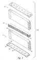
- Figure 5 generally illustrates a receptacle assembly 20 not belonging to the present invention.
- the receptacle assembly 20 incorporates a pair of opposing end assemblies 21 that engage a fuel cell stack 22 from opposing ends during use.
- the end assemblies 21 are substantially identical to each other. Accordingly, the description of one end assembly 21 will serve to describe both end assemblies except where specifically described otherwise.
- the end assembly 21 is fabricated from a convex sidewall 24, a concave sidewall 26, and an end cap 28.
- the convex sidewall 24 and concave sidewall 26 can be fabricated from a thin, insulative material such as LEXAN or a similar material, and can be thermoplastically deformed to conform to a corresponding wall of the fuel cell stack 22.
- the end cap 28 can also be fabricated an insulative material such as LEXAN, and can be vacuum formed to conform with an end of the fuel cell stack 22.
- the end cap 28 can contain a number of openings 30 configured to align with ports on the fuel cell stack 22 or to vent the receptacle assembly 20 during compression as discussed below.
- the opening configuration of Figure 5 is one particular example, but the inventor appreciates that the configuration can and will likely vary for each particular application.
- Each of the sidewalls 24/26 is slightly taller than one-half of the height of a fuel cell stack 22. Consequently, when the end assemblies 21 are engaged with the fuel cell stack 22 from opposing ends, the concave sidewalls 26 overlap each other and the convex sidewalls 24 overlap each other.
- the respective lengths of the sidewalls 24/26 can vary.
- the convex sidewall 24 approaches the concave sidewall 26 at opposing gaps 32 aligned with the ends of the fuel cell stack 22.
- the gaps 32 extend along the entire height of the end assembly 21. The sizes and placements of the gaps 32 can vary and the gaps could be replaced with openings or other suitable features.
- Figures 6-8 further illustrate one particular end assembly 21.
- the convex sidewall 24 and the concave sidewall 26 are each abutted against the end cap 28 and positioned internal to a raised rim 34 extending around the perimeter of the end cap.
- the sidewalls 24/26 are attached to the end cap 28, such as by high frequency welding or other suitable means. The inventor appreciates that the exact nature of the engagement between the sidewalls 24/26 and the end caps 28 can vary.
- FIG 9 illustrates four receptacle assemblies 20 engaged with a manifold 36.
- each receptacle assembly 20 and fuel cell stack 22 was assembled as discussed above and illustrated in Figure 5.
- Each receptacle assembly 20 and fuel cell stack 22 may be individually compressed in a vertical direction as oriented in Figure 9, and may be individually pressure tested for leaks.
- the upper and lower end assemblies 21 can be affixed with adhesive 38 to the sides of the fuel cell stacks 22 through the gaps 32.
- the adhesive 38 is a high tensile strength tape.
- the adhesive 38 connects the sidewalls 24/26 to each other and to the fuel cell stack 22, and thus help retain the fuel cell stack in the stack configuration.
- the adhesive 38 can also retain the fuel cell stack 22 in at least a partially compressed state for a limited duration of time. During this duration, the receptacle assembly 20 can create an insulative barrier around the fuel cell stack 22 which allows the stack to be handled and moved without contaminating the stack or shorting a fuel cell.
- the methods and systems of this particular embodiment have a number of advantages. For example, because the fuel cell stacks 22 can be compressed and pressure tested independently, a failed pressure test results in only a single stack being disassembled, as opposed to an entire multi-stack fuel cell assembly being disassembled. Further, the sidewalls 24/26 serve to isolate the adjacent fuel cell stacks 22 electrically to reduce the potential for a short between the two. Further, because each end assembly 21 overlaps the other, if the fuel cell stack 22 is compressed within the receptacle assembly 20, the end assemblies will not buckle, but will instead slide with respect to each other.
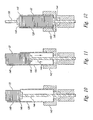
- FIGs 10-12 sequentially illustrate some of the steps in the assembly and compression of a receptacle assembly 120 and fuel cell stack 22 according to an embodiment of the present invention.
- the receptacle assembly 120 is in the form of a box having an open top for receiving the fuel cell stack 22.
- the receptacle assembly 120 is shaped and sized to conform with the fuel cell stack 22.
- the sides, bottom, and other portions of the receptacle assembly 120 can have openings therein for mating with external structures such as the manifold of Figure 9.
- a number of straps 140 are spaced apart from each other along the width of the receptacle assembly 120.
- the receptacle assembly 120 is retained from below such as by a foundation 142.
- One or more pistons 144 extends through the foundation 142 and an opening in the receptacle assembly 120, and projects upward toward the top of the receptacle assembly.
- the piston 144 is configured to support a buss plate 146 and the buss plate is configured to engage the fuel cell stack 22. As illustrated in Figure 11, the piston 144, and with it the buss plate 146 and fuel cell stack 22, move downward into the receptacle assembly 120.
- an upper buss plate 148 is positioned on top of the fuel cell stack.
- a compression mechanism 150 compresses the fuel cell stack 22 against the foundation 142. Depending on the circumstances, the compression mechanism 150 can compress the fuel cell stack 22 at a reduced force for pressure and leak testing, or the compression mechanism can compress the fuel cell stack to full operating compression. During compression, air may escape from the receptacle assembly 120 through openings such as those designated at 30 in Figure 5.
- the strap 140 or plurality of straps 140 are folded across the top of the fuel cell stack and are attached, such as by high frequency welding or other suitable means, to the opposing side of the receptacle assembly 120. Once the straps 140 are welded to the opposing sidewall of the receptacle assembly 120, the particular fuel cell stack is isolated and compressed for assembly into a multi-stack fuel cell.
- the receptacle assembly can be made from an electrically insulative material to facilitate handling and prevent the fuel cell from shorting, such as through contact with an adjacent fuel cell.
- the compressed fuel cell stack can be pressure-tested prior to assembly into the multi-stack fuel cell assembly.
- Figure 13 illustrates a receptacle assembly 220 not belonging to the present invention.
- the receptacle assembly 220 incorporates a pair of opposing end caps 228 and an intermediate sidewall 229.
- the end caps are vacuum formed thermoplastic polymers, such as those described above, and the sidewall 229 is a continuous, extruded tube cut to the length of a compressed fuel cell stack (not shown).
- the sidewall 229 can be vacuum formed to take the shape of a fuel cell stack.
- the end caps 228 and sidewall 229 can have various openings therein to mate with complementary external ports or openings.
- the end caps can contain openings for receiving pistons and compression mechanisms to compress the fuel cell stack. Once the fuel cell stack has been compressed the desired amount, the end caps 228 can be affixed to the sidewall 229 to retain the fuel cell stack in its stack configuration and, if desired, to retain the stack under compression.
- Figure 14 illustrates a receptacle assembly 320 not belonging to the present invention.
- the sidewall 329 is formed from a single sheet of material.
- the sidewall is punched or otherwise cut into a pattern that can be folded to conform to the external surface of a fuel cell stack (not shown).
- the folded receptacle assembly 320 can be vacuum formed and thermoplastically deformed to conform to the fuel cell stack during use.
- the receptacle assembly 320 has a number of fasteners 340 oriented to extend over the top and bottom of the fuel cell stack. After being compressed in a manner similar to that described above, the fasteners 340 can be attached to opposing fasteners or to the opposing sidewall of the receptacle assembly 320 to retain the fuel cell stack in its stack configuration and/or under at least partial compression.
Landscapes
- Life Sciences & Earth Sciences (AREA)
- Engineering & Computer Science (AREA)
- Manufacturing & Machinery (AREA)
- Sustainable Development (AREA)
- Sustainable Energy (AREA)
- Chemical & Material Sciences (AREA)
- Chemical Kinetics & Catalysis (AREA)
- Electrochemistry (AREA)
- General Chemical & Material Sciences (AREA)
- Fuel Cell (AREA)
Abstract
Description
- The present invention relates to electrochemical energy converters with polymer electrolyte membranes, such as fuel cells or electrolyzer cells or stacks of such cells. In particular, the present invention relates to systems and methods for assembling, compressing, isolating, and/or retaining stacks during and/or following fabrication.
- Electrochemical cells comprising polymer electrolyte membranes ("PEM"s) may be operated as fuel cells wherein a fuel and an oxidant are electrochemically converted at the cell electrodes to produce electrical power, or as electrolyzers wherein an external electrical current is passed between the cell electrodes, typically through water, resulting in generation of hydrogen and oxygen at the respective electrodes. Figures 1-4 collectively illustrate typical designs of a conventional
membrane electrode assembly 5, anelectrochemical cell 10 comprising a PEM layer 2, and astack 100 of such cells. - Each
cell 10 comprises a membrane electrode assembly ("MEA") 5 such as that illustrated in an exploded view in Figure 1. MEA 5 comprises an ion-conducting PEM layer 2 interposed between first and second electrode layers 1/3 which are typically porous and electrically conductive, and each of which comprises an electrocatalyst at its interface with the PEM layer for promoting the desired electrochemical reaction. The electrocatalyst generally defines the electrochemically active area of the cell. TheMEA 5 is typically consolidated as a bonded, laminated assembly. - In an
individual cell 10, illustrated in an exploded view in Figure 2, anMEA 5 is interposed between first and secondcell separator plates 11/12, which are typically fluid impermeable and electrically conductive. Thecell separator plates 11/12 are manufactured from non-metals, such as graphite; from metals, such as certain grades of steel or surface treated metals; or from electrically conductive plastic composite materials. - Fluid flow spaces, such as passages or chambers, are provided between the
cell separator plates 11/12 and the adjacent electrode layers 1/3 to facilitate access of reactants to the electrode layers and removal of products. Such spaces may, for example, be provided by means of spacers between theseparator plates 11/12 and the corresponding electrode layers 1/3, or by provision of a mesh or porous fluid flow layer between the cell separator plates and corresponding electrode layers. More commonly, channels are formed in the faces of thecell separator plates 11/12 that face the electrode layers 1/3.Cell separator plates 11/12 comprising such channels are commonly referred to as fluid flow field plates. Inconventional cells 10, resilient gaskets or seals are typically provided around the perimeter of the flow fields between the faces of theMEA 5 and each of thecell separator plates 11/12 to prevent leakage of fluid reactant and product streams. -
Electrochemical cells 10 with ion-conductive PEM layers 2, sometimes called PEM cells, are advantageously stacked to form a stack 100 (see Figure 4) comprising a plurality of cells disposed between first andsecond end plates 17/18. A compression mechanism is typically employed to hold thecells 10 tightly together, to maintain good electrical contact between components, and to compress the seals. In the embodiment illustrated in Figure 3, eachcell 10 comprises a pair ofcell separator plates 11/12 in a configuration with two cell separator plates perMEA 5. Cooling spaces or layers may be provided between some or all of the adjacent pairs ofcell separator plates 11/12 in thestack 100. An alternate configuration (not shown) has a single separator plate, or "bipolar plate," interposed between a pair ofMEAs 5 contacting the cathode of one cell and the anode of the adjacent cell, thus resulting in only one separator plate perMEA 5 in the stack 100 (except for the end cell). Such astack 100 may comprise a cooling layer interposed between everyfew cells 10 of the stack, rather than between each adjacent pair of cells. - The illustrated cell elements have
openings 30 formed therein which, in the stacked assembly, align to form fluid manifolds for supply and exhaust of reactants and products and, if cooling spaces are provided, for a cooling medium. Again, resilient gaskets or seals are typically provided between the faces of theMEA 5 and each of thecell separator plates 11/12 around the perimeter of thesefluid manifold openings 30 to prevent leakage and intermixing of fluid streams in theoperating stack 100. - EP 1 045 468 A2 discloses a fuel cell stack comprising a fuel cell laminate body prepared by laminating a plurality of fuel cells in a vertical direction. The fuel cell laminate body is fastened in the direction of lamination by a fastening means. The fastening means comprises support members equipped with flanges and arranged on upper and lower surfaces of the laminate body, connecting members made of thin plates fixed to edge portions of the support members and a fastening tool for fastening the connecting members in the vertical direction of the laminate body. The fuel cell laminate body and the fastening means thus collectively form the fuel cell stack.
- JP 090 92 324 A describes a fuel cell module comprising a fuel cell stack which is laminated by applying a directional pressing force. A module forming member extends across a sidewall of the fuel cell stack and is fastened to the fuel cell stack by means of bent portions each engaging a respective recess formed in top and bottom surfaces of the fuel cell stack.
- US 4,642,274 relates to a fuel cell stack which is fastened tight with tie bars and tie rods, wherein the tie bars extend across an upper and a lower surface of the fuel cell stack. Frames are applied to respective sides of the fuel cell stack, wherein sealing members are mounted in front and rear faces of each frame to form a seal between the stack and the frame and between the frame and manifolds mounted on pairs of opposite sides of the stack.
- WO 02/27 836 A2, a prior art document which was published after the priority date of the present application, discloses a fuel cell module comprising, a plurality of fuel cells forming a fuel cell stack which is surrounded by a stabilizing casing.
- US 5,213,909 describes a fuel cell stack body comprising a plurality of fuel cells and thermal insulators which are provided on the sides of the fuel cell stack body so as to keep the fuel cells warm. The thermal insulators consist of porous alumina.
- JP 020 49 360 A discloses a fuel cell stack, wherein a plurality of constant-load springs are stretched between upper and lower end plates of the stack to fasten the cell stack in the upper and lower direction.
- US 5,993,987 describes a fuel cell stack, wherein compression bands extend tightly around end plate assemblies and fuel cell assemblies to retain and secure the stack in its assembled state.
- The present invention relates to apparatus, systems and methods for use in fabricating fuel cell stacks and multi-stack fuel cell assemblies. In one embodiment, the present invention incorporates a receptacle for receiving and retaining a fuel cell stack in its stacked configuration during fabrication of the multi-stack fuel cell assembly. The receptacle has an end cap, a pliable sidewall, and a fastener. The end cap has a plurality of openings configured to allow the fuel cell stack to communicate with a corresponding plurality of openings in a manifold. The pliable sidewall is sized and shaped to cover a corresponding sidewall of the fuel cell stack so as to electrically insulate the fuel cell stack from at least one adjacent fuel cell stack when the multi-stack fuel cell has been assembled. The fastener is configured to extend from one location on the sidewall across the end of the fuel cell stack opposite the end cap, and to be attached to another location on the sidewall to retain the fuel cell stack in its stacked configuration. In particular embodiments, the sidewall can be coupled to the end cap, the sidewall can be sized to extend around at least substantially the entire perimeter of a fuel cell stack, the fastener can be a single band, the fastener can be a number of bands, or the fastener can be a portion of the sidewall itself. Other variations are also appreciated. The receptacle can be configured to retain the fuel cell stack in its stacked configuration, and/or can be configured to be tensioned around at least a portion of a compressed stack and adhered thereto to retain the stack under at least partial compression.
- Another embodiment of the present invention is directed toward a method for fabricating a fuel cell stack. The method incorporates placing a stack of fuel cell elements in an open end of a pliable bag having the open end, an opposing closed end and a sidewall therebetween; compressing the fuel cell stack; extending a length of material over the compressed stack and across the open end of the bag; and attaching the length of material to the bag to retain the fuel cell stack in its stack configuration. Embodiments of this invention can be configured to retain the stack under at least partial compression.
- Another method for assembling a plurality of fuel cells does not form a part of the present invention. The method incorporates compressing each of the fuel cell stacks; wrapping a pliable material around each of the stacks of fuel cells to retain the stacks in their stacked configuration; and placing the plurality of stacks between a pair of manifolds. Embodiments of this method can be configured to insulate each fuel cell stack from adjacent fuel cell stacks, and/or to retain the fuel cell stacks under at least partial compression during assembly. Embodiments of this method can also incorporate leak testing each fuel cell stack prior to assembly.
-
- Figure 1
- is an exploded isometric view of a membrane electrode assembly according to the prior art.
- Figure 2
- is an exploded isometric view of an electrochemical cell according to the prior art.
- Figure 3
- is an exploded isometric view of an electrochemical cell stack according to the prior art.
- Figure 4
- is an isometric view of an electrochemical cell stack according to the prior art.
- Figure 5
- is an exploded isometric view of a receptacle not belonging to the present invention.
- Figure 6
- is an elevation view of a lower portion of the receptacle of Figure 5.
- Figure 7
- is a top view of the portion of the receptacle of Figure 6.
- Figure 8
- is an end view of the portion of the receptacle of Figure 6.
- Figure 9
- is an isometric view of four assembled receptacles and fuel cell stacks according to the embodiment of Figure 5.
- Figure 10
- is an end view schematically illustrating one step in the insertion of a fuel cell stack into a receptacle according to an embodiment of the present invention.
- Figure 11
- is an end view schematically illustrating another step in the insertion of the fuel cell stack into the receptacle of Figure 10.
- Figure 12
- is an end view schematically illustrating still another step in the insertion of the fuel cell stack into the receptacle of Figure 10.
- Figure 13
- is an exploded isometric view of a sidewall and a pair of opposing end caps not belonging to the present invention.
- Figure 14
- is an elevation view of a pattern for a receptacle not belonging to the present invention.
- The present detailed description is generally directed toward methods, systems, and apparatus for facilitating the stacking and compression of fuel cell stacks, and the assembly of multi-stack fuel cell assemblies. Various embodiments of the present invention can allow a fuel cell stack to be fabricated and compressed, then sealed in its compressed form for ease of handling and subsequent assembly. Further, embodiments of the invention can isolate adjacent fuel cell stacks in a multi-stack assembly to reduce the potential for electrical shorts. Still further, pre-compression of independent fuel cell stacks can allow the stacks to be leak tested prior to assembly into the multi-stack assembly.
- Many specific details of certain embodiments of the invention are set forth in the following description and illustrated in Figures 5-14 to provide a thorough understanding of such embodiments. Once skilled in the art, however, will understand that the present invention may have additional embodiments, or may be practiced without several of the details described in the following description.
- Figure 5 generally illustrates a
receptacle assembly 20 not belonging to the present invention. Thereceptacle assembly 20 incorporates a pair of opposingend assemblies 21 that engage afuel cell stack 22 from opposing ends during use. In the illustrated embodiment, theend assemblies 21 are substantially identical to each other. Accordingly, the description of oneend assembly 21 will serve to describe both end assemblies except where specifically described otherwise. - The
end assembly 21 is fabricated from aconvex sidewall 24, aconcave sidewall 26, and anend cap 28. Theconvex sidewall 24 andconcave sidewall 26 can be fabricated from a thin, insulative material such as LEXAN or a similar material, and can be thermoplastically deformed to conform to a corresponding wall of thefuel cell stack 22. Theend cap 28 can also be fabricated an insulative material such as LEXAN, and can be vacuum formed to conform with an end of thefuel cell stack 22. Theend cap 28 can contain a number ofopenings 30 configured to align with ports on thefuel cell stack 22 or to vent thereceptacle assembly 20 during compression as discussed below. The opening configuration of Figure 5 is one particular example, but the inventor appreciates that the configuration can and will likely vary for each particular application. - Each of the
sidewalls 24/26 is slightly taller than one-half of the height of afuel cell stack 22. Consequently, when theend assemblies 21 are engaged with thefuel cell stack 22 from opposing ends, theconcave sidewalls 26 overlap each other and theconvex sidewalls 24 overlap each other. The respective lengths of thesidewalls 24/26 can vary. - The
convex sidewall 24 approaches theconcave sidewall 26 at opposinggaps 32 aligned with the ends of thefuel cell stack 22. In the illustrated embodiment, thegaps 32 extend along the entire height of theend assembly 21. The sizes and placements of thegaps 32 can vary and the gaps could be replaced with openings or other suitable features. - Figures 6-8 further illustrate one
particular end assembly 21. When theend assembly 21 is assembled, theconvex sidewall 24 and theconcave sidewall 26 are each abutted against theend cap 28 and positioned internal to a raisedrim 34 extending around the perimeter of the end cap. Thesidewalls 24/26 are attached to theend cap 28, such as by high frequency welding or other suitable means. The inventor appreciates that the exact nature of the engagement between the sidewalls 24/26 and the end caps 28 can vary. - Figure 9 illustrates four
receptacle assemblies 20 engaged with a manifold 36. Prior to being configured as such, eachreceptacle assembly 20 andfuel cell stack 22 was assembled as discussed above and illustrated in Figure 5. Eachreceptacle assembly 20 andfuel cell stack 22 may be individually compressed in a vertical direction as oriented in Figure 9, and may be individually pressure tested for leaks. Upon receiving confirmation that there are no leaks in a particularfuel cell stack 22, the upper andlower end assemblies 21 can be affixed with adhesive 38 to the sides of the fuel cell stacks 22 through thegaps 32. In the illustrated embodiment, the adhesive 38 is a high tensile strength tape. Accordingly, the adhesive 38 connects thesidewalls 24/26 to each other and to thefuel cell stack 22, and thus help retain the fuel cell stack in the stack configuration. The adhesive 38 can also retain thefuel cell stack 22 in at least a partially compressed state for a limited duration of time. During this duration, thereceptacle assembly 20 can create an insulative barrier around thefuel cell stack 22 which allows the stack to be handled and moved without contaminating the stack or shorting a fuel cell. - The methods and systems of this particular embodiment have a number of advantages. For example, because the fuel cell stacks 22 can be compressed and pressure tested independently, a failed pressure test results in only a single stack being disassembled, as opposed to an entire multi-stack fuel cell assembly being disassembled. Further, the
sidewalls 24/26 serve to isolate the adjacent fuel cell stacks 22 electrically to reduce the potential for a short between the two. Further, because eachend assembly 21 overlaps the other, if thefuel cell stack 22 is compressed within thereceptacle assembly 20, the end assemblies will not buckle, but will instead slide with respect to each other. - Figures 10-12 sequentially illustrate some of the steps in the assembly and compression of a
receptacle assembly 120 andfuel cell stack 22 according to an embodiment of the present invention. Thereceptacle assembly 120 is in the form of a box having an open top for receiving thefuel cell stack 22. Thereceptacle assembly 120 is shaped and sized to conform with thefuel cell stack 22. As with the prior embodiment, the sides, bottom, and other portions of thereceptacle assembly 120 can have openings therein for mating with external structures such as the manifold of Figure 9. A number ofstraps 140 are spaced apart from each other along the width of thereceptacle assembly 120. - During assembly, the
receptacle assembly 120 is retained from below such as by afoundation 142. One ormore pistons 144 extends through thefoundation 142 and an opening in thereceptacle assembly 120, and projects upward toward the top of the receptacle assembly. Thepiston 144 is configured to support abuss plate 146 and the buss plate is configured to engage thefuel cell stack 22. As illustrated in Figure 11, thepiston 144, and with it thebuss plate 146 andfuel cell stack 22, move downward into thereceptacle assembly 120. - As illustrated in Figure 12, once the
fuel cell stack 22 has been completely received by thereceptacle assembly 120, anupper buss plate 148 is positioned on top of the fuel cell stack. Acompression mechanism 150 compresses thefuel cell stack 22 against thefoundation 142. Depending on the circumstances, thecompression mechanism 150 can compress thefuel cell stack 22 at a reduced force for pressure and leak testing, or the compression mechanism can compress the fuel cell stack to full operating compression. During compression, air may escape from thereceptacle assembly 120 through openings such as those designated at 30 in Figure 5. - When the
fuel cell stack 22 is compressed to the desired amount, thestrap 140 or plurality ofstraps 140 are folded across the top of the fuel cell stack and are attached, such as by high frequency welding or other suitable means, to the opposing side of thereceptacle assembly 120. Once thestraps 140 are welded to the opposing sidewall of thereceptacle assembly 120, the particular fuel cell stack is isolated and compressed for assembly into a multi-stack fuel cell. As discussed above, the receptacle assembly can be made from an electrically insulative material to facilitate handling and prevent the fuel cell from shorting, such as through contact with an adjacent fuel cell. In addition, the compressed fuel cell stack can be pressure-tested prior to assembly into the multi-stack fuel cell assembly. - Figure 13 illustrates a
receptacle assembly 220 not belonging to the present invention. In this particular embodiment, thereceptacle assembly 220 incorporates a pair of opposingend caps 228 and anintermediate sidewall 229. In the illustrated embodiment, the end caps are vacuum formed thermoplastic polymers, such as those described above, and thesidewall 229 is a continuous, extruded tube cut to the length of a compressed fuel cell stack (not shown). As discussed above, thesidewall 229 can be vacuum formed to take the shape of a fuel cell stack. - Similar to those embodiments discussed above, the end caps 228 and
sidewall 229 can have various openings therein to mate with complementary external ports or openings. Likewise, the end caps can contain openings for receiving pistons and compression mechanisms to compress the fuel cell stack. Once the fuel cell stack has been compressed the desired amount, the end caps 228 can be affixed to thesidewall 229 to retain the fuel cell stack in its stack configuration and, if desired, to retain the stack under compression. - Figure 14 illustrates a
receptacle assembly 320 not belonging to the present invention. In this particular embodiment, thesidewall 329 is formed from a single sheet of material. The sidewall is punched or otherwise cut into a pattern that can be folded to conform to the external surface of a fuel cell stack (not shown). The foldedreceptacle assembly 320 can be vacuum formed and thermoplastically deformed to conform to the fuel cell stack during use. - The
receptacle assembly 320 has a number offasteners 340 oriented to extend over the top and bottom of the fuel cell stack. After being compressed in a manner similar to that described above, thefasteners 340 can be attached to opposing fasteners or to the opposing sidewall of thereceptacle assembly 320 to retain the fuel cell stack in its stack configuration and/or under at least partial compression.
Claims (26)
- A method for fabricating a fuel cell stack, comprising:placing a stack of fuel cell elements (22) in an open end of a pliable bag (120) having the open end, an opposing closed end and a sidewall therebetween;compressing the fuel cell stack (22);extending a length of material over the compressed stack (22) and across the open end of the bag (120); andattaching the length of material to the bag (120) to retain the fuel cell stack (22) in its stack configuration.
- The method of claim 1 wherein placing a stack of fuel cell elements (22) in the open end of the bag (120) comprises separately placing each fuel cell element into the bag (120), one at a time.
- The method of claim 1 wherein placing a stack of fuel cell elements (22) in the open end of the bag (120) comprises separately placing groups of fuel cell elements into the bag, one group at a time.
- The method of claim 1 wherein placing a stack of fuel cell elements (22) in the open end of the bag (120) comprises placing the fuel cell stack (22) onto a buss plate (146), then lowering the buss plate (146) into the bag (120).
- The method of claim 1, further comprising first placing a sealing element against the closed end of the bag (120) such that the fuel cell element abutting the closed end of the bag (120) is in sealing contact therewith.
- The method of claim 1 wherein compressing the fuel cell stack (22) comprises compressing the fuel cell stack (22) while the stack (22) is in the bag (120).
- The method of claim 1 wherein the open end of the bag (120) has a tab (140) projecting therefrom, and wherein extending a length of material over the compressed stack (22) and across the open end of the bag (120) comprises folding the tab (140) from a first location on the sidewall of the bag (120) to a second location on the sidewall of the bag (120) opposite the first location.
- The method of claim 1 wherein the open end of the bag (120) has a plurality of tabs (140) projecting therefrom, and wherein extending a length of material over the compressed stack (22) and across the open end of the bag (120) comprises folding the plurality of tabs (140), each from a first location on the sidewall of the bag (120) to a second location on the sidewall of the bag (120) opposite the first location.
- The method of claim 1 wherein extending a length of material over the compressed stack (22) and across the open end of the bag (120) comprises extending a band of material from the closed end of the bag (120).
- The method of claim 1 wherein extending a length of material over the compressed stack (22) and across the open end of the bag (120) comprises extending a band of material to the closed end of the bag (120).
- The method of claim 1 wherein extending a length of material over the compressed stack (22) and across the open end of the bag (120) comprises extending a band of material from a first location on the closed end of the bag (120) to a second location on the closed end of the bag (120).
- The method of claim 1 wherein extending a length of material over the compressed stack (22) and across the open end of the bag (120) comprises folding a portion of the sidewall across the stack (22).
- The method of claim 1 wherein the bag (120) further comprises a second closed end, and wherein extending a length of material over the compressed stack (22) comprises placing the second closed end over the stack (22).
- The method of claim 1 wherein attaching the length of material to the bag (120) to retain the fuel cell stack (22) in its stack configuration comprises tensioning the length of material such that the fuel cell stack (22) remains at least partially compressed.
- The method of claim 1 wherein the sidewall of the pliable bag (120) has a height less than a corresponding height of the stack of fuel cells (22), and wherein extending a length of material over the compressed stack (22) and across the open end of the bag (120) comprises engaging a cap having a sleeve depending therefrom over the top of the stack of fuel cells (22) such that the sleeve of the cap overlaps the sidewall of the pliable bag (120).
- The method of claim 1 wherein the sidewall of the pliable bag (120) has a height less than a corresponding height of the stack of fuel cells (22), and wherein extending a length of material over the compressed stack (22) and across the open end of the bag (120) comprises engaging a cap having a sleeve depending therefrom over the top of the stack of fuel cells (22) such that the sleeve of the cap overlaps the sidewall of the pliable bag (120), and further comprising taping the sidewall of the bag (120) to the sleeve on the cap to retain the stack (22) in its stacked configuration.
- The method of claim 1 wherein the sidewall of the pliable bag (120) has a height less than a corresponding height of the stack of fuel cells (22), and wherein extending a length of material over the compressed stack (22) and across the open end of the bag (120) comprises engaging a cap having a sleeve depending therefrom over the top of the stack of fuel cells (22) such that the sleeve of the cap overlaps the sidewall of the pliable bag (120), and further comprising tensioning the sidewall and the sleeve away from their respective ends and taping the sidewall of the bag (120) to the sleeve on the cap to retain the stack (22) in its stacked configuration under at least partial compression.
- A receptacle (120) for receiving and retaining a fuel cell stack (22) in its stacked configuration during fabrication of a multi-stack fuel cell assembly having a manifold, the receptacle (120) comprising:an end cap having a plurality of openings therein configured to allow the fuel cell stack (22) to communicate with a corresponding plurality of openings in the manifold;a pliable sidewall sized and shaped to cover a corresponding sidewall of the fuel.cell stack (22) so as to insulate the fuel cell stack (22) from at least one adjacent fuel cell stack (22) when the multi-stack fuel cell assembly has been assembled; anda fastener (140) configured to extend from one location on the sidewall across the end of the fuel cell stack (22) opposite the end cap and to be attached to another location on the sidewall to retain the fuel cell stack (22) in its stacked configuration.
- The receptacle of claim 18 wherein the end cap is formed to conform to the shape of an end of the fuel cell stack (22).
- The receptacle of claim 18 wherein the end cap comprises a thermoplastic resin that is vacuum formed to conform to the shape of and end of the fuel cell stack (22).
- The receptacle of claim 18 wherein an internal surface of the end cap comprises a seal around at least one of the openings, the seal being configured to sealably engage a port on the fuel cell stack (22) to reduce the likelihood of leakage between the fuel cell stack (22) and the manifold.
- The receptacle of claim 18 wherein the sidewall is coupled to the end cap.
- The receptacle of claim 18 wherein the sidewall is sized to extend around the entire perimeter of the fuel cell stack (22).
- The receptacle of claim 18 wherein the fastener (140) comprises an elongated band of pliable material having a length sufficient to extend across the top of the fuel cell stack (22) and overlap an opposing portion of the sidewall.
- The receptacle of claim 18 wherein the fastener (140) comprises a plurality of elongated bands of pliable material, each band having a length sufficient to extend across the top of the fuel cell stack (22) and overlap an opposing portion of the sidewall.
- The receptacle of claim 18 wherein the fastener (140) comprises a portion of the sidewall sufficiently tall to project beyond a corresponding top of the fuel cell stack (22) when the fuel cell stack (22) is engaged with the receptacle, such that the portion of the sidewall can be folded across the top of the fuel cell stack (22) and overlap at least a portion of an opposing portion of the sidewall.
Priority Applications (1)
| Application Number | Priority Date | Filing Date | Title |
|---|---|---|---|
| EP06013735A EP1703580B1 (en) | 2001-11-30 | 2002-11-26 | Method for assembling a plurality of fuel cells stacks. |
Applications Claiming Priority (2)
| Application Number | Priority Date | Filing Date | Title |
|---|---|---|---|
| US09/999,178 US6862801B2 (en) | 2001-11-30 | 2001-11-30 | Systems, apparatus and methods for isolating, compressing and/or retaining the structure of a fuel cell stack |
| US999178 | 2001-11-30 |
Related Child Applications (1)
| Application Number | Title | Priority Date | Filing Date |
|---|---|---|---|
| EP06013735A Division EP1703580B1 (en) | 2001-11-30 | 2002-11-26 | Method for assembling a plurality of fuel cells stacks. |
Publications (2)
| Publication Number | Publication Date |
|---|---|
| EP1341252A1 EP1341252A1 (en) | 2003-09-03 |
| EP1341252B1 true EP1341252B1 (en) | 2007-01-17 |
Family
ID=25545993
Family Applications (2)
| Application Number | Title | Priority Date | Filing Date |
|---|---|---|---|
| EP02026402A Expired - Lifetime EP1341252B1 (en) | 2001-11-30 | 2002-11-26 | Systems and methods for isolating, compressing and retaining the structure of a fuel cell stack |
| EP06013735A Expired - Lifetime EP1703580B1 (en) | 2001-11-30 | 2002-11-26 | Method for assembling a plurality of fuel cells stacks. |
Family Applications After (1)
| Application Number | Title | Priority Date | Filing Date |
|---|---|---|---|
| EP06013735A Expired - Lifetime EP1703580B1 (en) | 2001-11-30 | 2002-11-26 | Method for assembling a plurality of fuel cells stacks. |
Country Status (4)
| Country | Link |
|---|---|
| US (1) | US6862801B2 (en) |
| EP (2) | EP1341252B1 (en) |
| AT (2) | ATE352105T1 (en) |
| DE (2) | DE60230339D1 (en) |
Families Citing this family (13)
| Publication number | Priority date | Publication date | Assignee | Title |
|---|---|---|---|---|
| AU6157898A (en) * | 1997-02-06 | 1998-08-26 | E. Heller & Company | Small volume (in vitro) analyte sensor |
| DE112004002237B4 (en) * | 2003-11-20 | 2010-03-11 | Nissan Motor Co., Ltd., Yokohama-shi | Method and device for producing a fuel cell |
| US20060006155A1 (en) * | 2004-07-08 | 2006-01-12 | Hill Graham E | Device for assembling a banded fuel cell stack |
| US7807309B2 (en) * | 2004-09-03 | 2010-10-05 | Gm Global Technology Operations, Inc. | Integrated coolant header venting for a fuel cell stack |
| US20090226774A1 (en) * | 2007-08-02 | 2009-09-10 | Ross Salvatore Friscia | Regenerative Cell |
| GB0715218D0 (en) * | 2007-08-03 | 2007-09-12 | Rolls Royce Fuel Cell Systems | A fuel cell and a method of manufacturing a fuel cell |
| CA2659525A1 (en) * | 2008-03-25 | 2009-09-25 | Bdf Ip Holdings Ltd. | Fuel cell system with fuel cell stack receptacle |
| DE102012000266A1 (en) | 2012-01-10 | 2013-07-11 | Daimler Ag | fuel cell stack |
| JP5737198B2 (en) * | 2012-01-23 | 2015-06-17 | トヨタ自動車株式会社 | Fuel cell |
| ES2734527T3 (en) | 2013-03-08 | 2019-12-10 | Nuvera Fuel Cells Llc | Electrochemical stacking |
| GB2563848B (en) * | 2017-06-26 | 2022-01-12 | Ceres Ip Co Ltd | Fuel cell stack assembly |
| US11746427B2 (en) | 2021-07-05 | 2023-09-05 | EvolOH, Inc. | Scalable electrolysis cell and stack and method of high-speed manufacturing the same |
| DE102022214236A1 (en) * | 2022-12-21 | 2024-06-27 | Robert Bosch Gesellschaft mit beschränkter Haftung | Method for property-related arrangement of fuel cells within a fuel cell stack |
Family Cites Families (23)
| Publication number | Priority date | Publication date | Assignee | Title |
|---|---|---|---|---|
| US4218526A (en) | 1978-04-11 | 1980-08-19 | General Battery Corporation | Industrial battery stack |
| JPS61116769A (en) | 1984-11-12 | 1986-06-04 | Sanyo Electric Co Ltd | Stack frame fastening device of fuel cell |
| US4842962A (en) | 1988-04-11 | 1989-06-27 | Bass Robert H | Fuel cell and mold therefor |
| JPH0249360A (en) | 1988-08-10 | 1990-02-19 | Sanyo Electric Co Ltd | Stacked fuel cell |
| JPH04322064A (en) | 1991-04-23 | 1992-11-12 | Hitachi Ltd | Support structure for side heat insulator of fuel cell |
| US5324565A (en) | 1992-12-17 | 1994-06-28 | United Technologies Corporation | Conductive elastomeric compression pad for use in electrolysis cells |
| US5258242A (en) | 1993-02-08 | 1993-11-02 | Ovonic Battery Company, Inc. | Electrochemical cell having improved pressure vent |
| US5409787A (en) | 1993-02-17 | 1995-04-25 | Electrosource, Inc. | Battery plate compression cage assembly |
| JP3007814B2 (en) * | 1994-10-03 | 2000-02-07 | 大阪瓦斯株式会社 | Fuel cell |
| US5629104A (en) | 1994-11-23 | 1997-05-13 | Detroit Center Tool | Modular electrical energy device |
| JPH0992324A (en) | 1995-07-20 | 1997-04-04 | Toyota Motor Corp | Battery module and fuel cell |
| US5741605A (en) * | 1996-03-08 | 1998-04-21 | Westinghouse Electric Corporation | Solid oxide fuel cell generator with removable modular fuel cell stack configurations |
| GB9610441D0 (en) | 1996-05-17 | 1996-07-24 | Tbs Eng Ltd | Loading apparatus |
| US5789091C1 (en) | 1996-11-19 | 2001-02-27 | Ballard Power Systems | Electrochemical fuel cell stack with compression bands |
| US6001502A (en) | 1997-06-27 | 1999-12-14 | Plug Power, L.L.C. | Current conducting end plate of fuel cell assembly |
| US6162559A (en) | 1998-09-21 | 2000-12-19 | Douglas Battery Manufacturing Company | Compressed battery system for motive power applications |
| US6194095B1 (en) * | 1998-12-15 | 2001-02-27 | Robert G. Hockaday | Non-bipolar fuel cell stack configuration |
| JP4220615B2 (en) | 1999-04-16 | 2009-02-04 | 三菱重工業株式会社 | Fuel cell stack |
| EP1199760B1 (en) * | 1999-05-31 | 2010-04-21 | Central Research Institute of Electric Power Industry | Unit cell of flat solid electrolytic fuel battery and cell stack comprising the same |
| US6218039B1 (en) * | 1999-08-25 | 2001-04-17 | Plug Power, Inc. | Clamping apparatus and method for a fuel cell |
| EP1338050B1 (en) | 2000-09-26 | 2010-12-22 | Siemens Aktiengesellschaft | Fuel cell module |
| US6596427B1 (en) * | 2000-11-06 | 2003-07-22 | Ballard Power Systems Inc. | Encapsulating seals for electrochemical cell stacks and methods of sealing electrochemical cell stacks |
| US6632556B2 (en) * | 2000-12-19 | 2003-10-14 | Utc Fuel Cells, Llc | Manifold assembly for a fuel cell power plant |
-
2001
- 2001-11-30 US US09/999,178 patent/US6862801B2/en not_active Expired - Fee Related
-
2002
- 2002-11-26 AT AT02026402T patent/ATE352105T1/en not_active IP Right Cessation
- 2002-11-26 DE DE60230339T patent/DE60230339D1/en not_active Expired - Lifetime
- 2002-11-26 DE DE60217641T patent/DE60217641T2/en not_active Expired - Lifetime
- 2002-11-26 AT AT06013735T patent/ATE417376T1/en not_active IP Right Cessation
- 2002-11-26 EP EP02026402A patent/EP1341252B1/en not_active Expired - Lifetime
- 2002-11-26 EP EP06013735A patent/EP1703580B1/en not_active Expired - Lifetime
Also Published As
| Publication number | Publication date |
|---|---|
| EP1703580A1 (en) | 2006-09-20 |
| US6862801B2 (en) | 2005-03-08 |
| US20030104260A1 (en) | 2003-06-05 |
| DE60217641T2 (en) | 2007-05-16 |
| ATE417376T1 (en) | 2008-12-15 |
| EP1703580B1 (en) | 2008-12-10 |
| DE60230339D1 (en) | 2009-01-22 |
| DE60217641D1 (en) | 2007-03-08 |
| EP1341252A1 (en) | 2003-09-03 |
| ATE352105T1 (en) | 2007-02-15 |
Similar Documents
| Publication | Publication Date | Title |
|---|---|---|
| KR100876262B1 (en) | Solid Polymer Electrolyte Fuel Cell | |
| US8232015B2 (en) | One-shot fabrication of membrane based electrochemical cell stacks | |
| EP0981174B1 (en) | Polymer electrolyte fuel cell | |
| US6946212B2 (en) | Electrochemical fuel cell stack with improved reactant manifolding and sealing | |
| EP1271678B1 (en) | Systems, apparatus and methods for bonding and/or sealing electrochemical cell elements and assemblies | |
| EP1671390B1 (en) | Seal structure of a fuel cell | |
| US20020034670A1 (en) | Seal for fuel cell and forming method therefor | |
| US20020022170A1 (en) | Integrated and modular BSP/MEA/manifold plates for fuel cells | |
| CA2523988C (en) | Fuel cell | |
| US6862801B2 (en) | Systems, apparatus and methods for isolating, compressing and/or retaining the structure of a fuel cell stack | |
| US20030224237A1 (en) | Membrane electrode assembly for an electrochemical fuel cell | |
| CA2473870A1 (en) | Sealing structure for sealing separator plates of fuel cell modules | |
| EP1932199B1 (en) | Integrated seal for fuel cell assembly and fuel cell stack | |
| CA2976351C (en) | Seal for solid polymer electrolyte fuel cell | |
| EP2273593A3 (en) | Sealing structure for sealing separator plates of fuel cell modules | |
| US9979042B2 (en) | Fuel cell stack | |
| EP1825552B1 (en) | Solid oxide fuel cell with external manifolds | |
| US12249746B2 (en) | Enclosed fuel cell stack row | |
| US7824817B2 (en) | Fuel cell | |
| US20050058897A1 (en) | Reinforced components for electrochemical cells | |
| JP2019133894A (en) | Fuel cell | |
| HK1167747A1 (en) | Compression arrangement for fuel or electrolysis cells in a fuel cell stack or an electrolysis cell stack | |
| HK1167747B (en) | Compression arrangement for fuel or electrolysis cells in a fuel cell stack or an electrolysis cell stack | |
| AU2002363067A1 (en) | One-shot fabrication of membrane-based electrochemical cell stacks |
Legal Events
| Date | Code | Title | Description |
|---|---|---|---|
| PUAI | Public reference made under article 153(3) epc to a published international application that has entered the european phase |
Free format text: ORIGINAL CODE: 0009012 |
|
| AK | Designated contracting states |
Kind code of ref document: A1 Designated state(s): AT BE BG CH CY CZ DE DK EE ES FI FR GB GR IE IT LI LU MC NL PT SE SK TR |
|
| AX | Request for extension of the european patent |
Extension state: AL LT LV MK RO SI |
|
| 17P | Request for examination filed |
Effective date: 20031210 |
|
| AKX | Designation fees paid |
Designated state(s): AT BE BG CH CY CZ DE DK EE ES FI FR GB GR IE IT LI LU MC NL PT SE SK TR |
|
| 17Q | First examination report despatched |
Effective date: 20041214 |
|
| GRAP | Despatch of communication of intention to grant a patent |
Free format text: ORIGINAL CODE: EPIDOSNIGR1 |
|
| GRAS | Grant fee paid |
Free format text: ORIGINAL CODE: EPIDOSNIGR3 |
|
| RAP1 | Party data changed (applicant data changed or rights of an application transferred) |
Owner name: BALLARD POWER SYSTEMS INC. |
|
| GRAA | (expected) grant |
Free format text: ORIGINAL CODE: 0009210 |
|
| AK | Designated contracting states |
Kind code of ref document: B1 Designated state(s): AT BE BG CH CY CZ DE DK EE ES FI FR GB GR IE IT LI LU MC NL PT SE SK TR |
|
| PG25 | Lapsed in a contracting state [announced via postgrant information from national office to epo] |
Ref country code: NL Free format text: LAPSE BECAUSE OF FAILURE TO SUBMIT A TRANSLATION OF THE DESCRIPTION OR TO PAY THE FEE WITHIN THE PRESCRIBED TIME-LIMIT Effective date: 20070117 Ref country code: AT Free format text: LAPSE BECAUSE OF FAILURE TO SUBMIT A TRANSLATION OF THE DESCRIPTION OR TO PAY THE FEE WITHIN THE PRESCRIBED TIME-LIMIT Effective date: 20070117 Ref country code: FI Free format text: LAPSE BECAUSE OF FAILURE TO SUBMIT A TRANSLATION OF THE DESCRIPTION OR TO PAY THE FEE WITHIN THE PRESCRIBED TIME-LIMIT Effective date: 20070117 Ref country code: LI Free format text: LAPSE BECAUSE OF FAILURE TO SUBMIT A TRANSLATION OF THE DESCRIPTION OR TO PAY THE FEE WITHIN THE PRESCRIBED TIME-LIMIT Effective date: 20070117 Ref country code: DK Free format text: LAPSE BECAUSE OF FAILURE TO SUBMIT A TRANSLATION OF THE DESCRIPTION OR TO PAY THE FEE WITHIN THE PRESCRIBED TIME-LIMIT Effective date: 20070117 Ref country code: CH Free format text: LAPSE BECAUSE OF FAILURE TO SUBMIT A TRANSLATION OF THE DESCRIPTION OR TO PAY THE FEE WITHIN THE PRESCRIBED TIME-LIMIT Effective date: 20070117 |
|
| REG | Reference to a national code |
Ref country code: GB Ref legal event code: FG4D |
|
| REG | Reference to a national code |
Ref country code: CH Ref legal event code: EP |
|
| REG | Reference to a national code |
Ref country code: IE Ref legal event code: FG4D |
|
| REF | Corresponds to: |
Ref document number: 60217641 Country of ref document: DE Date of ref document: 20070308 Kind code of ref document: P |
|
| PG25 | Lapsed in a contracting state [announced via postgrant information from national office to epo] |
Ref country code: SE Free format text: LAPSE BECAUSE OF FAILURE TO SUBMIT A TRANSLATION OF THE DESCRIPTION OR TO PAY THE FEE WITHIN THE PRESCRIBED TIME-LIMIT Effective date: 20070417 |
|
| PG25 | Lapsed in a contracting state [announced via postgrant information from national office to epo] |
Ref country code: BG Free format text: LAPSE BECAUSE OF THE APPLICANT RENOUNCES Effective date: 20070418 |
|
| PG25 | Lapsed in a contracting state [announced via postgrant information from national office to epo] |
Ref country code: ES Free format text: LAPSE BECAUSE OF FAILURE TO SUBMIT A TRANSLATION OF THE DESCRIPTION OR TO PAY THE FEE WITHIN THE PRESCRIBED TIME-LIMIT Effective date: 20070428 |
|
| PG25 | Lapsed in a contracting state [announced via postgrant information from national office to epo] |
Ref country code: PT Free format text: LAPSE BECAUSE OF FAILURE TO SUBMIT A TRANSLATION OF THE DESCRIPTION OR TO PAY THE FEE WITHIN THE PRESCRIBED TIME-LIMIT Effective date: 20070618 |
|
| NLV1 | Nl: lapsed or annulled due to failure to fulfill the requirements of art. 29p and 29m of the patents act | ||
| ET | Fr: translation filed | ||
| REG | Reference to a national code |
Ref country code: CH Ref legal event code: PL |
|
| PLBE | No opposition filed within time limit |
Free format text: ORIGINAL CODE: 0009261 |
|
| STAA | Information on the status of an ep patent application or granted ep patent |
Free format text: STATUS: NO OPPOSITION FILED WITHIN TIME LIMIT |
|
| PG25 | Lapsed in a contracting state [announced via postgrant information from national office to epo] |
Ref country code: SK Free format text: LAPSE BECAUSE OF FAILURE TO SUBMIT A TRANSLATION OF THE DESCRIPTION OR TO PAY THE FEE WITHIN THE PRESCRIBED TIME-LIMIT Effective date: 20070117 |
|
| 26N | No opposition filed |
Effective date: 20071018 |
|
| PG25 | Lapsed in a contracting state [announced via postgrant information from national office to epo] |
Ref country code: CZ Free format text: LAPSE BECAUSE OF FAILURE TO SUBMIT A TRANSLATION OF THE DESCRIPTION OR TO PAY THE FEE WITHIN THE PRESCRIBED TIME-LIMIT Effective date: 20070117 Ref country code: BE Free format text: LAPSE BECAUSE OF FAILURE TO SUBMIT A TRANSLATION OF THE DESCRIPTION OR TO PAY THE FEE WITHIN THE PRESCRIBED TIME-LIMIT Effective date: 20070117 |
|
| PG25 | Lapsed in a contracting state [announced via postgrant information from national office to epo] |
Ref country code: IT Free format text: LAPSE BECAUSE OF FAILURE TO SUBMIT A TRANSLATION OF THE DESCRIPTION OR TO PAY THE FEE WITHIN THE PRESCRIBED TIME-LIMIT Effective date: 20070117 Ref country code: GR Free format text: LAPSE BECAUSE OF FAILURE TO SUBMIT A TRANSLATION OF THE DESCRIPTION OR TO PAY THE FEE WITHIN THE PRESCRIBED TIME-LIMIT Effective date: 20070418 |
|
| PG25 | Lapsed in a contracting state [announced via postgrant information from national office to epo] |
Ref country code: MC Free format text: LAPSE BECAUSE OF NON-PAYMENT OF DUE FEES Effective date: 20071130 |
|
| PG25 | Lapsed in a contracting state [announced via postgrant information from national office to epo] |
Ref country code: IE Free format text: LAPSE BECAUSE OF NON-PAYMENT OF DUE FEES Effective date: 20071126 |
|
| PG25 | Lapsed in a contracting state [announced via postgrant information from national office to epo] |
Ref country code: EE Free format text: LAPSE BECAUSE OF FAILURE TO SUBMIT A TRANSLATION OF THE DESCRIPTION OR TO PAY THE FEE WITHIN THE PRESCRIBED TIME-LIMIT Effective date: 20070117 |
|
| PG25 | Lapsed in a contracting state [announced via postgrant information from national office to epo] |
Ref country code: CY Free format text: LAPSE BECAUSE OF FAILURE TO SUBMIT A TRANSLATION OF THE DESCRIPTION OR TO PAY THE FEE WITHIN THE PRESCRIBED TIME-LIMIT Effective date: 20070117 |
|
| PG25 | Lapsed in a contracting state [announced via postgrant information from national office to epo] |
Ref country code: LU Free format text: LAPSE BECAUSE OF NON-PAYMENT OF DUE FEES Effective date: 20071126 |
|
| PG25 | Lapsed in a contracting state [announced via postgrant information from national office to epo] |
Ref country code: TR Free format text: LAPSE BECAUSE OF FAILURE TO SUBMIT A TRANSLATION OF THE DESCRIPTION OR TO PAY THE FEE WITHIN THE PRESCRIBED TIME-LIMIT Effective date: 20070117 |
|
| PGFP | Annual fee paid to national office [announced via postgrant information from national office to epo] |
Ref country code: DE Payment date: 20091120 Year of fee payment: 8 |
|
| PGFP | Annual fee paid to national office [announced via postgrant information from national office to epo] |
Ref country code: FR Payment date: 20091201 Year of fee payment: 8 |
|
| PGFP | Annual fee paid to national office [announced via postgrant information from national office to epo] |
Ref country code: GB Payment date: 20110328 Year of fee payment: 9 |
|
| REG | Reference to a national code |
Ref country code: FR Ref legal event code: ST Effective date: 20110801 |
|
| REG | Reference to a national code |
Ref country code: DE Ref legal event code: R119 Ref document number: 60217641 Country of ref document: DE Effective date: 20110601 Ref country code: DE Ref legal event code: R119 Ref document number: 60217641 Country of ref document: DE Effective date: 20110531 |
|
| PG25 | Lapsed in a contracting state [announced via postgrant information from national office to epo] |
Ref country code: FR Free format text: LAPSE BECAUSE OF NON-PAYMENT OF DUE FEES Effective date: 20101130 |
|
| GBPC | Gb: european patent ceased through non-payment of renewal fee |
Effective date: 20111126 |
|
| PG25 | Lapsed in a contracting state [announced via postgrant information from national office to epo] |
Ref country code: GB Free format text: LAPSE BECAUSE OF NON-PAYMENT OF DUE FEES Effective date: 20111126 |
|
| PG25 | Lapsed in a contracting state [announced via postgrant information from national office to epo] |
Ref country code: DE Free format text: LAPSE BECAUSE OF NON-PAYMENT OF DUE FEES Effective date: 20110531 |