EP1341209A1 - Gas discharge tube - Google Patents
Gas discharge tube Download PDFInfo
- Publication number
- EP1341209A1 EP1341209A1 EP01982793A EP01982793A EP1341209A1 EP 1341209 A1 EP1341209 A1 EP 1341209A1 EP 01982793 A EP01982793 A EP 01982793A EP 01982793 A EP01982793 A EP 01982793A EP 1341209 A1 EP1341209 A1 EP 1341209A1
- Authority
- EP
- European Patent Office
- Prior art keywords
- discharge
- concave portion
- discharge limiting
- opening
- focusing electrode
- Prior art date
- Legal status (The legal status is an assumption and is not a legal conclusion. Google has not performed a legal analysis and makes no representation as to the accuracy of the status listed.)
- Granted
Links
Images




Classifications
-
- H—ELECTRICITY
- H01—ELECTRIC ELEMENTS
- H01J—ELECTRIC DISCHARGE TUBES OR DISCHARGE LAMPS
- H01J61/00—Gas-discharge or vapour-discharge lamps
- H01J61/02—Details
- H01J61/30—Vessels; Containers
-
- H—ELECTRICITY
- H01—ELECTRIC ELEMENTS
- H01J—ELECTRIC DISCHARGE TUBES OR DISCHARGE LAMPS
- H01J61/00—Gas-discharge or vapour-discharge lamps
- H01J61/02—Details
- H01J61/04—Electrodes; Screens; Shields
- H01J61/10—Shields, screens, or guides for influencing the discharge
-
- H—ELECTRICITY
- H01—ELECTRIC ELEMENTS
- H01J—ELECTRIC DISCHARGE TUBES OR DISCHARGE LAMPS
- H01J61/00—Gas-discharge or vapour-discharge lamps
- H01J61/68—Lamps in which the main discharge is between parts of a current-carrying guide, e.g. halo lamp
-
- H—ELECTRICITY
- H01—ELECTRIC ELEMENTS
- H01J—ELECTRIC DISCHARGE TUBES OR DISCHARGE LAMPS
- H01J61/00—Gas-discharge or vapour-discharge lamps
- H01J61/70—Lamps with low-pressure unconstricted discharge having a cold pressure < 400 Torr
Definitions
- the present invention relates particularly to a gas discharge tube for use as a light source in a spectroscope, in chromatography, and so on.
- Japanese Patent Application Laid-open Publication H6-310101 discloses conventional technology in this field.
- a gas (deuterium) discharge tube described in this publication two metallic partition walls are disposed on a discharge path between an anode and a cathode, a small hole is formed in each partition wall, and the discharge path is narrowed by these small holes.
- light of a high luminance can be obtained by means of the small holes on the discharge path. If three or more metallic partition walls are provided, even higher luminance is obtained, and the luminance of the light increases as the small holes are made smaller.
- the present invention has been designed in order to solve the aforementioned problems, and it is a particular object thereof to provide a gas discharge tube in which favorable startability is provided while realizing high luminance.
- a gas discharge tube is caused to discharge a predetermined light toward the outside from a light exit window of a hermetically sealed container by sealing gas inside the hermetically sealed container and generating discharge between an anode portion and a cathode portion disposed within the hermetically sealed container, and is characterized in comprising: a focusing electrode portion which is connected to an external power source and comprises a focusing opening disposed between the anode portion and cathode portion for narrowing a discharge path and an arc ball shaping concave portion which widens toward the light exit window; and a ceramic discharge limiting portion disposed between the focusing electrode portion and cathode portion and comprising a discharge limiting opening formed opposite the concave portion.
- the focusing electrode portion and discharge limiting portion are electrically insulated and the discharge limiting portion is provided with a discharge limiting opening which opposes the arc ball shaping concave portion.
- the discharge limiting opening be disposed opposite the concave portion in order to narrow an opening part of the concave portion on the light exit window side.
- the arc ball is formed in a favorable shape within the concave portion.
- the discharge limiting opening be formed by a cylindrical protruding part which enters the concave portion from a main body part of the discharge limiting portion.
- the discharge limiting opening be formed by a truncated cone-form protruding part which enters the concave portion from the main body part of the discharge limiting portion.
- the discharge limiting portion is preferably formed from an electrically insulating ceramic. By forming the discharge limiting portion itself from a ceramic in this manner, electrical insulation between the focusing electrode portion and discharge limiting plate portion, which are disposed in proximity, can be easily realized.
- a gas discharge tube 1 is a head-on type deuterium lamp.
- the gas discharge tube 1 comprises a glass hermetically sealed container 2 into which deuterium gas is sealed at approximately several hundred Pa.
- the hermetically sealed container 2 is constituted by a cylindrical side tube 3, a light exit window 4 which seals one side of the side tube 3, and a stem 5 which seals the other side of the side tube 3.
- a light-emitting portion assembly 6 is housed inside the hermetically sealed container 2.
- the light-emitting portion assembly 6 is provided with a disk-form base portion 7 made of an electrically insulating ceramic, and an anode plate (anode portion) 8 is supported on this base portion 7.
- the anode plate 8 is separated from the base portion 7 and electrically connected to respective distal end parts of stem pins (not shown) which are disposed in a standing position in the stem 5 so as to extend in the direction of a tube axis G.
- the light-emitting portion assembly 6 is provided with a disk-form focusing electrode support portion 10 made of an electrically insulating ceramic.
- This focusing electrode support portion 10 is placed on the base portion 7 so as to be superposed thereon and is formed with an identical diameter to the base portion 7.
- a circular opening 11 is formed in the center of the focusing electrode support portion 10, and this opening 11 is formed such that the anode plate 8 peeks out therefrom.
- a disk-form conductive plate 12 contacts the upper face of the focusing electrode support portion 10.
- a focusing electrode portion 14 made of metal (for example molybdenum, tungsten, or an alloy thereof) is fixed by welding to the center of the conductive plate 12 in order to narrow the discharge path, and an arc ball shaping concave portion 16 is formed in this focusing electrode portion 14.
- the concave portion 16 houses an arc ball produced by discharge and is formed in a cup form widening toward the light exit window 4 so that light can be efficiently extracted.
- a discharge path narrowing opening 17 constituted by a small hole with a 0.5mm diameter and positioned on the tube axis G is formed in the bottom face of the concave portion 16 such that a compressed ball-shaped arc ball S is formed within the concave portion 16, thereby increasing luminance (see Fig. 3).
- the conductive plate 12 is electrically connected to the distal ends of stempins 18 which are disposed in a standing position in the stem 5 so as to pass through the base portion 7 and focusing electrode support portion 10, thus enabling electric power to be supplied from outside to the focusing electrode portion 14.
- the stem pins 18 are enveloped in ceramic electrically insulating tubes 19 so as not to be exposed between the stem 5 and support portion 7.
- a cathode portion 20 is disposed in the light-emitting portion assembly 6 in a position removed from the optical path on the light exit window 4 side, and the two ends of this cathode portion 20 are electrically connected to the respective distal end parts of two stem pins (not shown) disposed in a standing position in the stem 5 so as to pass through the base portion 7 and focusing electrode support portion 10.
- Thermoelectrons are generated by the cathode portion 20, or more specifically, the cathode portion 20 comprises a tungsten coil portion which extends parallel to the light exit window 4 and generates thermoelectrons.
- the cathode portion 20 is housed inside a cap-form metallic front cover 21.
- a flange portion 21a of the front cover 21 is attached to a discharge limiting plate 30 to be described hereinafter, and fixed inside the hermetically sealed container 2.
- a circular light transmitting port 21b is formed in the front cover 21 at the part which opposes the light exit window 4.
- a discharge current plate 22 is provided inside the front cover 21 in a position removed from the optical path between the cathode portion 20 and focusing electrode portion 14.
- An electron-emitting window 22a of the discharge current plate 22 is formed as a rectangular opening for transmitting thermoelectrons.
- the discharge current plate 22 is fixed by placing a leg piece 22b provided on the discharge current plate 22 on the upper face of the discharge limit plate 30 to be described hereinafter.
- the cathode portion 20 is surrounded by the front cover 21 and the discharge current plate 22 such that sputtering material or evaporated material emitted from the cathode portion 20 does not adhere to the light exit window 4.
- the light-emitting portion assembly 6 constituted in the above manner is provided inside the hermetically sealed container 2, and since the interior of the hermetically sealed container 2 must be filled with deuterium gas at several hundred Pa, a glass exhaust pipe 26 is formed integrally with the stem 5 of the hermetically sealed container 2 in the center thereof. This exhaust pipe 26 is sealed by being fused at the end of the assembly process after the air inside the hermetically sealed container 2 has been removed and deuterium gas of a predetermined pressure has been appropriately filled therein. Note that a noble gas such as helium or neon may be sealed into the gas discharge tube 1 in other examples thereof.
- a ceramic discharge limiting portion (discharge limiting plate) 30 is disposed between the focusing electrode portion 14 and cathode portion 20.
- This discharge limiting plate 30 contacts the upper face of a protruding portion 10a of the focusing electrode support portion 10 to thereby be separated from the conductive plate 12 in the tube axis G direction, and is electrically connected to the focusing electrode portion 14 through a gap.
- the discharge limiting plate 30 is fixed to the distal ends of stem pins 29 disposed in a standing position in the stem 5 so as to pass through the base portion 7 and focusing electrode support portion 10.
- the metal surface of the stem pins 29 which protrudes from the stem 5 may be removed. In this case, the protruding surface of the stem pins 29 becomes non-conductive with an external power source.
- the reference symbol 29a indicates a ceramic electrically insulating tube.
- the discharge limiting plate 30 comprises a circular discharge limiting opening 31 formed opposite the concave portion 16.
- This discharge limiting opening 31 is formed in the tube axis G direction opposite an opening part 16a of the concave portion 16 on the light exit window 4 side so as to narrow the opening part 16a. If, for example, a diameter A of the opening part 16a of the concave portion 16 is 3.2mm, a diameter B of the discharge limiting opening 31 is preferably 1.5mm.
- the arc ball S shaping space on the cathode portion 20 side of the concave portion 16 is restricted by the discharge limiting opening 31 disposed in front of the concave portion 16, thus ensuring the formation of a discharge path from the cathode portion 20 to the concave portion 16 with the result that a starting discharge is reliably generated.
- the discharge limiting opening 31 also allows the arc ball S to be continuously maintained in a compressed ball shape even when the lamp is illuminated, and thus the arc ball S can be shaped with stability, thereby stabilizing the luminance and the light quantity.
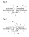
- another discharge limiting plate 33 extends parallel to the conductive plate 12, as shown in Fig. 4, and comprises a plate-form main body portion 33a which is connected to the stem pins 29.
- a discharge limiting opening 34 is formed by a protruding part 33b which enters the concave portion 16 from the main body portion 33a.
- This protruding part 33b is separated from a wall face 16b of the concave portion 16 and takes the form of a truncated cone extending along the wall face 16b in the tube axis G direction.
- the generation region of the arc ball S within the concave portion 16 can be restricted, thereby raising the generation density of the arc ball S in the discharge limiting opening 34 such that luminance is increased.
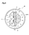
- another discharge limiting plate 35 extends parallel to the conductive plate 12 and comprises a plate-form main body portion 35a which is connected to the stem pins 29.
- a discharge limiting opening 36 is formed by a protruding part 35b which enters the concave portion 16 from the main body portion 35a. This protruding part 35b is separated from the wall face 16b of the concave portion 16 and takes a cylindrical form extending along the tube axis G.
- First electric power of approximately 10W is supplied to the cathode portion 20 from an external power source via the stem pins (not shown) for up to twenty seconds prior to discharge in order to preheat the coil portion of the cathode portion 20. Then a voltage of approximately 160V is applied between the cathode portion 20 and anode portion 8, thereby completing the preparation for arc discharge.
- a trigger voltage of approximately 350V is applied from an external power source to the focusing electrode portion 14 via the stem pins 18.
- the discharge limiting plate 30 is made of a ceramic, it is continuously maintained in a passive state. Hence discharge is successively generated between the cathode portion 20 and focusing electrode portion 14, and between the cathode portion 20 and anode portion 8.
- the discharge path is ensured by the employment of the discharge limiting opening 31, a starting discharge between the cathode portion 20 and anode portion 8 is reliably generated even when the discharge path is narrowed by the discharge limiting opening 17 having a diameter of 0.2mm, for example.
- arc discharge is maintained between the cathode portion 20 and anode portion 8 such that the arc ball S is generated within the concave portion 16.
- Ultraviolet light emitted from the arc ball S passes through the light exit window 4 as light of extremely high luminance and is discharged outside.
- the arc ball S can be continuously maintained in a compressed ball shape even when the lamp is illuminated due to the discharge limiting opening 31, and thus the arc ball S can be shaped with stability, thereby stabilizing the luminance and light quantity.
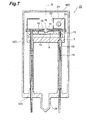
- a gas discharge tube 40 is a side-on type deuterium lamp.
- This discharge tube 40 is provided with a glass hermetically sealed container 42 into which deuterium gas is sealed at approximately several hundred Pa.
- the hermetically sealed container 42 is constituted by a cylindrical side tube 43 which seals one end side thereof and a stem (not shown) which seals the other end side of the side tube 43.
- a part of the side tube 43 is used as a light exit window 44.
- a light-emitting portion assembly 46 is housed inside the hermetically sealed container 42.
- the light-emitting portion assembly 46 comprises a base portion 47 made of an electrically insulating ceramic.
- An anode plate (anode portion) 48 is disposed in contact with the front face of the base portion 47, and the distal end part of a stem pin 49 disposed in a standing position in the stem so as to extend in the direction of the tube axis G is electrically connected to the back face of the anode plate 48.
- the light-emitting portion assembly 46 further comprises a focusing electrode support portion 50 made of an electrically insulating ceramic.
- This focusing electrode support portion 50 is fixed by being caused to contact the base portion 47 in a perpendicular direction to the tube axis G.
- the anode portion 48 is fixed by being gripped between the front face of the base portion 47 and the back face of the focusing electrode support portion 50.
- a conductive plate 52 is disposed in contact with the front face of the focusing electrode support portion 50.
- a focusing electrode portion 54 made of metal (for example molybdenum, tungsten, or an alloy thereof) is fixed by welding to the center of the conductive plate 52 in order to narrow the discharge path, and an arc ball shaping concave portion 56 is formed in this focusing electrode portion 54.
- the concave portion 56 houses an arc ball produced by discharge and is formed in a cup form widening toward the light exit window 44 so that light can be efficiently extracted.
- a discharge path narrowing opening 57 constituted by a small hole with a 0.2mm diameter is formed in the bottom face of the concave portion 56 such that a compressed ball shaped arc ball is formed within the concave portion 56, thereby increasing luminance.
- the conductive plate 52 is electrically connected to the distal end of a stem pin 55 which is disposed in a standing position in the stem, thus enabling electric power to be supplied from outside to the focusing electrode portion 54.
- a cathode portion 60 is disposed in the light-emitting portion assembly 46 in a position removed from the optical path on the light exit window 44 side, and this cathode portion 60 is electrically connected to a stem pin 59 disposed in a standing position in the stem via a connecting pin not shown in the drawing.
- Thermoelectrons are generated by the cathode portion 60, or more specifically, the cathode portion 60 comprises a tungsten coil portion which extends in the tube axis G direction and generates thermoelectrons.
- the cathode portion 60 is housed inside a cap-form metallic front cover 61.
- This front cover 61 is fixed by being bent following the insertion of a claw piece 61a provided thereon into a slit hole (not shown) provided in the focusing electrode support portion 50. Further, a rectangular light transmitting port 61b is formed in the front cover 61 at the part which opposes the light exit window 44.
- a discharge current plate 62 is provided inside the front cover 61 in a position removed from the optical path between the cathode portion 60 and focusing electrode portion 54.
- An electron-emitting window 62a of the discharge current plate 62 is formed as a rectangular opening for allowing the transmission of thermoelectrons.
- the discharge current plate 62 is fixed to the front face of a discharge limiting plate (discharge limiting portion) 70 to be described hereinafter which is fixed to the focusing electrode support portion 50.
- the light-emitting portion assembly 46 constituted in this manner is provided within the hermetically sealed container 42, and since the interior of the hermetically sealed container 42 must be filled with deuterium gas at several hundred Pa, a glass exhaust pipe (not shown) is formed integrally with the hermetically sealed container 42. This exhaust pipe is sealed by being fused at the end of the assembly process after the air inside the hermetically sealed container 42 has been removed and deuterium gas at a predetermined pressure has been appropriately filled therein.
- a discharge limiting plate 70 is separated from the conductive plate 52 in a perpendicular direction to the tube axis G.
- the discharge limiting plate 70 is fixed by beingbent following the insert ion of a clawpiece 70a thereof into a slit hole (not shown) provided in the focusing electrode support portion 50.
- the discharge limiting plate 70 is provided with a circular discharge limiting opening 71 formed opposite the concave portion 56. This discharge limiting opening 71 opposes the concave portion 56 in a perpendicular direction to the tube axis G.
- discharge limiting plate 70 functions similar to those of the aforementioned discharge limiting plate 30 in the first embodiment and therefore explanation thereof has been omitted. Since the operational principles of the side-on type deuterium lamp 40 are similar to those of the aforementioned head-on type deuterium lamp 1, explanation thereof has also been omitted.
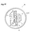
- a head-on type gas discharge tube 75 comprises a discharge limiting plate (discharge limiting portion) 76 made of an electrically insulating ceramic, and this discharge limiting plate 76 contacts the surface of a focusing electrode portion 14 and also contacts a focusing electrode support portion 10.
- the discharge limiting plate 76 can be seated with stability on the focusing electrode support portion 10.
- discharge limiting plate 76 is fixed to the distal ends of stem pins 29 disposed in a standing position in the stem 5 so as to pass through a base portion 7 and the focusing electrode support portion 10. The part of the stem pins 29 which protrudes from the stem 5 has been severed.
- the discharge limiting plate 76 is also provided with a circular discharge limiting opening 78 formed opposite a concave portion 16.
- This discharge limiting opening 78 is formed opposite the concave portion 16 in the tube axis G direction so as to narrow an opening part 16a of the concave portion 16 on the light exit window 4 side. If, for example, a diameter A of the opening part 16a of the concave portion 16 is 3.2mm, a diameter B of the discharge limiting opening 31 is preferably 1.5mm.
- the shaping space for the arc ball S on the cathode portion 20 side of the concave portion 16 is restricted by the discharge limiting opening 78 disposed in front of the concave portion 16, thus ensuring the formation of a discharge path from the cathode portion 20 to the concave portion 16 with the result that a starting discharge is reliably generated.
- the discharge limiting opening 78 also allows the arc ball S to be continuously maintained in a compressed ball shape even when the lamp is illuminated, and thus the arc ball S can be shaped with stability, thereby stabilizing the luminance and the light quantity.
- a head-on type gas discharge tube 80 comprises a discharge limiting plate (discharge limiting portion) 81 made of an electrically insulating ceramic, and this discharge limiting plate 81 contacts the surface of a focusing electrode portion 54 and also contacts a conductive plate 52.
- the discharge limiting plate 81 further comprises a circular discharge limiting opening 82 which opposes a concave portion 56 in a perpendicular direction to the tube axis G. Note that the functions of the discharge limiting plate 81 are similar to those of the aforementioned discharge limiting plate 76 of the third embodiment and therefore description thereof has been omitted.
- the present invention may be used in a gas discharge tube.
Landscapes
- Vessels And Coating Films For Discharge Lamps (AREA)
Abstract
Description
A discharge
Hence the shaping space for the arc ball S on the
Claims (4)
- A gas discharge tube which is caused to discharge a predetermined light toward the outside from a light exit window of a hermetically sealed container by sealing gas inside said hermetically sealed container and generating discharge between an anode portion and a cathode portion disposed within said hermetically sealed container, said gas discharge tube comprising:a focusing electrode portion which is connected to an external power source and comprises a focusing opening disposed between said anode portion and said cathode portion for narrowing a discharge path and an arc ball shaping concave portion which widens toward said light exit window; anda ceramic discharge limiting portion disposed between said focusing electrode portion and said cathode portion and comprising a discharge limiting opening formed opposite said concave portion.
- The gas discharge tube according to claim 1, wherein said discharge limiting opening is disposed opposite said concave portion in order to narrow an opening part of said concave portion on said light exit window side.
- The gas discharge tube according to claim 1, wherein said discharge limiting opening is formed by a cylindrical protruding part which enters said concave portion from a main body part of said discharge limiting portion.
- The gas discharge tube according to claim 1, wherein said discharge limiting opening is formed by a truncated cone-form protruding part which enters said concave portion from the main body part of said discharge limiting portion.
Applications Claiming Priority (3)
| Application Number | Priority Date | Filing Date | Title |
|---|---|---|---|
| JP2000348406 | 2000-11-15 | ||
| JP2000348406A JP4907760B2 (en) | 2000-11-15 | 2000-11-15 | Gas discharge tube |
| PCT/JP2001/009990 WO2002041358A1 (en) | 2000-11-15 | 2001-11-15 | Gas discharge tube |
Publications (3)
| Publication Number | Publication Date |
|---|---|
| EP1341209A1 true EP1341209A1 (en) | 2003-09-03 |
| EP1341209A4 EP1341209A4 (en) | 2007-03-14 |
| EP1341209B1 EP1341209B1 (en) | 2013-10-30 |
Family
ID=18822001
Family Applications (1)
| Application Number | Title | Priority Date | Filing Date |
|---|---|---|---|
| EP01982793.0A Expired - Lifetime EP1341209B1 (en) | 2000-11-15 | 2001-11-15 | Gas discharge tube |
Country Status (7)
| Country | Link |
|---|---|
| US (1) | US6870317B2 (en) |
| EP (1) | EP1341209B1 (en) |
| JP (1) | JP4907760B2 (en) |
| KR (1) | KR100827914B1 (en) |
| CN (1) | CN1258207C (en) |
| AU (2) | AU2002214293B2 (en) |
| WO (1) | WO2002041358A1 (en) |
Cited By (1)
| Publication number | Priority date | Publication date | Assignee | Title |
|---|---|---|---|---|
| EP1551054A4 (en) * | 2002-04-30 | 2010-01-13 | Hamamatsu Photonics Kk | Gas discharge tube |
Families Citing this family (13)
| Publication number | Priority date | Publication date | Assignee | Title |
|---|---|---|---|---|
| JP3965156B2 (en) * | 2001-09-28 | 2007-08-29 | 浜松ホトニクス株式会社 | Gas discharge tube |
| JP3984177B2 (en) | 2003-02-12 | 2007-10-03 | 浜松ホトニクス株式会社 | Gas discharge tube |
| JP3984179B2 (en) | 2003-02-20 | 2007-10-03 | 浜松ホトニクス株式会社 | Gas discharge tube |
| JP4969772B2 (en) * | 2004-08-10 | 2012-07-04 | 浜松ホトニクス株式会社 | Gas discharge tube |
| JP4907852B2 (en) | 2004-08-24 | 2012-04-04 | 浜松ホトニクス株式会社 | Gas discharge tube |
| JP4572796B2 (en) * | 2004-11-11 | 2010-11-04 | 株式会社デンソー | Discharge lamp lighting device |
| DE102006040613B3 (en) * | 2006-08-30 | 2007-11-29 | Heraeus Noblelight Gmbh | Translucent low pressure discharge hydrogen lamp for spectral analytical application, has metallic housing construction protecting discharge chamber in bulb filled with deuterium |
| DE102008062410A1 (en) | 2008-12-17 | 2010-07-01 | Heraeus Noblelight Gmbh | Cathode shielding in deuterium lamps |
| JP6121667B2 (en) * | 2012-08-22 | 2017-04-26 | 浜松ホトニクス株式会社 | Discharge lamp and light source device |
| CN103762143B (en) * | 2014-01-08 | 2016-01-06 | 深圳市槟城电子有限公司 | A kind of gas discharge tube |
| TWI590753B (en) * | 2016-11-02 | 2017-07-01 | 和碩聯合科技股份有限公司 | Pin protective cover and bi-directional optical sub-assemblies device using the same |
| KR102955126B1 (en) * | 2019-06-19 | 2026-04-21 | 본스인코오포레이티드 | Gas discharge tube with improved ratio of leak path length to gap dimensions |
| KR20220146543A (en) | 2020-02-27 | 2022-11-01 | 본스인코오포레이티드 | MOV-related devices and methods with modified edges |
Family Cites Families (21)
| Publication number | Priority date | Publication date | Assignee | Title |
|---|---|---|---|---|
| NL155127B (en) | 1967-08-25 | 1977-11-15 | Philips Nv | LOW PRESSURE GAS DISCHARGE LAMP FOR GENERATING RESONANCE RADIATION. |
| JPS54141780U (en) | 1978-03-27 | 1979-10-02 | ||
| JPS6053015B2 (en) | 1978-04-22 | 1985-11-22 | 製鉄化学工業株式会社 | 5-n-butyl-2-thiopicolinanilide and its manufacturing method |
| EP0146383B1 (en) * | 1983-12-20 | 1992-08-26 | Eev Limited | Apparatus for forming electron beams |
| JPH07120518B2 (en) * | 1989-11-20 | 1995-12-20 | 浜松ホトニクス株式会社 | Flash lamp |
| JPH04255662A (en) * | 1991-02-08 | 1992-09-10 | Hitachi Ltd | deuterium discharge tube |
| JPH05217550A (en) * | 1992-02-03 | 1993-08-27 | Hitachi Ltd | Deuterium lamp |
| JPH06310101A (en) * | 1993-04-21 | 1994-11-04 | Hitachi Ltd | Deuterium discharge tube |
| JP2740738B2 (en) * | 1994-05-31 | 1998-04-15 | 浜松ホトニクス株式会社 | Gas discharge tube |
| JP2784148B2 (en) * | 1994-08-31 | 1998-08-06 | 浜松ホトニクス株式会社 | Gas discharge tube |
| JP2740741B2 (en) * | 1994-08-31 | 1998-04-15 | 浜松ホトニクス株式会社 | Gas discharge tube |
| JP2769436B2 (en) * | 1994-08-31 | 1998-06-25 | 浜松ホトニクス株式会社 | Gas discharge tube and lighting device thereof |
| JP3361401B2 (en) * | 1995-02-17 | 2003-01-07 | 浜松ホトニクス株式会社 | Gas discharge tube |
| JP3361644B2 (en) * | 1995-02-17 | 2003-01-07 | 浜松ホトニクス株式会社 | Gas discharge tube |
| JP3361402B2 (en) * | 1995-03-01 | 2003-01-07 | 浜松ホトニクス株式会社 | Gas discharge tube |
| DE19628925B4 (en) | 1996-07-18 | 2004-07-01 | Heraeus Noblelight Gmbh | Discharge lamp with a filling that contains deuterium, hydrogen, mercury, a metal halide or noble gas |
| US6078132A (en) * | 1998-01-21 | 2000-06-20 | Imaging & Sensing Technology Corporation | Miniature deuterium arc lamp |
| JP2000173547A (en) * | 1998-12-09 | 2000-06-23 | Hamamatsu Photonics Kk | Gas discharge tube |
| JP4183840B2 (en) * | 1999-04-28 | 2008-11-19 | 浜松ホトニクス株式会社 | Portable light source device |
| JP4185212B2 (en) * | 1999-04-28 | 2008-11-26 | 浜松ホトニクス株式会社 | Portable light source device |
| JP4183841B2 (en) * | 1999-04-28 | 2008-11-19 | 浜松ホトニクス株式会社 | Portable light source device |
-
2000
- 2000-11-15 JP JP2000348406A patent/JP4907760B2/en not_active Expired - Lifetime
-
2001
- 2001-11-15 WO PCT/JP2001/009990 patent/WO2002041358A1/en not_active Ceased
- 2001-11-15 EP EP01982793.0A patent/EP1341209B1/en not_active Expired - Lifetime
- 2001-11-15 AU AU2002214293A patent/AU2002214293B2/en not_active Ceased
- 2001-11-15 AU AU1429302A patent/AU1429302A/en active Pending
- 2001-11-15 KR KR1020037006560A patent/KR100827914B1/en not_active Expired - Fee Related
- 2001-11-15 CN CNB01820483XA patent/CN1258207C/en not_active Expired - Lifetime
- 2001-11-15 US US10/416,698 patent/US6870317B2/en not_active Expired - Lifetime
Cited By (1)
| Publication number | Priority date | Publication date | Assignee | Title |
|---|---|---|---|---|
| EP1551054A4 (en) * | 2002-04-30 | 2010-01-13 | Hamamatsu Photonics Kk | Gas discharge tube |
Also Published As
| Publication number | Publication date |
|---|---|
| JP4907760B2 (en) | 2012-04-04 |
| WO2002041358A1 (en) | 2002-05-23 |
| KR20030045855A (en) | 2003-06-11 |
| CN1479939A (en) | 2004-03-03 |
| KR100827914B1 (en) | 2008-05-07 |
| CN1258207C (en) | 2006-05-31 |
| AU2002214293B2 (en) | 2006-02-02 |
| EP1341209A4 (en) | 2007-03-14 |
| US6870317B2 (en) | 2005-03-22 |
| JP2002151008A (en) | 2002-05-24 |
| US20040021419A1 (en) | 2004-02-05 |
| AU1429302A (en) | 2002-05-27 |
| EP1341209B1 (en) | 2013-10-30 |
Similar Documents
| Publication | Publication Date | Title |
|---|---|---|
| US6873107B2 (en) | Gas discharge tube having multiple stem pins | |
| US6870317B2 (en) | Gas discharge tube | |
| KR100922039B1 (en) | Gas discharge tube | |
| EP0685874A1 (en) | Gas discharge tube | |
| EP0700072A2 (en) | Lighting device for gas discharge tube | |
| US5210461A (en) | Arc discharge lamp containing mechanism for extinguishing arc at end-of-life | |
| CN102257596B (en) | Cathode shielding for deuterium lamps | |
| KR100912334B1 (en) | Gas discharge tube | |
| CN100495638C (en) | gas discharge tube | |
| US5276379A (en) | Arc discharge lamp having cementless base members | |
| WO1999034402A1 (en) | Electrode structure for electron emission, discharge lamp, and discharge lamp apparatus | |
| US7781975B2 (en) | Gas discharge tube having cathode cover made of ceramics | |
| CN100378898C (en) | gas discharge tube | |
| JP2002279935A (en) | Excimer radiator | |
| JPWO1999034404A1 (en) | gas discharge tube | |
| JP3479657B2 (en) | Manufacturing method of electrodeless fluorescent lamp | |
| US20080224614A1 (en) | Looped Frame Arc Tube Mounting Assembly for Metal Halide Lamp | |
| KR20250030891A (en) | Short arc type discharge lamp and method of manufacturing short arc type discharge lamp | |
| JPH0992214A (en) | High-pressure metal vapor discharge lamp and its lighting device and lighting device | |
| US20110044051A1 (en) | Conductive element and lamp using the same | |
| JPH1074490A (en) | Electrodeless discharge lamp | |
| JPH1092376A (en) | Electrode device for discharge tube | |
| WO2002019384A1 (en) | Hollow cathode lamp, atomic absorption analyzer, and atomic fluorescence analyzer | |
| JPH08250065A (en) | Ceramics discharge lamp, its lighting device, and lighting device |
Legal Events
| Date | Code | Title | Description |
|---|---|---|---|
| PUAI | Public reference made under article 153(3) epc to a published international application that has entered the european phase |
Free format text: ORIGINAL CODE: 0009012 |
|
| 17P | Request for examination filed |
Effective date: 20030522 |
|
| AK | Designated contracting states |
Kind code of ref document: A1 Designated state(s): AT BE CH CY DE DK ES FI FR GB GR IE IT LI LU MC NL PT SE TR |
|
| AX | Request for extension of the european patent |
Extension state: AL LT LV MK RO SI |
|
| RBV | Designated contracting states (corrected) |
Designated state(s): AT BE CH CY DE FR GB IT LI |
|
| A4 | Supplementary search report drawn up and despatched |
Effective date: 20070212 |
|
| 17Q | First examination report despatched |
Effective date: 20090507 |
|
| REG | Reference to a national code |
Ref country code: DE Ref legal event code: R079 Ref document number: 60148417 Country of ref document: DE Free format text: PREVIOUS MAIN CLASS: H01J0061680000 Ipc: H01J0061100000 |
|
| GRAP | Despatch of communication of intention to grant a patent |
Free format text: ORIGINAL CODE: EPIDOSNIGR1 |
|
| RIC1 | Information provided on ipc code assigned before grant |
Ipc: H01J 61/10 20060101AFI20130424BHEP Ipc: H01J 61/68 20060101ALI20130424BHEP |
|
| INTG | Intention to grant announced |
Effective date: 20130522 |
|
| RIN1 | Information on inventor provided before grant (corrected) |
Inventor name: KAWAI, KOJI Inventor name: MINAMIZAWA, TSUYOSHI Inventor name: ITO, YOSHINOBU |
|
| RBV | Designated contracting states (corrected) |
Designated state(s): DE FR GB IT |
|
| GRAS | Grant fee paid |
Free format text: ORIGINAL CODE: EPIDOSNIGR3 |
|
| GRAA | (expected) grant |
Free format text: ORIGINAL CODE: 0009210 |
|
| AK | Designated contracting states |
Kind code of ref document: B1 Designated state(s): DE FR GB IT |
|
| REG | Reference to a national code |
Ref country code: GB Ref legal event code: FG4D |
|
| REG | Reference to a national code |
Ref country code: DE Ref legal event code: R096 Ref document number: 60148417 Country of ref document: DE Effective date: 20131224 |
|
| REG | Reference to a national code |
Ref country code: DE Ref legal event code: R097 Ref document number: 60148417 Country of ref document: DE |
|
| PG25 | Lapsed in a contracting state [announced via postgrant information from national office to epo] |
Ref country code: IT Free format text: LAPSE BECAUSE OF FAILURE TO SUBMIT A TRANSLATION OF THE DESCRIPTION OR TO PAY THE FEE WITHIN THE PRESCRIBED TIME-LIMIT Effective date: 20131030 |
|
| PLBE | No opposition filed within time limit |
Free format text: ORIGINAL CODE: 0009261 |
|
| STAA | Information on the status of an ep patent application or granted ep patent |
Free format text: STATUS: NO OPPOSITION FILED WITHIN TIME LIMIT |
|
| 26N | No opposition filed |
Effective date: 20140731 |
|
| REG | Reference to a national code |
Ref country code: FR Ref legal event code: ST Effective date: 20140917 |
|
| REG | Reference to a national code |
Ref country code: DE Ref legal event code: R097 Ref document number: 60148417 Country of ref document: DE Effective date: 20140731 |
|
| PG25 | Lapsed in a contracting state [announced via postgrant information from national office to epo] |
Ref country code: FR Free format text: LAPSE BECAUSE OF NON-PAYMENT OF DUE FEES Effective date: 20131230 |
|
| PGFP | Annual fee paid to national office [announced via postgrant information from national office to epo] |
Ref country code: GB Payment date: 20171115 Year of fee payment: 17 |
|
| GBPC | Gb: european patent ceased through non-payment of renewal fee |
Effective date: 20181115 |
|
| PG25 | Lapsed in a contracting state [announced via postgrant information from national office to epo] |
Ref country code: GB Free format text: LAPSE BECAUSE OF NON-PAYMENT OF DUE FEES Effective date: 20181115 |
|
| PGFP | Annual fee paid to national office [announced via postgrant information from national office to epo] |
Ref country code: DE Payment date: 20201103 Year of fee payment: 20 |
|
| REG | Reference to a national code |
Ref country code: DE Ref legal event code: R071 Ref document number: 60148417 Country of ref document: DE |