EP1341165B1 - Objective optical element, optical pick-up apparatus, and optical information recording reproducing apparatus - Google Patents
Objective optical element, optical pick-up apparatus, and optical information recording reproducing apparatus Download PDFInfo
- Publication number
- EP1341165B1 EP1341165B1 EP03251003A EP03251003A EP1341165B1 EP 1341165 B1 EP1341165 B1 EP 1341165B1 EP 03251003 A EP03251003 A EP 03251003A EP 03251003 A EP03251003 A EP 03251003A EP 1341165 B1 EP1341165 B1 EP 1341165B1
- Authority
- EP
- European Patent Office
- Prior art keywords
- information recording
- optical element
- optical
- recording medium
- objective optical
- Prior art date
- Legal status (The legal status is an assumption and is not a legal conclusion. Google has not performed a legal analysis and makes no representation as to the accuracy of the status listed.)
- Expired - Lifetime
Links
- 230000003287 optical effect Effects 0.000 title claims description 329
- 230000004075 alteration Effects 0.000 claims description 44
- 230000004907 flux Effects 0.000 claims description 40
- 239000000758 substrate Substances 0.000 claims description 24
- 206010010071 Coma Diseases 0.000 claims description 13
- 230000002093 peripheral effect Effects 0.000 claims description 7
- 206010073261 Ovarian theca cell tumour Diseases 0.000 description 12
- 208000001644 thecoma Diseases 0.000 description 12
- 230000015572 biosynthetic process Effects 0.000 description 8
- 239000004065 semiconductor Substances 0.000 description 8
- 238000006073 displacement reaction Methods 0.000 description 6
- 238000001514 detection method Methods 0.000 description 5
- 201000009310 astigmatism Diseases 0.000 description 2
- 230000006866 deterioration Effects 0.000 description 2
- 230000000694 effects Effects 0.000 description 2
- 230000001678 irradiating effect Effects 0.000 description 2
- 150000001875 compounds Chemical class 0.000 description 1
- 230000001105 regulatory effect Effects 0.000 description 1
Images




Classifications
-
- G—PHYSICS
- G11—INFORMATION STORAGE
- G11B—INFORMATION STORAGE BASED ON RELATIVE MOVEMENT BETWEEN RECORD CARRIER AND TRANSDUCER
- G11B7/00—Recording or reproducing by optical means, e.g. recording using a thermal beam of optical radiation by modifying optical properties or the physical structure, reproducing using an optical beam at lower power by sensing optical properties; Record carriers therefor
- G11B7/12—Heads, e.g. forming of the optical beam spot or modulation of the optical beam
- G11B7/125—Optical beam sources therefor, e.g. laser control circuitry specially adapted for optical storage devices; Modulators, e.g. means for controlling the size or intensity of optical spots or optical traces
- G11B7/127—Lasers; Multiple laser arrays
- G11B7/1275—Two or more lasers having different wavelengths
-
- G—PHYSICS
- G02—OPTICS
- G02B—OPTICAL ELEMENTS, SYSTEMS OR APPARATUS
- G02B13/00—Optical objectives specially designed for the purposes specified below
-
- G—PHYSICS
- G11—INFORMATION STORAGE
- G11B—INFORMATION STORAGE BASED ON RELATIVE MOVEMENT BETWEEN RECORD CARRIER AND TRANSDUCER
- G11B7/00—Recording or reproducing by optical means, e.g. recording using a thermal beam of optical radiation by modifying optical properties or the physical structure, reproducing using an optical beam at lower power by sensing optical properties; Record carriers therefor
- G11B7/12—Heads, e.g. forming of the optical beam spot or modulation of the optical beam
- G11B7/135—Means for guiding the beam from the source to the record carrier or from the record carrier to the detector
- G11B7/1353—Diffractive elements, e.g. holograms or gratings
-
- G—PHYSICS
- G11—INFORMATION STORAGE
- G11B—INFORMATION STORAGE BASED ON RELATIVE MOVEMENT BETWEEN RECORD CARRIER AND TRANSDUCER
- G11B7/00—Recording or reproducing by optical means, e.g. recording using a thermal beam of optical radiation by modifying optical properties or the physical structure, reproducing using an optical beam at lower power by sensing optical properties; Record carriers therefor
- G11B7/12—Heads, e.g. forming of the optical beam spot or modulation of the optical beam
- G11B7/135—Means for guiding the beam from the source to the record carrier or from the record carrier to the detector
- G11B7/1372—Lenses
- G11B7/1374—Objective lenses
-
- G—PHYSICS
- G11—INFORMATION STORAGE
- G11B—INFORMATION STORAGE BASED ON RELATIVE MOVEMENT BETWEEN RECORD CARRIER AND TRANSDUCER
- G11B7/00—Recording or reproducing by optical means, e.g. recording using a thermal beam of optical radiation by modifying optical properties or the physical structure, reproducing using an optical beam at lower power by sensing optical properties; Record carriers therefor
- G11B7/12—Heads, e.g. forming of the optical beam spot or modulation of the optical beam
- G11B7/135—Means for guiding the beam from the source to the record carrier or from the record carrier to the detector
- G11B7/1392—Means for controlling the beam wavefront, e.g. for correction of aberration
- G11B7/13922—Means for controlling the beam wavefront, e.g. for correction of aberration passive
-
- G—PHYSICS
- G11—INFORMATION STORAGE
- G11B—INFORMATION STORAGE BASED ON RELATIVE MOVEMENT BETWEEN RECORD CARRIER AND TRANSDUCER
- G11B7/00—Recording or reproducing by optical means, e.g. recording using a thermal beam of optical radiation by modifying optical properties or the physical structure, reproducing using an optical beam at lower power by sensing optical properties; Record carriers therefor
- G11B2007/0003—Recording, reproducing or erasing systems characterised by the structure or type of the carrier
- G11B2007/0006—Recording, reproducing or erasing systems characterised by the structure or type of the carrier adapted for scanning different types of carrier, e.g. CD & DVD
Definitions
- the present invention relates to an objective optical element used for an optical pick-up apparatus by which the recording/reproducing of an optical information recording medium whose operating wavelength is different and transparent substrate thickness is different is conducted by one objective lens, and optical pick-up apparatus and optical information recording reproducing apparatus, and particularly to the objective optical element in which a light source portion which oscillates the different wavelength is used for the modularized light source (2-laser 1 package module), or used for an optical system in which the focal length of the objective lens is short and which is sensitive to the error factors, and in which the image height coma characteristic at the time when each optical information recording medium is used, is improved, and the optical pick-up apparatus using it, and the optical information recording reproducing apparatus.
- each transparent substrate thickness is different.
- the spherical aberration generated by the difference of this transparent substrate thickness is corrected by any means.
- DVD and CD because the required numerical aperture is different, any countermeasure is necessary also for this.
- the objective lens on which the diffractive structure is provided is developed.
- an objective lens for example, on the one side surface of the objective lens, the diffractive structure which is different at the inside or outside of the specific height h from the optical axis is provided, and in the inside region, the spherical aberration is corrected for each transparent substrate thickness, and in the outside region, the spherical aberration is corrected only for the DVD, and there is a diffractive structure in which the spherical aberration is not corrected for the CD, but is made flare.
- the objective lens is structured in this manner, on each of optical information recording media, the converging spot which is respectively required at the time of the recording or reproducing of the information can be adequately formed.
- the correction of the spherical aberration when the information is recorded or reproduced on both of DVD/CD can be comparatively easily conducted.
- the coma also exists other than the spherical aberration. In the case where the coma is large, when the light flux tilted to the optical axis is incident, by the inclination of the objective lens generated due to the assembling error, there is a possibility that the formation of the adequate spot on the optical information recording medium is obstructed.
- both of the spherical aberrations at the time when both of the DVD/CD are used can be reduced, but for the coma, there is a problem that the both can not be simultaneously corrected.
- the light source of the optical pick-up apparatus to attain the interchangeability of the DVD/CD a light source in which 2 semiconductor lasers called so-called “2-laser 1 package", are assembled on one substrate and are made as one unit, is well known.
- the recording or reproducing of the information is conducted for both of the DVD/CD
- the light source for the DVD is arranged on the optical axis of the objective lens
- the light source for the CD is arranged at the position dislocated from the optical axis without fail, and accordingly, in such a case, it can be said that it is preferable that the coma when the CD is used, is reduced as much as possible.
- US 6,118,594 discloses an objective optical element having means for correcting spherical aberration when two different recording media and two different light sources are used but does not consider off-axis characteristics, such as coma aberration, at all.
- the present invention is attained, and the object of the present invention is to provide an objective optical element for the optical pick-up apparatus by which the coma can be corrected with good balance, and the recording or reproducing of the information can be adequately conducted onto the different optical information.recording media, and the optical pick-up apparatus and the optical information recording reproducing apparatus.
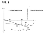
- Fig. 2 is a view in which the height from the optical axis is placed on the horizontal line (x), and the sine condition unsatisfied amount when the second optical information recording medium (for example, CD) is used, is placed on the vertical line (y), and which shows an example, in the common region and the exclusive region, in which the curve f2 showing the sine condition unsatisfied amount is found.
- the curve f2 is always negative, and the negative value is increased as the curve is separated from the optical axis.
- the curve f2 has an region R1 existing in the more positive side than the straight line (tangential line) at a further side from the optical axis than the first height x1.
- the curve f2 also has another region existing in the more negative side than the straight line d1.
- the curve f2 has an region R4 existing in the more positive side than the straight line (tangential line) d4.
- An objective optical element of the optical pick-up apparatus described in claim 2 can obtain the curve described relating to the invention described in claim 1 because, when the first optical information recording medium is used, the curve showing the sine condition unsatisfied amount in the common region, when the height from the optical axis is placed on the vertical line (x) and the sine condition unsatisfied amount when the second optical information recording medium is used, is placed on the horizontal line (y), and the second order differential value (d 2 y/dx 2 ) for the curve showing the relationship between the height from the optical axis and the sine condition unsatisfied amount is found, when the height from the optical axis of the ray of light passing the outmost peripheral portion of the common region is h 0 , when 0.5 h 0 ⁇ h ⁇ 0.8 h 0 , then d 2 ⁇ y / d ⁇ x 2 > 0.
- An objective optical element of the optical pick-up apparatus described in claim 3 is characterized in that: when the height from the optical axis is placed on the vertical line (x), and the sine condition unsatisfied amount when the first optical information recording medium is used, is placed on the horizontal line (y), and in the exclusive region, the differential value (dy/dx) for the curve showing the relationship between the height from the optical axis and the sine condition unsatisfied amount is found, when the straight line in which the differential value is an inclination at a certain height from the optical axis is drawn, at the further side from the optical axis than the certain height, the curve has an region existing in the more positive side than the straight line.
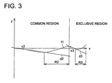
- Fig. 3 is a view showing an example in which the height from the optical axis is placed on the vertical line (x), and the sine condition unsatisfied amount when the first optical information recording medium is used, is placed on the horizontal line (y), and in the common region and the exclusive region, the curve f1 showing the sine condition unsatisfied amount is found.
- the curve f 1 has an region R2 existing in the more positive side than the straight line (tangential line) d2 at the further side than the certain height x2.
- x2 and the region R2 it has also another region existing in the more negative side than the straight line d2. Because it has such a characteristic, the same effect as the invention described in Item 5 can be obtained.
- An objective optical element of the optical pick-up apparatus described in claim 6 is characterized in that: in the case where the first optical information recording medium is used, when the height from the optical axis of the ray of light passing the outmost peripheral portion of the effective diameter of the objective optical element is hmax, the sine condition unsatisfied amount SC1 of the outmost peripheral ray of light satisfies SC ⁇ 1 hmax ⁇ 0.010 mm .
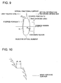
- Fig. 9 is a sectional view of the objective optical element (for example, objective lens) in which the step difference and the diffractive ring-shaped zone formed on the optical function surface of the optical information recording medium side are exaggeratedly shown.
- a step difference portion T2 which adjoins the common region and the exclusive region, and which is almost parallel to the optical axis and which.faces outside to the optical axis, is provided.
- the outside-axis coma when each optical information recording medium is used can be balanced.
- the step difference amount (dl, d2) of the step difference portion (T1, T2) is determined by the position of the mother aspheric surface, and the step difference amount of the difftactive structure provided on the mother aspheric surface.
- An objective optical element of the optical pick-up apparatus described in claim 7 is characterized in that: in the common region of the light source side in the objective optical element, the diffractive structure (D in Fig. 9) making the optical axis as the center of rotation is formed.
- An objective optical element of the optical pick-up apparatus described in claim 8 is characterized in that: when the first optical information recording medium and the second optical information recording medium are used, the image formation magnification by the objective optical element single body is infinite magnification.
- An objective optical element of the optical pick-up apparatus described in claim 9 is characterized in that: when the first optical information recording medium and the second optical information recording medium are used, the magnification m of the optical system from the light source to the optical information recording medium is respectively -1/5 ⁇ m ⁇ -1/10.
- the magnification m of the optical system from the light source to the optical information recording medium is respectively -1/5 ⁇ m ⁇ -1/10.
- An objective optical element of the optical pick-up apparatus described in claim 10 is characterized in that: when the first optical information recording medium is used, because the image formation magnification by the objective optical element single body is different from the image formation magnification by the objective optical element single body when the second optical information recording medium is used, for example, when the first optical information recording medium is used, the infinite light flux is incident on the objective optical element, and when the second optical information recording medium is used, the finite divergent light flux can be incident on the objective optical element, thereby, the difference of the working distance to dislocate the objective optical element in the optical axis direction can be reduced, and the optical pick-up apparatus can be compact, and the power saving can be intended.
- An objective optical element of the optical pick-up apparatus described in claim 11 is characterized in that: the light flux out-gone from the first light source is incident on the objective optical element as the infinite light flux, and the light flux out-gone from the second light source is incident on the objective optical element as the finite light flux.
- An objective optical element of the optical pick-up apparatus described in claim 12 can provide an objective optical element appropriate for the optical pick-up apparatus because the focal length f of the objective optical element is: 1.0 mm ⁇ f ⁇ 4.0 mm .
- An objective optical element of the optical pick-up apparatus described in claim 13 can provide an objective optical element appropriate for the optical pick-up apparatus because the focal length f of the objective optical element is: 1.5 mm ⁇ f ⁇ 3.5 mm , the transparent substrate thickness t1 of the first optical information recording medium is a half of the transparent substrate thickness t2 of the second optical information recording medium (2 x t1 ⁇ t2), and when the required numerical aperture when the first optical information recording medium is used, is NA1, and the required numerical aperture when the second optical information recording medium is used, is NA2, it satisfies: 0.59 ⁇ NA ⁇ 1 ⁇ 0.68 and 0.43 ⁇ NA ⁇ 2 ⁇ 0.58 the objective optical element appropriate for the interchangeable optical pick-up apparatus by which, for example, DVD or CD can be used, can be provided.
- An objective optical element of the optical pick-up apparatus described in claim 14 can provide an objective optical element in which the aberration characteristic is good because the respective coma in the angle of view 1° is suppressed under 0.05 ⁇ rms.
- An objective optical element of the optical pick-up apparatus described in claim 15 can solve or soften the problem of the coma due to the shift from the optical axis of any light source when it is used for the optical pick-up apparatus using the light source (for example, 2 laser 1 package module)in which the light source for the.first optical information recording medium and the light source for the second optical information recording medium are unitized.
- the light source for example, 2 laser 1 package module
- An optical pick-up apparatus described in claim 16 is an optical pick-up apparatus having: the first light source of the wavelength ⁇ 1 by which the recording or reproducing of the information is conducted by irradiating the light flux onto the first optical information recording medium whose transparent substrate thickness is t1; the second light source of the wavelength ⁇ 2 ( ⁇ 1 ⁇ ⁇ 2) by which the recording or reproducing of the information is conducted by irradiating the light flux onto the second optical information recording medium whose transparent substrate thickness is t2 (t1 ⁇ t2); and the light converging optical system including any one of the above objective optical elements by which the light fluxes out-gone from the first and the second light sources are converged onto the information recording surface through the transparent substrates of the first and the second optical information recording media.
- An optical information recording reproducing apparatus described in claim 17 is an optical information recording reproducing apparatus having the above optical pickup apparatus.
- a "diffractive structure" used in the present specification means a portion to which a relief is provided, and an action to converge or diverge the light flux by the diffraction is provided.
- the shape of the relief for example, on the surface of the objective lens, it is formed as a concentric circular ring-shaped zone around the optical axis, and when its cross section is viewed in the plane including the optical axis, it is well known that each ring-shaped zone has the saw-toothed shape, and it includes such a shape, and such a shape is specifically called the "diffraction ring-shaped zone".
- the objective lens means a lens having, in the narrow meaning, in the status that the optical information recording medium is loaded in the optical pick-up apparatus, at the position of the most optical information recording medium side, the light converging action which is positioned to oppose to it, and in the wide meaning, together with the lens, it means a lens group which can be moved at least in the optical axis direction by the actuator.
- a lens group means lenses at least more than one (for example, 2 lenses).
- the numerical aperture NA on the optical information recording medium side (image side) of the objective lens indicates the numerical aperture NA of the lens surface positioned on the most optical information recording medium side of the objective lens.
- the necessary numerical aperture NA means a numerical aperture regulated by standards of the respective optical information recording media, or it means, to respective optical information recording media, corresponding to the wavelength of the using light source, the numerical aperture of the objective lens of the diffraction limit performance by which a necessary spot diameter to record or reproduce the information can be obtained.
- the second optical information recording medium means an optical disk of each kind of CD-series, for example, CD-R, CD-RW, CD-Video, or CD-ROM
- the first optical information recording medium means an optical disk of each kind of DVD series such as DVD-POM, DVD-RAM, DVD-R, DVD-RW, or DVD-Video.
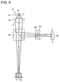
- Fig. 4 is an outline structural view of an optical information recording reproducing apparatus or optical pick-up apparatus (including the light source of the 2-laser 1 package module type), according to the present embodiment.
- the first semiconductor laser 111 as the first light source and the second semiconductor laser 112 as the second light source are attached onto the same substrate surface which is perpendicular to the optical axis, and structured as one unit.
- the light flux modulated and reflected by the information bit on the information recording surface 22 passes again the objective lens 16 and the stop 17, and incident on the beam splitter 120, and reflected here, and the astigmatism is given by the cylindrical lens 180, and incident on the photo detector 30 through the concave lens 50, and its output signal is used, and the reading-out signal of the information which is information-recorded onto the first optical disk 20 is obtained.
- the second dimensional actuator moves the objective lens 16 so that the light flux from the first semiconductor laser 111 is image formed onto the recording surface 22 of the of the first optical disk 20, and moves the objective lens 16 so that the light flux from the semiconductor laser 111 is image formed on the predetermined track.
- the light flux modulated and reflected on the information recording surface 22 by the information pit is reflected again by the objective lens 16, stop 17, and beam splitter 120, and the astigmatism is given by the cylindrical lens 180, and incident on the photo detector 30 through the concave lens 50, and using its output signal, the reading-out signal of the information recorded in the second optical disk 20 is obtained.
- the light amount change due to the shape change and the position change of the spot on the photo detector 30 is detected, and the focusing detection or track detection is conducted, and the objective lens 16 is moved by the second dimensional actuator (not shown) for the focusing and tracking.
- Fig. 4 an optical pick-up apparatus in which the diverging light flux is incident on the objective lens is shown, but in the following examples, a parallel light flux is incident on the objective lens when the DVD or CD is used. Accordingly, the surface interval between the 0-th surface abd the first surface is ⁇ . A case where a collimator lens exists between each of semiconductor lasers 111, 112, and the beam splitter 120, is presumed.
- Both surfaces of the objective lens are aspheric surfaces shown by [Expression 1].
- Z is the axis in the optical axis direction
- h is the height from the optical axis
- r is the paraxial radius of curvature
- ⁇ is the conical coefficient
- a 2i is the aspheric surface coefficient.
- the diffractive structure is integrally formed on the surface of the light source side aspheric surface of the objective lens.
- This diffractive structure is expressed by [Expression 3] as the unit is made mm by the optical path difference function ⁇ to the blazed wavelength ⁇ B.
- the paraxial power of the diffractive portion is expressed by this secondary coefficient. Further, by the coefficient other than secondary one, for example, 4-th, 6-th order coefficient, the spherical aberration can be controlled.
- spherical aberration is corrected as the total by providing the spherical aberration of the reversal characteristic at the diffraction portion, on the spherical aberration which the refractive portion has, or that, by operating the spherical aberration of the diffraction portion, the total spherical aberration is made to a desired flare amount.
- the spherical aberration at the time of temperature change can also be considered as the total of the temperature change of the spherical aberration of the refraction portion and the spherical aberration change of the diffraction portion.
- 2 optical function surfaces are formed on the surface of the light source side of the objective lens as the objective optical element.
- the inside optical function surface (common region) in which the spherical aberration when the DVD, and CD are respectively used, is corrected is formed, and on the optical function surface outside that, an exclusive region in which the light flux passing such a optical function surface when the spherical aberration is corrected when the DVD is used, and when the CD is used in the situation of a best focus, is the flare light on the optical information recording medium surface, is formed.
- Table 2 the lens data of the objective lens according to the present example is shown.
- the objective lens in the present example because the above-described design is conducted, even when the stop diameters are same in the DVD and CD, the required main spot diameter is obtained on the optical information recording medium surface. Relating to the coma value outside the CD axis, because the order of the distance of the main spot light and the flare light formed in the exclusive region is about 10 times of the spot diameter, the estimation is conducted on the light flux of only the common region.
- 2 optical function surfaces are formed on the surfaces of both of the light source side and the optical information recording medium side of the objective lens as the objective optical element.
- the inside optical function surface (common region) in which the spherical aberration when the DVD and CD are respectively used, is corrected is formed, and on the optical function surface outside that, the exclusive region in which the spherical aberration is corrected when the DVD is used, and when the CD is used in the best focus condition, the light flux passing such a optical function surface is the flare light on the optical information recording medium surface, is formed.
- a step difference portion as shown in Fig. 9, is provided between the common region and the exclusive region.
- Table 3 the lens data of the objective lens according to the present example is shown.
- a spherical aberration view and a view of the sine condition unsatisfied amount are respectively shown for the example 2.
- Unit of the horizontal line is mm.
- the objective lens design in which, while the deterioration of the DVD outside-axis coma is being suppressed, the CD outside-axis coma is improved, is conducted.
- the coma (COMA1) when the parallel light flux is incident at the angle of view 1° when the DVD is used is 0.006 ⁇ 1 rms
- the coma (COMA2) when the CD is used is 0.08 ⁇ 2 rms.
- the values defined in Claims are as follows in the example.
- SC1max 0.012 mm SC2max 0.015 mm SC1(hmax) -0.001 mm SC1(h 0 ) 0.012 mm SC1(h 0 /2) -0.001 mm SC2(h 0 ) -0.014 mm SC2(h 0 /2) -0.006 mm SC1 Dmin -0.002 mm SC1 smin -0.001 mm SC1 out (h) -0.001 mm d1 0.001 mm d2 0.002 mm h CDNA 1.589 mm
- 2 optical function surfaces are formed on the both surfaces of the light source side and optical information recording medium side of the objective lens as the objective optical element.
- Table 4 the lens data of the objective lens according to the present example is shown.
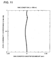
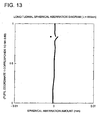
- FIGs. 11 and 12 views of the sine condition unsatisfied amount when the DVD and CD are used for the Example 3, are shown. Further, in Figs. 13 and 14, the spherical aberration views when the DVD and CD are used for the Example 3 are shown. Unit of the horizontal line is mm.
- the values defined in the Claims are as follows in the present example.
- 2 optical function surfaces are formed on the both surfaces of the light source side and optical information recording medium side of the objective lens as the objective optical element.
- Table 5 the lens data of the objective lens according to the present example is shown.
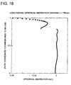
- FIGs. 15 and 16 views of the sine condition unsatisfied amount when the DVD and CD are used for the Example 4, are shown. Further, in Figs. 17 and 18, the spherical aberration views when the DVD and CD are used for the Example 4 are shown. Unit of the horizontal line is mm.
- the values defined in the Claims are as follows in the present example.
- the present invention is not limited to the above embodiments.
- the surface of the light source side of the objective lens is made a diffractive structure, it is not limited to that, and the diffractive structure may not also provided, and for example, it may be allowable when the sine condition unsatisfied amount of the DVD is set as the example.
- the light source is made 2-laser 1 package module light source, but, also for the discrete optical pick-up apparatus which is not modeled, its application is possible.
- the optical surface of the optical information recording medium side of the objective lens is structured by the same aspheric surface, it is not limited to this. On also this surface, 2 optical function surfaces are provided, and for respective exclusive region and the common region, the spherical aberration design and the sine condition unsatisfied amount design may be conducted.
- the sine condition unsatisfied amount in the design of the objective lens is described as above.
- the production error is generated at the time of the practical objective lens production, for example, when the surface shift of the objective lens is generated, the coma component is generated also for the axial light flux.
- the design to satisfy the requirement of the present invention is preferable.
- the order of the diffraction design is made a design to use the primary diffracted ray in the DVD, CD and the exclusive region and the common region together, but, it is not limited to this. Higher order of the diffraction order may also be used, or/and for the DVD and CD, the design to use the different order diffraction order light may be conducted.
- the objective optical element for the optical pick-up apparatus by which the coma can be corrected with good balance, and the recording or reproducing of the information can be adequately conducted onto the different optical information recording medium, and the optical pick-up apparatus and the optical information recording reproducing apparatus can be provided.
Landscapes
- Physics & Mathematics (AREA)
- Optics & Photonics (AREA)
- General Physics & Mathematics (AREA)
- Optical Head (AREA)
- Lenses (AREA)
- Optical Recording Or Reproduction (AREA)
Description
- The present invention relates to an objective optical element used for an optical pick-up apparatus by which the recording/reproducing of an optical information recording medium whose operating wavelength is different and transparent substrate thickness is different is conducted by one objective lens, and optical pick-up apparatus and optical information recording reproducing apparatus, and particularly to the objective optical element in which a light source portion which oscillates the different wavelength is used for the modularized light source (2-
laser 1 package module), or used for an optical system in which the focal length of the objective lens is short and which is sensitive to the error factors, and in which the image height coma characteristic at the time when each optical information recording medium is used, is improved, and the optical pick-up apparatus using it, and the optical information recording reproducing apparatus. - Nowadays, many kinds of optical information recording media exist, and the regulations for these optical information recording media are determined as shown in [Table 1]. In this connection, after this (the lens data in Table is included), it is defined that the exponent of 10 (for example, 2.5 x 10⁻³) is expressed by using E (for example, 2.5 x E-3).
Table 1 Optical disk Transparent substrate thickness (mm) Necessary numerical aperture NA (light source wavelength λ nm) CD, CD-R (reproducing) 1.20 0.45 (λ=780 nm) CD-R (recording, reproducing) 1.20 0.50 (λ=780 nm) DVD 0.60 0.60 (λ=635 nm) - Herein, as the media for which the interchangeability of mutual optical information recording media whose recording density is different is required, there are DVD and CD. In these optical information recording media, as shown in [Table 1], respectively, each transparent substrate thickness is different. In order to secure the interchangeability, it is necessary that the spherical aberration generated by the difference of this transparent substrate thickness is corrected by any means. Further, in DVD and CD, because the required numerical aperture is different, any countermeasure is necessary also for this.
- In order to realize the optical pick-up apparatus having the interchangeability of the DVD/CD, the objective lens on which the diffractive structure is provided, is developed. As such an objective lens, for example, on the one side surface of the objective lens, the diffractive structure which is different at the inside or outside of the specific height h from the optical axis is provided, and in the inside region, the spherical aberration is corrected for each transparent substrate thickness, and in the outside region, the spherical aberration is corrected only for the DVD, and there is a diffractive structure in which the spherical aberration is not corrected for the CD, but is made flare. When the objective lens is structured in this manner, on each of optical information recording media, the converging spot which is respectively required at the time of the recording or reproducing of the information can be adequately formed.
- In this connection, when such a diffractive structure is used for the objective lens, the correction of the spherical aberration when the information is recorded or reproduced on both of DVD/CD can be comparatively easily conducted. However, as the optical characteristic deterioration factor to obstacle the recording or reproducing of the adequate information, the coma also exists other than the spherical aberration. In the case where the coma is large, when the light flux tilted to the optical axis is incident, by the inclination of the objective lens generated due to the assembling error, there is a possibility that the formation of the adequate spot on the optical information recording medium is obstructed. However, when the above-described diffractive structure is used, both of the spherical aberrations at the time when both of the DVD/CD are used, can be reduced, but for the coma, there is a problem that the both can not be simultaneously corrected.
- Particularly, as the light source of the optical pick-up apparatus to attain the interchangeability of the DVD/CD, a light source in which 2 semiconductor lasers called so-called "2-
laser 1 package", are assembled on one substrate and are made as one unit, is well known. When such a light source is used, and the recording or reproducing of the information is conducted for both of the DVD/CD, for example, when the light source for the DVD is arranged on the optical axis of the objective lens, the light source for the CD is arranged at the position dislocated from the optical axis without fail, and accordingly, in such a case, it can be said that it is preferable that the coma when the CD is used, is reduced as much as possible. - US 6,118,594 discloses an objective optical element having means for correcting spherical aberration when two different recording media and two different light sources are used but does not consider off-axis characteristics, such as coma aberration, at all.
- In view of the above-described problems, the present invention is attained, and the object of the present invention is to provide an objective optical element for the optical pick-up apparatus by which the coma can be corrected with good balance, and the recording or reproducing of the information can be adequately conducted onto the different optical information.recording media, and the optical pick-up apparatus and the optical information recording reproducing apparatus.
- The invention is defined in the claims.
- Fig. 2 is a view in which the height from the optical axis is placed on the horizontal line (x), and the sine condition unsatisfied amount when the second optical information recording medium (for example, CD) is used, is placed on the vertical line (y), and which shows an example, in the common region and the exclusive region, in which the curve f2 showing the sine condition unsatisfied amount is found. Herein, the curve f2 is always negative, and the negative value is increased as the curve is separated from the optical axis. Further, at the first height x1, when the straight line d1 whose differential value is an inclination, is drawn (which means that the tangential line is drawn on the curve f2 at the first height x1), the curve f2 has an region R1 existing in the more positive side than the straight line (tangential line) at a further side from the optical axis than the first height x1. In this connection, between x1 and the.region R1, it also has another region existing in the more negative side than the straight line d1. According to such a characteristic, an effect in which the coma outside the optical axis can be balanced when each optical information recording medium is used, can be obtained.
- In this connection, at the fourth height x4, when the straight line whose differential value is an inclination (the tangential line drawn on the curve f2 at the fourth height x4) is drawn, at the nearer side from the optical axis than the first height x1, the curve f2 has an region R4 existing in the more positive side than the straight line (tangential line) d4.
- An objective optical element of the optical pick-up apparatus described in claim 2 can obtain the curve described relating to the invention described in
claim 1 because, when the first optical information recording medium is used, the curve showing the sine condition unsatisfied amount in the common region, when the height from the optical axis is placed on the vertical line (x) and the sine condition unsatisfied amount when the second optical information recording medium is used, is placed on the horizontal line (y), and the second order differential value (d2y/dx2) for the curve showing the relationship between the height from the optical axis and the sine condition unsatisfied amount is found, when the height from the optical axis of the ray of light passing the outmost peripheral portion of the common region is h0,
- An objective optical element of the optical pick-up apparatus described in claim 3 is characterized in that: when the height from the optical axis is placed on the vertical line (x), and the sine condition unsatisfied amount when the first optical information recording medium is used, is placed on the horizontal line (y), and in the exclusive region, the differential value (dy/dx) for the curve showing the relationship between the height from the optical axis and the sine condition unsatisfied amount is found, when the straight line in which the differential value is an inclination at a certain height from the optical axis is drawn, at the further side from the optical axis than the certain height, the curve has an region existing in the more positive side than the straight line.
- Fig. 3 is a view showing an example in which the height from the optical axis is placed on the vertical line (x), and the sine condition unsatisfied amount when the first optical information recording medium is used, is placed on the horizontal line (y), and in the common region and the exclusive region, the curve f1 showing the sine condition unsatisfied amount is found. Herein, at a certain height x2, when the straight line d2 in which the differential value is an inclination is drawn (which means that the tangential line is drawn on the curve f1 at a certain height x2), the curve f1 has an region R2 existing in the more positive side than the straight line (tangential line) d2 at the further side than the certain height x2. In this connection, between x2 and the region R2, it has also another region existing in the more negative side than the straight line d2. Because it has such a characteristic, the same effect as the invention described in Item 5 can be obtained.
- An objective optical element of the optical pick-up apparatus described in claim 4 is characterized in that: in the case where the infinite objective distance ray of light whose height from the optical axis is h, is out-gone from the objective optical element when the first optical information recording medium is used, when the angle formed between the ray of light after the outgoing and the optical axis is expressed by U, and the sine condition unsatisfied amount is defined as SC1 (h) = h/sin U - f (f: the focal length of the objective optical element when the first optical information recording medium is used), the sine condition unsatisfied amount in the exclusive region is monotonously increased as the height from the optical axis of the incident ray of light on the optical element is increased.
- An objective optical element of the optical pick-up apparatus described in claim 5 is characterized in that: in the case where the infinite objective distance ray of light whose height from the optical axis is h, is out-gone from the objective optical element, when the angle formed between the ray of light after the outgoing and the optical axis is expressed by U, and the sine condition unsatisfied amount is defined as SCl (h) = h/sin U - f (f: the focal length of the objective optical element when respective optical information recording media are used), when the maximum value of the sine condition unsatisfied amount absolute value in the common region when the first optical information recording medium is used, is SC1max and the maximum value of the sine condition unsatisfied amount absolute value in the.common region when the second optical information recording medium is used, is SC2max, it satisfies


- An objective optical element of the optical pick-up apparatus described in claim 6 is characterized in that: in the case where the first optical information recording medium is used, when the height from the optical axis of the ray of light passing the outmost peripheral portion of the effective diameter of the objective optical element is hmax, the sine condition unsatisfied amount SC1 of the outmost peripheral ray of light satisfies

- Fig. 9 is a sectional view of the objective optical element (for example, objective lens) in which the step difference and the diffractive ring-shaped zone formed on the optical function surface of the optical information recording medium side are exaggeratedly shown. As shown in Fig. 9, a step difference portion T2 which adjoins the common region and the exclusive region, and which is almost parallel to the optical axis and which.faces outside to the optical axis, is provided. When such a step difference portion is provided, as described relating to the invention described in
claim 1, the outside-axis coma when each optical information recording medium is used, can be balanced. In this connection, when the diffractive structure D is provided at least one side (in this example, the light source side) of the common region and the exclusive region, as shown in Fig. 10, the step difference amount (dl, d2) of the step difference portion (T1, T2) is determined by the position of the mother aspheric surface, and the step difference amount of the difftactive structure provided on the mother aspheric surface. - An objective optical element of the optical pick-up apparatus described in claim 7 is characterized in that: in the common region of the light source side in the objective optical element, the diffractive structure (D in Fig. 9) making the optical axis as the center of rotation is formed.
- An objective optical element of the optical pick-up apparatus described in claim 8 is characterized in that: when the first optical information recording medium and the second optical information recording medium are used, the image formation magnification by the objective optical element single body is infinite magnification.
- An objective optical element of the optical pick-up apparatus described in claim 9 is characterized in that: when the first optical information recording medium and the second optical information recording medium are used, the magnification m of the optical system from the light source to the optical information recording medium is respectively -1/5 ≦ m ≦ -1/10. When the value m is not smaller than the lower limit value, the position dislocation amount on the recording surface of each optical information recording medium to the position dislocation of the light source is not so large, and the error factor can be reduced, and when the value m is not larger than the upper limit value, the optical path length is not too long, and the optical pick-up apparatus can be compact.
- An objective optical element of the optical pick-up apparatus described in claim 10 is characterized in that: when the first optical information recording medium is used, because the image formation magnification by the objective optical element single body is different from the image formation magnification by the objective optical element single body when the second optical information recording medium is used, for example, when the first optical information recording medium is used, the infinite light flux is incident on the objective optical element, and when the second optical information recording medium is used, the finite divergent light flux can be incident on the objective optical element, thereby, the difference of the working distance to dislocate the objective optical element in the optical axis direction can be reduced, and the optical pick-up apparatus can be compact, and the power saving can be intended.
- An objective optical element of the optical pick-up apparatus described in claim 11 is characterized in that: the light flux out-gone from the first light source is incident on the objective optical element as the infinite light flux, and the light flux out-gone from the second light source is incident on the objective optical element as the finite light flux.
- An objective optical element of the optical pick-up apparatus described in claim 12 can provide an objective optical element appropriate for the optical pick-up apparatus because the focal length f of the objective optical element is:

- An objective optical element of the optical pick-up apparatus described in claim 13 can provide an objective optical element appropriate for the optical pick-up apparatus because the focal length f of the objective optical element is:


- An objective optical element of the optical pick-up apparatus described in claim 14 can provide an objective optical element in which the aberration characteristic is good because the respective coma in the angle of
view 1° is suppressed under 0.05 λ rms. - An objective optical element of the optical pick-up apparatus described in claim 15 can solve or soften the problem of the coma due to the shift from the optical axis of any light source when it is used for the optical pick-up apparatus using the light source (for example, 2
laser 1 package module)in which the light source for the.first optical information recording medium and the light source for the second optical information recording medium are unitized. - An optical pick-up apparatus described in
claim 16 is an optical pick-up apparatus having: the first light source of the wavelength λ1 by which the recording or reproducing of the information is conducted by irradiating the light flux onto the first optical information recording medium whose transparent substrate thickness is t1; the second light source of the wavelength λ2 (λ1 < λ2) by which the recording or reproducing of the information is conducted by irradiating the light flux onto the second optical information recording medium whose transparent substrate thickness is t2 (t1 < t2); and the light converging optical system including any one of the above objective optical elements by which the light fluxes out-gone from the first and the second light sources are converged onto the information recording surface through the transparent substrates of the first and the second optical information recording media. - An optical information recording reproducing apparatus described in
claim 17 is an optical information recording reproducing apparatus having the above optical pickup apparatus. - A "diffractive structure" used in the present specification means a portion to which a relief is provided, and an action to converge or diverge the light flux by the diffraction is provided. As the shape of the relief, for example, on the surface of the objective lens, it is formed as a concentric circular ring-shaped zone around the optical axis, and when its cross section is viewed in the plane including the optical axis, it is well known that each ring-shaped zone has the saw-toothed shape, and it includes such a shape, and such a shape is specifically called the "diffraction ring-shaped zone".
- In the present specification, the objective lens means a lens having, in the narrow meaning, in the status that the optical information recording medium is loaded in the optical pick-up apparatus, at the position of the most optical information recording medium side, the light converging action which is positioned to oppose to it, and in the wide meaning, together with the lens, it means a lens group which can be moved at least in the optical axis direction by the actuator. Herein, such a lens group means lenses at least more than one (for example, 2 lenses). Accordingly, in the present specification, the numerical aperture NA on the optical information recording medium side (image side) of the objective lens indicates the numerical aperture NA of the lens surface positioned on the most optical information recording medium side of the objective lens. Further, in the present specification, the necessary numerical aperture NA means a numerical aperture regulated by standards of the respective optical information recording media, or it means, to respective optical information recording media, corresponding to the wavelength of the using light source, the numerical aperture of the objective lens of the diffraction limit performance by which a necessary spot diameter to record or reproduce the information can be obtained.
- In the present specification, the second optical information recording medium means an optical disk of each kind of CD-series, for example, CD-R, CD-RW, CD-Video, or CD-ROM, and the first optical information recording medium means an optical disk of each kind of DVD series such as DVD-POM, DVD-RAM, DVD-R, DVD-RW, or DVD-Video. Furthermore, in the present specification, the "transparent substrate thickness t" includes t = 0.
- The invention will now be further described, by way of example only, by referring to the according drawings, in which:-
- Fig. 1 is a view for explaining the sine condition.
- Fig. 2 is a view for explaining the sine condition unsatisfied amount when the second optical information recording medium is used.
- Fig. 3 is a view for explaining the sine condition unsatisfied amount when the first optical information recording medium is used.
- Fig. 4 is a outline structural view of an optical information recording reproducing apparatus or an optical pick-up apparatus (including 2-
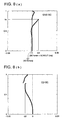
laser 1 package module type light source) according to the present embodiment. - Figs. 5(a) and 5(b) each is a view in which the spherical aberration view (shown by the longitudinal spherical aberration amount) according to an objective lens of the example 1 is respectively shown for the DVD (a) and CD (b).
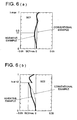
- Figs. 6(a) and 6(b) each is a view in which the sine condition unsatisfied amount according to an objective lens of the example 1 is respectively shown for the DVD (a) and CD (b).
- Figs. 7(a) and 7(b) each is a view in which the spherical aberration view (shown by the longitudinal spherical aberration amount) according to the objective lens of the example 2 is respectively shown for the DVD (a) and CD (b).
- Figs. 8(a) and 8(b) is a view in which the sine condition unsatisfied amount according to the objective lens of the example 2 is respectively shown for the DVD (a) and CD (b).
- Fig. 9 is a sectional view of the objective lens in which a step difference and a diffraction ring-shaped zone formed on an optical function surface of the optical information recording medium side are exaggeratedly shown.
- Fig. 10 is a view showing an example of a step difference amount (dl, d2) of the step difference portion (T1, T2) on the optical function surface.
- Fig. 11 is a view showing the sine condition unsatisfied amount according to the objective lens in Example 3 for the DVD.
- Fig. 12 is a view showing the sine condition unsatisfied amount according to the objective lens in Example 3 for the CD.
- Fig. 13 is a view showing the spherical aberration (shown by the longitudinal spherical aberration amount) according to the objective lens in Example 3 for the DVD.
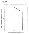
- Fig. 14 is a view showing the spherical aberration (shown by the longitudinal spherical aberration amount) according to the objective lens in Example 3 for the CD.
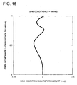
- Fig. 15 is a view showing the sine condition unsatisfied amount according to the objective lens in Example 4 for the DVD.
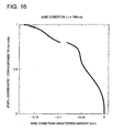
- Fig. 16 is a view showing the sine condition unsatisfied amount according to the objective lens in Example 4 for the CD.
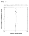
- Fig. 17 is a view showing the spherical aberration (shown by the longitudinal spherical aberration amount) according to the objective lens in Example 4 for the DVD.
- Fig. 18 is a view showing the spherical aberration (shown by the longitudinal spherical aberration amount) according to the objective lens in Example 4 for the CD.
- Referring to the drawings, the present invention will be more detailed below. Fig. 4, is an outline structural view of an optical information recording reproducing apparatus or optical pick-up apparatus (including the light source of the 2-
laser 1 package module type), according to the present embodiment. In Fig. 4, thefirst semiconductor laser 111 as the first light source and thesecond semiconductor laser 112 as the second light source are attached onto the same substrate surface which is perpendicular to the optical axis, and structured as one unit. The beam out-gone from the first semiconductor laser 111 (the wavelength λ1 = 610 nm - 670 nm) transmits thebeam splitter 120 and stopped by thestop 17, and converged onto theinformation recording surface 22 through thetransparent substrate 21 of the firstoptical disk 20 by theobjective lens 16. - The light flux modulated and reflected by the information bit on the
information recording surface 22 passes again theobjective lens 16 and thestop 17, and incident on thebeam splitter 120, and reflected here, and the astigmatism is given by thecylindrical lens 180, and incident on thephoto detector 30 through theconcave lens 50, and its output signal is used, and the reading-out signal of the information which is information-recorded onto the firstoptical disk 20 is obtained. - Further, the light amount change due to the shape change and position change of the spot on the
photo detector 30 is detected, and the focusing detection or track detection is conducted. According to this detection, the second dimensional actuator (not shown) moves theobjective lens 16 so that the light flux from thefirst semiconductor laser 111 is image formed onto therecording surface 22 of the of the firstoptical disk 20, and moves theobjective lens 16 so that the light flux from thesemiconductor laser 111 is image formed on the predetermined track. - The beam out-gone from the second semiconductor laser 112 (there wavelength λ1 = 740 nm - 870 nm) transmits the
beam splitter 120 which is a light wave compound means, and further, through thestop 17 and theobjective lens 16, is converged onto theinformation recording surface 22 through thetransparent substrate 21 of the secondoptical disk 20. - Then, the light flux modulated and reflected on the
information recording surface 22 by the information pit, is reflected again by theobjective lens 16, stop 17, andbeam splitter 120, and the astigmatism is given by thecylindrical lens 180, and incident on thephoto detector 30 through theconcave lens 50, and using its output signal, the reading-out signal of the information recorded in the secondoptical disk 20 is obtained. - Further, the light amount change due to the shape change and the position change of the spot on the
photo detector 30 is detected, and the focusing detection or track detection is conducted, and theobjective lens 16 is moved by the second dimensional actuator (not shown) for the focusing and tracking. - In this connection, in Fig. 4, an optical pick-up apparatus in which the diverging light flux is incident on the objective lens is shown, but in the following examples, a parallel light flux is incident on the objective lens when the DVD or CD is used. Accordingly, the surface interval between the 0-th surface abd the first surface is ∞. A case where a collimator lens exists between each of
semiconductor lasers beam splitter 120, is presumed. - A preferred example of the above-described embodiment will be described below. Both surfaces of the objective lens are aspheric surfaces shown by [Expression 1]. Where, Z is the axis in the optical axis direction, h is the height from the optical axis, r is the paraxial radius of curvature, κ is the conical coefficient, and A2i is the aspheric surface coefficient.

- Further, the local curvature R(h) used in the present specification is defined by [Expression 2].

- Further, the diffractive structure is integrally formed on the surface of the light source side aspheric surface of the objective lens. This diffractive structure is expressed by [Expression 3] as the unit is made mm by the optical path difference function Φ to the blazed wavelength λB. The paraxial power of the diffractive portion is expressed by this secondary coefficient. Further, by the coefficient other than secondary one, for example, 4-th, 6-th order coefficient, the spherical aberration can be controlled. Herein, "can be controlled" means that the spherical aberration is corrected as the total by providing the spherical aberration of the reversal characteristic at the diffraction portion, on the spherical aberration which the refractive portion has, or that, by operating the spherical aberration of the diffraction portion, the total spherical aberration is made to a desired flare amount. In this case, the spherical aberration at the time of temperature change can also be considered as the total of the temperature change of the spherical aberration of the refraction portion and the spherical aberration change of the diffraction portion.

- In the present example, 2 optical function surfaces are formed on the surface of the light source side of the objective lens as the objective optical element. On the optical function surface including the optical axis, the inside optical function surface (common region) in which the spherical aberration when the DVD, and CD are respectively used, is corrected, is formed, and on the optical function surface outside that, an exclusive region in which the light flux passing such a optical function surface when the spherical aberration is corrected when the DVD is used, and when the CD is used in the situation of a best focus, is the flare light on the optical information recording medium surface, is formed. In Table 2, the lens data of the objective lens according to the present example is shown.
Table 2 f1=3.05mm f2=3.07mm NA1:0.60 NA2:0.47 The i-th surface ri di (655nm) ni (655nm) di (785nm) ni (785nm) 0 ∞ ∞ 1 ∞ 0.0 1.0 0.0 1.0 Stop diameter Φ3.660mm 2 1.87178 1.72000 1.52915 1.72000 1.52541 2' 1.92357 1.72000 1.52915 1.72000 1.52541 3 -7.98941 1.69938 1.0 1.33477 1.0 4 ∞ 0.6 1.57752 1.2 1.57063 5 ∞
The second surface (0<h<1.419 mm: DVD/CD common region)
Aspheric surface coefficientκ -1.0230 x E-0 A1 +5.7970 x E-3 P1 4.0 A2 -4.8819 x E-4 P2 6.0 A3 +1.1480 x E-3 P3 8.0 A4 -4.3700 x E-4 P4 10.0 A5 +7.8504 x E-5 P5 12.0 A8 -1.4534 x E-5 P6 14.0 C4 -2.0201 x E-0 C6 -8.9539 x E-1 C8 +3.8143 x E-1 C10 -8.1400 x E-2
Aspheric surface coefficientκ -3.2868 x E-1 A1 -3.7854 x E-3 P1 4.0 A2 +1.1888 x E-4 P2 6.0 A3 +2.2964 x E-4 P3 8.0 A4 -1.3557 x E-4 P4 10.0 A5 -8.0336 x E-5 P5 12.0 A6 +1.8473 x E-5 P6 14.0 C2 -1.0061 x E+1 C4 +6.3493 x E-0 C6 -2.1340 x E-0 C8 -8.3911 x E-2 C10 +7.1252 x E-2 κ +8.4421 x E+0 A1 +1.0492 x E-2 P1 4.0 A2 +7.9177 x E-3 P2 6.0 A3 -4.8995 x E-3 P3 8.0 A4 +2.2015 x E-4 P4 10.0 A5 +3.4801 x E-4 P5 12.0 A6 -5.6907 x E-5 P6 14.0 - In this connection, in the objective lens in the present example, because the above-described design is conducted, even when the stop diameters are same in the DVD and CD, the required main spot diameter is obtained on the optical information recording medium surface. Relating to the coma value outside the CD axis, because the order of the distance of the main spot light and the flare light formed in the exclusive region is about 10 times of the spot diameter, the estimation is conducted on the light flux of only the common region.
- In this manner, in the situation that both of the sine condition unsatisfied amount at the time of the transparent substrate thickness can not be made zero in principle, the design in which the respective comas outside axis of DVD/CD are balanced, can be attained. As in Fig. 6, when the eye is put on the CD sine condition unsatisfied amount design, although in the common region, the sine condition unsatisfied amount of the present example is generally larger than the conventional example, its curve design itself is controlled, the outside-axis coma can be more reduced than the conventional example as a result. In the present example, although it is not the purpose that the sine condition unsatisfied amount in the DVD is made zero perfectly, the DVD outside-axis coma as a result can also be suppressed in the level of no problem practically. In this connection, in Fig. 6, h, h1, h2, and hmax correspond to the signs used in Claims. Further, values defined in Items are as follows in Examples.
SC1max 0.006 mm SC2max 0.024 mm SC1(hmax) 0.007 mm SC1(h0) 0.004 mm SC1(h0/2) -0.006 mm SC2(h0) -0.024 mm SC2(h0/2) -0.012 mm - In the present example, 2 optical function surfaces are formed on the surfaces of both of the light source side and the optical information recording medium side of the objective lens as the objective optical element. On the optical function surface including the optical axis, the inside optical function surface (common region) in which the spherical aberration when the DVD and CD are respectively used, is corrected, is formed, and on the optical function surface outside that, the exclusive region in which the spherical aberration is corrected when the DVD is used, and when the CD is used in the best focus condition, the light flux passing such a optical function surface is the flare light on the optical information recording medium surface, is formed. Further, between the common region and the exclusive region, a step difference portion as shown in Fig. 9, is provided. In Table 3, the lens data of the objective lens according to the present example is shown.
Table 3 f1=3.36 mm, f2=3.38 mm NA1:0.60 NA2:0.47 The i-th surface ri di (655nm) ni (655nm) di (788nm) ni (788nm) 0 ∞ ∞ 1 ∞ 0.0 1.0 0.0 1.0 Stop diameter Φ4.032mm 2 2.08078 2.20000 1.52915 2.20000 1.52534 2' 2.00570 0.00091 1.52915 0.00091 1.52534 3 -7.74668 1.75045 1.0 1.33797 1.0 3' -7.75528 0.00156 1.0 0.00156 1.0 4 ∞ 0.6 1.57752 1.2 1.57051 5 ∞ *di shows the displacement from the i-th surface to the (i+1)-th surface.
*d2', d3' respectively show the displacement from the 2nd surface, 3rd surface to the 2'nd surface, and the 3'rd surface.
The 2nd surface (0<h<1.589 mm: DVD/CD common region)
Aspheric surface coefficientκ -2.3679 x E-0 A1 +2.4225 x E-2 P1 4.0 A2 -3.2907 x E-3 P2 6.0 A3 +5.8739 x E-4 P3 8.0 A4 -3.2231 x E-5 P4 10.0 C4 -2.0201 x E-0 C6 -8.9539 x E-1 C8 +3.8143 x E-1 C10 -8.1400 x E-2
Apheric surface coefficientκ -8.5949 x E-1 A1 -5.4305 x E-3 P1 4.0 A2 +4.4524 x E-4 P2 6.0 A3 +1.1271 x E-3 P3 8.0 A4 -2.4275 x E-4 P4 10.0 A5 -4.0506 x E-6 P5 12.0 A6 +3.2614 x E-6 P6 14.0 C2 -1.0061 x E+1 C4 +6.3493 x E-0 C6 -2.1340 x E-0 C8 -8.3911 x E-2 C10 +7.1252 x E-2
Aspheric surfaceκ +1.5681 x E+1 A1 +2.0648 x E-2 P1 4.0 A2 -9.4490 x E-3 P2 6.0 A3 +9.7699 x E-3 P3 8.0 A4 -3.6532 x E-3 P4 10.0 A5 -2.8584 x E-4 P5 12.0 A6 +3.6042 x E-4 P6 14.0
Aspheric surfaceκ +9.7980 x E+0 A1 +1.4045 x E-2 P1 4.0 A2 -2.0311 x E-3 P2 6.0 A3 +2.0822 x E-3 P3 8.0 A4 -1.3361 x E-3 P4 10.0 A5 +3.6669 x E-4 P5 12.0 A6 -3.6902 x E-5 P6 14.0 - In Fig. 7 and Fig. 8, a spherical aberration view and a view of the sine condition unsatisfied amount are respectively shown for the example 2. Unit of the horizontal line is mm.
- In the present example, the objective lens design in which, while the deterioration of the DVD outside-axis coma is being suppressed, the CD outside-axis coma is improved, is conducted. In the present example, the sine condition unsatisfied amount which satisfies this requirement and is shown in Fig. 8, is found. As the result, it can be performed that the coma (COMA1) when the parallel light flux is incident at the angle of
view 1° when the DVD is used, is 0.006 λ1 rms, and the coma (COMA2) when the CD is used, is 0.08 λ2 rms. In this connection, the values defined in Claims are as follows in the example.SC1max 0.012 mm SC2max 0.015 mm SC1(hmax) -0.001 mm SC1(h0) 0.012 mm SC1(h0/2) -0.001 mm SC2(h0) -0.014 mm SC2(h0/2) -0.006 mm SC1Dmin -0.002 mm SC1smin -0.001 mm SC1out (h) -0.001 mm d1 0.001 mm d2 0.002 mm hCDNA 1.589 mm - In the present example, 2 optical function surfaces are formed on the both surfaces of the light source side and optical information recording medium side of the objective lens as the objective optical element. On the optical function surface including the optical axis, the inside optical function surface (common region) in which the spherical aberration when the DVD (light source wavelength 655 nm)and CD (light source wavelength 785 nm) are respectively used, is corrected, is formed, and on the optical function surface outside that, the exclusive region in which the light flux whose spherical aberration is corrected when the DVD is used, and which passes such a optical function surface when the CD is used at the best focus condition, is a flare light on the optical information recording medium surface, is formed. In Table 4, the lens data of the objective lens according to the present example is shown.
Table 4 Example 3 lens data f1=1.80 mm, f2=1.81 mm NA1:0.60 NA2:0.47 The i-th surface ri di (655nm) ni (655nm) di (780nm) ni (780nm) 0 ∞ 29.33910 1 ∞ 0.0 1.0 0.0 1.0 stop diameter Φ2.160mm 2 1.12922 0.92000 1.54094 0.92000 1.53728 2' 1.25557 0.00860 1.54094 0.00860 1.53728 3 -5.04774 0.90505 1.0 0.65069 1.0 3' -3.93413 0.00000 1.0 0.00000 1.0 4 ∞ 0.6 1.57752 1.2 1.57084 5 ∞ *di shows the displacement from the i-th surface to the (i+1)-th surface.
*d2', d3' respectively show the displacement from the 2nd surface, 3rd surface to the 2'nd surface, and the 3'rd surface.
The 2nd surface (0 ≦ h ≦ 0.900 mm: DVD/CD common region)
Aspheric surface coefficientκ -1.4625 x E-0 A1 +7.6022 x E-2 P1 4.0 A2 -2.1865 x E-2 P2 6.0 A3 +6.0304 x E-2 P3 8.0 A4 -9.9892 x E-2 P4 10.0 A5 +1.1041 x E-1 P5 12.0 A6 -4.7810 x E-2 P6 14.0 C4 -7.9189 x E-1 C6 -1.4005 x E+1 C8 +6.8812 x E-0
Aspheric surface coefficientκ -1.0150 x E-0 A1 +1.0375 x E-1 P1 4.0 A2 -1.7430 x E-2 P2 6.0 A3 -1.2551 x E-2 P3 8.0 A4 +1.4297 x E-3 P4 10.0 A5 +9.8299 x E-3 P5 12.0 A6 -8.3141 x E-3 P6 14.0 C2 +7.2457 x E-1 C4 -2.6654 x E-0 C6 -4.7087 x E-0 C8 -1.0307 x E-0 C10 -2.5585 x E-0
Aspheric surface coefficientκ -2.9759 x E+1 A1 +7.3798 x E-3 P1 4.0 A2 +5.6739 x E-2 P2 6.0 A3 -3.8042 x E-2 P3 8.0 A4 -4.5903 x E-2 P4 10.0 A5 +1.0494 x E-1 P5 12.0 A6 -7.5467 x E-2 P6 14.0
Aspheric surface coefficientκ -9.6145 x E+1 A1 +2.7265 x E-2 P1 4.0 A2 -4.0614 x E-2 P2 6.0 A3 +7.7366 X E-2 P3 8.0 A4 -9.7942 x E-2 P4 10.0 A5 +5.4540 x E-2 P5 12.0 A8 -1.2174 x E-2 P6 14.0 - In Figs. 11 and 12, views of the sine condition unsatisfied amount when the DVD and CD are used for the Example 3, are shown. Further, in Figs. 13 and 14, the spherical aberration views when the DVD and CD are used for the Example 3 are shown. Unit of the horizontal line is mm.
- In the present example, when the DVD is used, the infinite light flux is made incident on the objective lens, and when the CD is used, the diverging finite light flux is made incident on the objective lens. The image formation magnification of the objective lens when the DVD is used, is the infinite magnification, and the image formation magnification of the objective lens when the CD is used, is m = -1/15.3. In this connection, the values defined in the Claims are as follows in the present example.
SC1max 0.005 SC2max 0.053 SC1(hmax) -0.001 SC1(h0) 0.001 SC1(h0/2) -0.0.04 SC2(h0) -0.053 SC2(h0/2) -0.014 - In the present example, 2 optical function surfaces are formed on the both surfaces of the light source side and optical information recording medium side of the objective lens as the objective optical element. On the optical function surface including the optical axis, the inside optical function surface (common region) in which the spherical aberration when the DVD (light source wavelength 660 nm)and CD (light source wavelength 788 nm) are respectively used, is corrected, is formed, and on the optical function surface outside that, the exclusive region in which the light flux whose spherical aberration is corrected when the DVD is used, and which passes such a optical function surface when the CD is used at the best focus condition, is a flare light on the optical information recording medium surface, is formed. In Table 5, the lens data of the objective lens according to the present example is shown.
Table 5 Example 4 lens data f1=2.16mm f2=2.18mm NA1:0.65 NA2:0.5 The i-th surface ri di(660nm) ni (660nm) di (788nm) ni (788nm) 0 ∞ 30.7823 1 ∞ 0.0 1.0 0.0 1.0 stop diameter Φ2.808mm 2 1.33057 1.16000 1.53596 1.16000 1.53589 2' 1.33116 0.01372 1.53596 0.01372 1.53589 3 -5.96662 1.12894 1.0 0.93002 1.0 3' -16.80174 -0.03217 1.0 -0.03217 1.0 4 ∞ 0.6 1.57718 1.2 1.57051 5 ∞ *di shows the displacement from the i-th surface to the (i+1)-th surface.
*d2', d3' respectively show the displacement from the 2nd surface, 3rd surface to the 2'nd surface, and the 3'rd surface.
The 2nd surface (0 ≦ h ≦ 1.147 mm: DVD/CD common region)
Aspheric surface coefficientκ -1.2356 x E-0 A1 +4.8835 x E-2 P1 4.0 A2 -1.7069 x E-2 P2 6.0 A3 -4.5749 x E-3 P3 8.0 A4 +1.1331 x E-3 P4 10.0 A5 +1.5861 x E-2 P5 12.0 A6 -6.8124 x E-3 P6 14.0 C2 +4.3478 x E-0 C4 +8.5468 x E-0 C6 +7.4019 x E-1 C8 -1.8501 x E+1 C10 +1.0207 x E+1
Aspheric surface coefficientκ -7.0331 x E-0 A1 +1.7943 x E-1 P1 4.0 A2 -5.3203 x E-2 P2 6.0 A3 -4.5553 x E-2 P3 8.0 A4 -3.2013 x E-2 P4 10.0 A5 -8.0925 x E-3 P5 12.0 A6 -4.6611 x E-4 P6 14.0 C2 +3.2205 x E+1 C4 -3.3148 x E+1 C6 +1.8655 x E-0 C8 +1.1896 x E+1 C10 -4.2826 x E-0
Aspheric surface coefficientκ -1.5000 x E+2 A1 -5.0506 x E-2 P1 4.0 A2 +5.7588 x E-3 P2 6.0 A3 +1.0083 x E-1 P3 8.0 A4 -3.5644 x E-2 P4 10.0 A5 -5.5537 x E-2 P5 12.0 A6 +2.5224 x E-2 P6 14.0 A7 +3.8507 x E-3 P7 16.0 A8 -1.8149 x E-3 P8 18.0
Aspheric surface coefficientκ -6.1189 x E+1 A1 +2.4455 x E-2 P1 4.0 A2 -4.0956 x E-2 P2 6.0 A3 +3.0991 x E-2 P3 8.0 A4 -2.0461 x E-2 P4 10.0 A5 +9.1913 x E-3 P5 12.0 A6 -1.7370 x E-3 P6 14.0 A7 +7.1453 x E-5 P7 16.0 - In Figs. 15 and 16, views of the sine condition unsatisfied amount when the DVD and CD are used for the Example 4, are shown. Further, in Figs. 17 and 18, the spherical aberration views when the DVD and CD are used for the Example 4 are shown. Unit of the horizontal line is mm.
- In the present example, when the DVD is used, the infinite light flux is made incident on the objective lens, and when the CD is used, the diverging finite light flux is made incident on the objective lens. The image formation magnification of the objective lens when the DVD is used, is the infinite magnification, and the image formation magnification of the objective lens when the CD is used, is m = -1/13.2. In this connection, the values defined in the Claims are as follows in the present example.
SC1max 0.016 SC2max 0.080 SC1(hmax) 0.001 SC1(h0) -0.003 SC1(h0/2) -0.011 SC2(h0) -0.080 SC2(h0/2) -0.026 - In this connection, the present invention is not limited to the above embodiments. Although the surface of the light source side of the objective lens is made a diffractive structure, it is not limited to that, and the diffractive structure may not also provided, and for example, it may be allowable when the sine condition unsatisfied amount of the DVD is set as the example. Further, the light source is made 2-
laser 1 package module light source, but, also for the discrete optical pick-up apparatus which is not modeled, its application is possible. Further, although the optical surface of the optical information recording medium side of the objective lens is structured by the same aspheric surface, it is not limited to this. On also this surface, 2 optical function surfaces are provided, and for respective exclusive region and the common region, the spherical aberration design and the sine condition unsatisfied amount design may be conducted. - The sine condition unsatisfied amount in the design of the objective lens is described as above. In contrast to this, because the production error is generated at the time of the practical objective lens production, for example, when the surface shift of the objective lens is generated, the coma component is generated also for the axial light flux. Also in this case, in the meaning of the balance design of the outside-axis coma, it is needless to say that the design to satisfy the requirement of the present invention is preferable. Further, the order of the diffraction design is made a design to use the primary diffracted ray in the DVD, CD and the exclusive region and the common region together, but, it is not limited to this. Higher order of the diffraction order may also be used, or/and for the DVD and CD, the design to use the different order diffraction order light may be conducted.
- According to the present invention, the objective optical element for the optical pick-up apparatus by which the coma can be corrected with good balance, and the recording or reproducing of the information can be adequately conducted onto the different optical information recording medium, and the optical pick-up apparatus and the optical information recording reproducing apparatus can be provided.
Claims (17)
- An objective optical element for use in an optical pickup apparatus which comprises a first light source (111) to emit a light flux having a wavelength λ1 for conducting recording or reproducing information for a first information recording medium (20) with a transparent substrate (21) having a thickness t1, a second light source (112) to emit a light flux having a wavelength λ2 (λ1 < λ2) for conducting recording or reproducing information for a second information recording medium (20) with a transparent substrate (21) having a thickness t2 (t1 < t2), and a light converging system (16) including the objective optical element to converge the light flux emitted from the first and second light sources onto an information recording plane (22) through the respective transparent substrates (21) of the first and second information recording media (20), the objective optical element comprising:an objective lens (16) to converge the light flux emitted from the first (111) and second (112) light sources; andan optical functional surface to provide an optical action to the light flux and the optical functional surface including a common region including an optical axis and used for recording and/or reproducing information for both of the first and second information recording mediums (20) and an exclusive region mainly used for recording and/or reproducing information for the first information recording medium;wherein the objective optical element forms a spot on a first recording medium with the diameter of the spot determined by an effective diameter and a focal length of the objective optical element,
wherein in the case that a height from the optical axis is placed on the vertical line (x), a sine condition unsatisfied-amount when the second optical information recording medium (20) is used is placed on the horizontal line (y) and a differential value (dy/dx) on a curve (f2) representing a relationship between the height from the optical axis and the sine condition unsatisfied-amount on the common region is obtained, when a height of a light ray passing an outermost peripheral section of an effective diameter of the objective optical element is hCDNA from the optical axis, the following formula is satisfied:
when at a first height (x1) on the curve, a straight line (d1) having an inclination corresponding to the differential value at the first height (x2) is drawn, the curve (f2) has a region residing at a positive side of the straight line (d1) on a farther side than the height from the optical axis; and
characterised in that when an infinite object distance light ray with a height h from the optical axis is emitted from the objective optical element, U is an angle formed by the emitted infinite object distance light ray and the optical axis and a sine condition unsatisfied-amount is defined by a formula of SC(h) = h/sinU - f (f is a focal length of the objective optical element when the first and second optical information recording medium (20) are used respectively), a sign of a minimum sine condition unsatisfied-amount on the common region when the first optical information medium (20) is used is a negative sign and a sign of a minimum sine condition unsatisfied-amount on the common region when the second optical information medium (20) is used is a negative sign. - The objective optical element of claim 1, wherein in the case that a height from the optical axis is placed on the vertical line (x), a sine condition unsatisfied-amount when the first optical information recording medium is used is placed on the horizontal line (y) and a second order differential value (d2y/dx2) on a curve (f2) representing a relationship between the height from the optical axis and the sine condition unsatisfied-amount on the common region is obtained, when a height of a light ray passing an outermost section of the common region is h0 from the optical axis, the following formula is satisfied:

- The objective optical element of claim 1, wherein in the case that a height from the optical axis is placed on the vertical line (x), a sine condition unsatisfied-amount when the first optical information recording medium (20) is used is placed on the horizontal line (y) and a differential value (dy/dx) on a curve (f2) representing a relationship between the height from the optical axis and the sine condition unsatisfied-amount on te exclusive region is obtained, when at a height (x1) on the curve (f2), a straight line (d1) having an inclination corresponding to the differential value at the first height (x1) is drawn, the curve (f2) has a region residing at a positive side of the straight line on a farther side than the first height from the optical axis.
- The objective optical element of claim 1, wherein at the time of using the first information recording medium (20), when an infinite object distance light ray with a height h from the optical axis is emitted from the objective optical element, U is an angle formed by the emitted infinite object distance light ray and the optical axis and a sine condition unsatisfied-amount is defined by a formula of SC1(h) = h/sinU - f (f is the focal length of the objective optical element when the first information recording medium is used), the sine condition unsatisfied-amount on the exclusive region increases monotonously as a height of an incident light ray on the optical element increases from the optical axis.
- The objective optical element of claim 1, wherein when an infinite object distance light ray with a height h from the optical axis is emitted from the objective optical element, U is an angle formed by the emitted infinite object distance light ray and the optical axis and a sine condition unsatisfied-amount is defined by a formula of SC(h) = h/sinU - f (f is a focal length of the objective optical element when the first and second optical information recording medium are used respectively), the following formulas are satisfied:


where SC1max is a maximum sine condition unsatisfied-amount on the common region when the first optical information medium (20) is used and SC2max is a maximum sine condition unsatisfied-amount on the common region when the second optical information medium (20) is used. - The objective optical element of claim 5, wherein when the first information recording medium (20) is used, and when a height of an outermost peripheral light ray passed through an outermost peripheral section of the effective diameter of the objective optical element is hmax from the optical axis, the sine condition unsatisfied-amount of the outermost peripheral light ray satisfies the following formula:

- The objective optical element of any one of the preceding claims, wherein a diffractive structure (D) having a center on the optical axis is formed on the common region of the light source side optical functional surface.
- The objective optical element of claim 7, wherein a magnification of the objective optical element itself when the first and second optical information recording medium (20) are used respectively is an infinite magnification.
- The objective optical element of claim 7, wherein a magnification m of an optical system from the light source to the optical information recording medium (20) is satisfied the following formula when the first and second optical information mediums (20) are used respectively:

- The objective optical element of claim 7, wherein the magnification of the objective optical element itself when the first optical information recording medium (20) is used is different from the magnification of the objective optical element itself when the second optical information recording medium (20) is used.
- The objective optical element of claim 10, wherein the light flux emitted from the first light source (111) comes to be incident as an infinite light flux onto the objective optical element and the light flux emitted from the second light source (112) comes to be incident as a finite light flux onto the objective optical element.
- The objective optical element of claim 11, wherein a focal length of the objective optical element is in a range of 1.0 mm ≦ f ≦ 4.0 mm.
- The objective optical element of claim 12, wherein a focal length of the objective optical element is in a range of 1.5 mm ≦ f ≦ 3.5 mm, the thickness t1 of the transparent substrate of the first information recording medium (20) is half of the thickness t2 of the transparent substrate of the second information recording medium (2xt1≒t2), and the following formulas are satisfied:

- The objective optical element of claim 7, wherein a coma aberration on a view angle of 1° is 0.05 λrms or less.
- The objective optical element of claim 14, wherein the first light source (111) and the second light source (112) are made in one unit.
- An optical pickup apparatus, comprising:a first light source (111) to emit a light flux having a wavelength λ1 for conducting recording or reproducing information for a first information recording medium (20) with a transparent substrate (21) having a thickness t1;a second light source (112) to emit a light flux having a wavelength λ2 (λ1 < λ2) for conducting recording or reproducing information for a second information recording medium (20) with a transparent substrate (21) having a thickness t2 (t1 < t2); anda light converging system (16) to converge the light flux emitted from the first and second light sources onto an information recording plane (22) through the respective transparent substrates (21) of the first and second information recording mediums, wherein the light converging system includes the objective optical element described in any one of claims 1 to 15.
- An optical information recording reproducing apparatus, comprising:the optical pickup apparatus described in claim 16.
Applications Claiming Priority (6)
| Application Number | Priority Date | Filing Date | Title |
|---|---|---|---|
| JP2002045979 | 2002-02-22 | ||
| JP2002045979 | 2002-02-22 | ||
| JP2002073988 | 2002-03-18 | ||
| JP2002073988 | 2002-03-18 | ||
| JP2002236196 | 2002-08-14 | ||
| JP2002236196A JP4259067B2 (en) | 2002-02-22 | 2002-08-14 | Objective optical element of optical pickup device, optical pickup device, and optical information recording / reproducing device |
Publications (3)
| Publication Number | Publication Date |
|---|---|
| EP1341165A2 EP1341165A2 (en) | 2003-09-03 |
| EP1341165A3 EP1341165A3 (en) | 2004-06-09 |
| EP1341165B1 true EP1341165B1 (en) | 2007-04-25 |
Family
ID=27738924
Family Applications (1)
| Application Number | Title | Priority Date | Filing Date |
|---|---|---|---|
| EP03251003A Expired - Lifetime EP1341165B1 (en) | 2002-02-22 | 2003-02-19 | Objective optical element, optical pick-up apparatus, and optical information recording reproducing apparatus |
Country Status (7)
| Country | Link |
|---|---|
| US (1) | US6856471B2 (en) |
| EP (1) | EP1341165B1 (en) |
| JP (1) | JP4259067B2 (en) |
| KR (1) | KR20030069842A (en) |
| CN (1) | CN100489972C (en) |
| DE (1) | DE60313382D1 (en) |
| TW (1) | TW200306549A (en) |
Families Citing this family (14)
| Publication number | Priority date | Publication date | Assignee | Title |
|---|---|---|---|---|
| US7184385B2 (en) * | 2002-09-27 | 2007-02-27 | Koninklijke Philips Electronics N.V. | Optical scanning device |
| TWI266898B (en) * | 2002-10-31 | 2006-11-21 | Konica Minolta Holdings Inc | Objective optical element and optical pickup apparatus |
| JP4148509B2 (en) * | 2003-03-03 | 2008-09-10 | Hoya株式会社 | Objective lens for optical disc |
| US7313074B2 (en) | 2003-06-30 | 2007-12-25 | Ricoh Company, Ltd. | Objective lens, optical, pickup and optical information processing apparatus using the same |
| US20060164967A1 (en) * | 2003-08-08 | 2006-07-27 | Kiyono Ikenaka | Objective lens and optical pickup device |
| JP2005129198A (en) * | 2003-09-30 | 2005-05-19 | Pentax Corp | Objective lens |
| JP2010153038A (en) * | 2003-09-30 | 2010-07-08 | Hoya Corp | Objective lens |
| DE10354780A1 (en) | 2003-11-21 | 2005-06-30 | Schott Ag | Refractive-diffractive hybrid lens, in particular for beam shaping of high-power diode lasers |
| WO2005064607A1 (en) * | 2003-12-25 | 2005-07-14 | Konica Minolta Opto, Inc. | Object lens, optical pickup device and optical information recording/reproducing device |
| JP2006012218A (en) * | 2004-06-22 | 2006-01-12 | Konica Minolta Opto Inc | Condensing optical element and optical pickup device |
| CN100463061C (en) | 2004-07-21 | 2009-02-18 | 柯尼卡美能达精密光学株式会社 | Assembly method of optical pickup device and optical pickup device |
| JP2006114081A (en) * | 2004-10-12 | 2006-04-27 | Konica Minolta Opto Inc | Objective lens and optical pickup system |
| CN101128874B (en) * | 2005-02-25 | 2012-09-26 | 松下电器产业株式会社 | Optical pickup and objective optical system |
| JP2007066373A (en) * | 2005-08-30 | 2007-03-15 | Hitachi Maxell Ltd | Objective lens, optical head, optical system, and objective lens design method |
Family Cites Families (11)
| Publication number | Priority date | Publication date | Assignee | Title |
|---|---|---|---|---|
| KR100234257B1 (en) * | 1995-08-30 | 1999-12-15 | 윤종용 | A method of obtaining an objective lens device and a stable focus servo signal, an optical pickup device to which the same is applied, a method of determining disks of different thicknesses, and a method of reproducing and recording information from discs of different thicknesses |
| JP4006032B2 (en) * | 1995-12-28 | 2007-11-14 | 株式会社日立製作所 | Objective lens and optical head |
| JP3529556B2 (en) * | 1996-07-18 | 2004-05-24 | パイオニア株式会社 | Method and apparatus for correcting coma aberration in optical pickup |
| EP0838812B1 (en) * | 1996-10-23 | 2003-04-09 | Konica Corporation | Method for recording/reproducing on/from an optical information recording medium, optical pickup apparatus, objective lens and design method of objective lens |
| MY117429A (en) * | 1998-06-26 | 2004-06-30 | Hoya Corp | Objective lens for optical pick-up |
| JP2000231057A (en) * | 1999-02-10 | 2000-08-22 | Konica Corp | Objective lens and optical pickup device |
| JP3911104B2 (en) * | 1999-11-30 | 2007-05-09 | ペンタックス株式会社 | Optical system of optical information recording / reproducing apparatus |
| US6594222B2 (en) * | 1999-12-28 | 2003-07-15 | Pentax Corporation | Objective lens for optical pick-up |
| JP3859416B2 (en) | 2000-02-29 | 2006-12-20 | 株式会社日立製作所 | Objective lens, optical head and optical disk apparatus using the same |
| CN1287185C (en) | 2000-10-06 | 2006-11-29 | 宾得株式会社 | Objective lens for optical head |
| US6597519B2 (en) * | 2001-04-26 | 2003-07-22 | Konica Corporation | Objective lens, optical pick-up apparatus and optical information recording reproducing apparatus |
-
2002
- 2002-08-14 JP JP2002236196A patent/JP4259067B2/en not_active Expired - Fee Related
-
2003
- 2003-02-14 TW TW092103161A patent/TW200306549A/en unknown
- 2003-02-18 CN CNB031037364A patent/CN100489972C/en not_active Expired - Fee Related
- 2003-02-19 DE DE60313382T patent/DE60313382D1/en not_active Expired - Lifetime
- 2003-02-19 EP EP03251003A patent/EP1341165B1/en not_active Expired - Lifetime
- 2003-02-19 KR KR10-2003-0010238A patent/KR20030069842A/en not_active Withdrawn
- 2003-02-19 US US10/368,784 patent/US6856471B2/en not_active Expired - Fee Related
Non-Patent Citations (1)
| Title |
|---|
| None * |
Also Published As
| Publication number | Publication date |
|---|---|
| CN1440028A (en) | 2003-09-03 |
| US20030174417A1 (en) | 2003-09-18 |
| JP4259067B2 (en) | 2009-04-30 |
| TW200306549A (en) | 2003-11-16 |
| JP2003344760A (en) | 2003-12-03 |
| KR20030069842A (en) | 2003-08-27 |
| EP1341165A2 (en) | 2003-09-03 |
| CN100489972C (en) | 2009-05-20 |
| US6856471B2 (en) | 2005-02-15 |
| EP1341165A3 (en) | 2004-06-09 |
| DE60313382D1 (en) | 2007-06-06 |
Similar Documents
| Publication | Publication Date | Title |
|---|---|---|
| US6671247B1 (en) | Optical pick-up apparatus, optical element, and objective lens having diffracting section | |
| EP1158503B1 (en) | Optical pickup apparatus, objective lens, apparatus for reproducing and/or recording optical information recording medium | |
| US6313956B1 (en) | Optical pickup apparatus and objective lens | |
| US7327663B2 (en) | Recording reproducing optical system, objective lens, and aberration correcting optical element | |
| US20080259767A1 (en) | Objective optical element and optical pickup apparatus | |
| EP1341165A2 (en) | Objective optical element, optical pick-up apparatus, and optical information recording reproducing apparatus | |
| EP1411506A2 (en) | Optical element and optical pickup device | |
| CN100363994C (en) | Optical read device and objective | |
| US8208361B2 (en) | Objective lens and optical pickup apparatus | |
| EP1655727A1 (en) | Optical pickup device | |
| US6747812B2 (en) | Objective lens for optical pick-up apparatus and optical pick-up apparatus | |
| US6660985B2 (en) | Optical pick-up device and objective lens therefor | |
| US7050236B2 (en) | Diffractive optical element and optical pickup apparatus | |
| CN1910670B (en) | Objective optical element and optical pickup device | |
| US7646696B2 (en) | Objective optical element and optical pickup apparatus | |
| EP1619679A1 (en) | Optical pickup device | |
| JP5170587B2 (en) | Objective optical element of optical pickup device, optical pickup device, and optical information recording / reproducing device | |
| EP1530207B1 (en) | Optical pickup device with correcting element | |
| US20030086354A1 (en) | Objective lens, optical pickup device, recorder and reproducer | |
| US20050141393A1 (en) | Objective lens, optical pickup apparatus and optical information recording and reproducing apparatus | |
| JP2001174697A (en) | Objective lens and optical pickup device | |
| US8472299B2 (en) | Optical element and optical pickup device using the same | |
| JP2005293708A (en) | Optical pickup apparatus |
Legal Events
| Date | Code | Title | Description |
|---|---|---|---|
| PUAI | Public reference made under article 153(3) epc to a published international application that has entered the european phase |
Free format text: ORIGINAL CODE: 0009012 |
|
| AK | Designated contracting states |
Kind code of ref document: A2 Designated state(s): AT BE BG CH CY CZ DE DK EE ES FI FR GB GR HU IE IT LI LU MC NL PT SE SI SK TR |
|
| AX | Request for extension of the european patent |
Extension state: AL LT LV MK RO |
|
| PUAL | Search report despatched |
Free format text: ORIGINAL CODE: 0009013 |
|
| AK | Designated contracting states |
Kind code of ref document: A3 Designated state(s): AT BE BG CH CY CZ DE DK EE ES FI FR GB GR HU IE IT LI LU MC NL PT SE SI SK TR |
|
| AX | Request for extension of the european patent |
Extension state: AL LT LV MK RO |
|
| 17P | Request for examination filed |
Effective date: 20041116 |
|
| 17Q | First examination report despatched |
Effective date: 20041209 |
|
| AKX | Designation fees paid |
Designated state(s): DE FR GB NL |
|
| RAP1 | Party data changed (applicant data changed or rights of an application transferred) |
Owner name: KONICA MINOLTA OPTO, INC. |
|
| GRAP | Despatch of communication of intention to grant a patent |
Free format text: ORIGINAL CODE: EPIDOSNIGR1 |
|
| GRAS | Grant fee paid |
Free format text: ORIGINAL CODE: EPIDOSNIGR3 |
|
| GRAA | (expected) grant |
Free format text: ORIGINAL CODE: 0009210 |
|
| AK | Designated contracting states |
Kind code of ref document: B1 Designated state(s): DE FR GB NL |
|
| REG | Reference to a national code |
Ref country code: GB Ref legal event code: FG4D |
|
| REF | Corresponds to: |
Ref document number: 60313382 Country of ref document: DE Date of ref document: 20070606 Kind code of ref document: P |
|
| NLV1 | Nl: lapsed or annulled due to failure to fulfill the requirements of art. 29p and 29m of the patents act | ||
| EN | Fr: translation not filed | ||
| PG25 | Lapsed in a contracting state [announced via postgrant information from national office to epo] |
Ref country code: NL Free format text: LAPSE BECAUSE OF FAILURE TO SUBMIT A TRANSLATION OF THE DESCRIPTION OR TO PAY THE FEE WITHIN THE PRESCRIBED TIME-LIMIT Effective date: 20070425 |
|
| PLBE | No opposition filed within time limit |
Free format text: ORIGINAL CODE: 0009261 |
|
| STAA | Information on the status of an ep patent application or granted ep patent |
Free format text: STATUS: NO OPPOSITION FILED WITHIN TIME LIMIT |
|
| 26N | No opposition filed |
Effective date: 20080128 |
|
| PG25 | Lapsed in a contracting state [announced via postgrant information from national office to epo] |
Ref country code: DE Free format text: LAPSE BECAUSE OF FAILURE TO SUBMIT A TRANSLATION OF THE DESCRIPTION OR TO PAY THE FEE WITHIN THE PRESCRIBED TIME-LIMIT Effective date: 20070726 Ref country code: FR Free format text: LAPSE BECAUSE OF FAILURE TO SUBMIT A TRANSLATION OF THE DESCRIPTION OR TO PAY THE FEE WITHIN THE PRESCRIBED TIME-LIMIT Effective date: 20071221 |
|
| PG25 | Lapsed in a contracting state [announced via postgrant information from national office to epo] |
Ref country code: FR Free format text: LAPSE BECAUSE OF FAILURE TO SUBMIT A TRANSLATION OF THE DESCRIPTION OR TO PAY THE FEE WITHIN THE PRESCRIBED TIME-LIMIT Effective date: 20070425 |
|
| PGFP | Annual fee paid to national office [announced via postgrant information from national office to epo] |
Ref country code: GB Payment date: 20120215 Year of fee payment: 10 |
|
| GBPC | Gb: european patent ceased through non-payment of renewal fee |
Effective date: 20130219 |
|
| PG25 | Lapsed in a contracting state [announced via postgrant information from national office to epo] |
Ref country code: GB Free format text: LAPSE BECAUSE OF NON-PAYMENT OF DUE FEES Effective date: 20130219 |