EP1340714A2 - Method for manufacturing carbon nanotubes - Google Patents
Method for manufacturing carbon nanotubes Download PDFInfo
- Publication number
- EP1340714A2 EP1340714A2 EP03250559A EP03250559A EP1340714A2 EP 1340714 A2 EP1340714 A2 EP 1340714A2 EP 03250559 A EP03250559 A EP 03250559A EP 03250559 A EP03250559 A EP 03250559A EP 1340714 A2 EP1340714 A2 EP 1340714A2
- Authority
- EP
- European Patent Office
- Prior art keywords
- carbon
- acid solution
- carbon nanotubes
- strong acid
- nanoparticles
- Prior art date
- Legal status (The legal status is an assumption and is not a legal conclusion. Google has not performed a legal analysis and makes no representation as to the accuracy of the status listed.)
- Withdrawn
Links
Images

Classifications
-
- C—CHEMISTRY; METALLURGY
- C01—INORGANIC CHEMISTRY
- C01B—NON-METALLIC ELEMENTS; COMPOUNDS THEREOF; METALLOIDS OR COMPOUNDS THEREOF NOT COVERED BY SUBCLASS C01C
- C01B32/00—Carbon; Compounds thereof
- C01B32/05—Preparation or purification of carbon not covered by groups C01B32/15, C01B32/20, C01B32/25, C01B32/30
-
- C—CHEMISTRY; METALLURGY
- C01—INORGANIC CHEMISTRY
- C01B—NON-METALLIC ELEMENTS; COMPOUNDS THEREOF; METALLOIDS OR COMPOUNDS THEREOF NOT COVERED BY SUBCLASS C01C
- C01B32/00—Carbon; Compounds thereof
- C01B32/15—Nano-sized carbon materials
- C01B32/158—Carbon nanotubes
- C01B32/16—Preparation
- C01B32/162—Preparation characterised by catalysts
-
- B—PERFORMING OPERATIONS; TRANSPORTING
- B82—NANOTECHNOLOGY
- B82B—NANOSTRUCTURES FORMED BY MANIPULATION OF INDIVIDUAL ATOMS, MOLECULES, OR LIMITED COLLECTIONS OF ATOMS OR MOLECULES AS DISCRETE UNITS; MANUFACTURE OR TREATMENT THEREOF
- B82B1/00—Nanostructures formed by manipulation of individual atoms or molecules, or limited collections of atoms or molecules as discrete units
-
- B—PERFORMING OPERATIONS; TRANSPORTING
- B82—NANOTECHNOLOGY
- B82Y—SPECIFIC USES OR APPLICATIONS OF NANOSTRUCTURES; MEASUREMENT OR ANALYSIS OF NANOSTRUCTURES; MANUFACTURE OR TREATMENT OF NANOSTRUCTURES
- B82Y30/00—Nanotechnology for materials or surface science, e.g. nanocomposites
-
- B—PERFORMING OPERATIONS; TRANSPORTING
- B82—NANOTECHNOLOGY
- B82Y—SPECIFIC USES OR APPLICATIONS OF NANOSTRUCTURES; MEASUREMENT OR ANALYSIS OF NANOSTRUCTURES; MANUFACTURE OR TREATMENT OF NANOSTRUCTURES
- B82Y40/00—Manufacture or treatment of nanostructures
-
- C—CHEMISTRY; METALLURGY
- C01—INORGANIC CHEMISTRY
- C01B—NON-METALLIC ELEMENTS; COMPOUNDS THEREOF; METALLOIDS OR COMPOUNDS THEREOF NOT COVERED BY SUBCLASS C01C
- C01B2202/00—Structure or properties of carbon nanotubes
- C01B2202/02—Single-walled nanotubes
-
- C—CHEMISTRY; METALLURGY
- C01—INORGANIC CHEMISTRY
- C01B—NON-METALLIC ELEMENTS; COMPOUNDS THEREOF; METALLOIDS OR COMPOUNDS THEREOF NOT COVERED BY SUBCLASS C01C
- C01B2202/00—Structure or properties of carbon nanotubes
- C01B2202/06—Multi-walled nanotubes
-
- Y—GENERAL TAGGING OF NEW TECHNOLOGICAL DEVELOPMENTS; GENERAL TAGGING OF CROSS-SECTIONAL TECHNOLOGIES SPANNING OVER SEVERAL SECTIONS OF THE IPC; TECHNICAL SUBJECTS COVERED BY FORMER USPC CROSS-REFERENCE ART COLLECTIONS [XRACs] AND DIGESTS
- Y10—TECHNICAL SUBJECTS COVERED BY FORMER USPC
- Y10S—TECHNICAL SUBJECTS COVERED BY FORMER USPC CROSS-REFERENCE ART COLLECTIONS [XRACs] AND DIGESTS
- Y10S977/00—Nanotechnology
- Y10S977/70—Nanostructure
- Y10S977/734—Fullerenes, i.e. graphene-based structures, such as nanohorns, nanococoons, nanoscrolls or fullerene-like structures, e.g. WS2 or MoS2 chalcogenide nanotubes, planar C3N4, etc.
- Y10S977/742—Carbon nanotubes, CNTs
-
- Y—GENERAL TAGGING OF NEW TECHNOLOGICAL DEVELOPMENTS; GENERAL TAGGING OF CROSS-SECTIONAL TECHNOLOGIES SPANNING OVER SEVERAL SECTIONS OF THE IPC; TECHNICAL SUBJECTS COVERED BY FORMER USPC CROSS-REFERENCE ART COLLECTIONS [XRACs] AND DIGESTS
- Y10—TECHNICAL SUBJECTS COVERED BY FORMER USPC
- Y10T—TECHNICAL SUBJECTS COVERED BY FORMER US CLASSIFICATION
- Y10T428/00—Stock material or miscellaneous articles
- Y10T428/29—Coated or structually defined flake, particle, cell, strand, strand portion, rod, filament, macroscopic fiber or mass thereof
- Y10T428/2982—Particulate matter [e.g., sphere, flake, etc.]
Definitions
- the present invention relates to a method for manufacturing carbon nanotubes, and more particularly, to a method for manufacturing carbon nanotubes by binding carbon nanoparticles manufactured by a conventional method.
- carbon nanotubes have been manufactured by a physical method, such as arc discharging or laser vaporization, or by a chemical method such as chemical vapor deposition (CVD).
- a physical method such as arc discharging or laser vaporization
- CVD chemical vapor deposition
- FIG. 1 shows an arc discharging apparatus applied to the conventional arc discharging method.
- graphite rods are mounted as a cathode 11 and an anode 13, and a voltage is applied across the two electrodes to occur discharging between the two electrodes.
- carbon particles falling away from the anode graphite rod are attached to the cathode graphite node whose temperature is maintained to a low level, by attraction.
- FIG. 2 shows a laser vaporization apparatus applied to the conventional laser vaporization method. Initially, the temperature of a reactor 27 is maintained at about 1200, and a graphite 23 placed in the reactor 17 is irradiated by a laser beam 21 to vaporize the graphite 23. The graphite vapor is adsorbed onto a collector 25 maintained at a low temperature.
- a pure anode graphite rod having a cavity filled with metal powder, such as Co, Ni, Fe, or Y, is used to obtain single-walled or multiple-walled carbon nanotubes.
- metal powder such as Co, Ni, Fe, or Y
- forming the graphite node containing a predetermined amount of a particular catalytic metal complicates the overall carbon nanotube manufacturing process, and thus the physical methods cannot be applied to produce carbon nanotubes on an industrial scale.
- single-walled carbon nanotubes produced by the physical methods contain a great amount of impurities, such as amorphous carbon or metal particles, and thus needs an additional purification process.
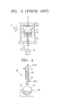
- FIG. 3 shows an apparatus applied to a conventional plasma enhanced chemical vapor deposition (PECVD) method.
- PECVD plasma enhanced chemical vapor deposition
- a reactive gas is discharged in a vacuum chamber by a direct current or high-frequency electric field applied across two electrodes.
- a substrate 31 on which carbon nanotubes are to be grown is placed on a grounded lower electrode 32, and a reactive gas is supplied between an upper electrode 34 and the lower electrode 32.
- a thermal resistive heater 33 is mounted underneath the lower electrode 32, or a filament 35 is disposed between the upper electrode 34 and the lower electrode 32, to decompose the reactive gas.
- the energy needed to decompose the reactive gas and to synthesize the carbon nantotubes is supplied from a high-frequency power source 37.
- the reactive gas CH 4 , C 2 H 2 , H 2 , etc. are used.
- the conventional CVD method is favorable for mass production and advantageously does not need an additional purification process.
- the conventional physical method it is not easy to inject and control a catalyst.
- the conventional CVD method needs a high-temperature growing process and thus increases the complexity of the process, energy consumption, and costs.
- a method for manufacturing carbon nanotubes comprising: dispersing carbon nanoparticles in a strong acid solution; and heating the strong acid solution at a predetermined temperature under reflux to form carbon nanotubes from the carbon nanoparticles.
- the carbon nanoparticles are formed by laser vaporization or arc discharging.
- the strong acid solution is one selected from the group consisting of a nitric acid solution, a sulfuric acid solution, and a phosphoric acid solution, and has a concentration of about 30%.
- the carbon nanoparticles are dispersed in a nitric acid solution in a concentration of about 1%. It is preferable that the predetermined temperature at which the strong acid solution is heated is about 110-140°C.
- the carbon nanotubes can be easily manufactured on a large scale through a reaction with a strong acid solution while being refluxed.
- FIG. 4 shows a reflux apparatus applied to a carbon nanotube manufacturing method according to an embodiment of the present invention.
- a round-bottomed flask 51 is charged with a dispersion of carbon nanoparticles in a strong acid solution 60 and heated by a heater 53.
- the pH of the strong acid solution is no more than 3.
- the strong acid solvent is vaporized, rises upward through a condenser 55, is liquefied by cooling water supplied along the inner wall of the condenser 55, and falls into the round-bottomed flask 51.
- the carbon nanoparticles in the round-bottomed flask 51 are dissociated and agglomerate together to form carbon nanotubes.
- carbon nanoparticles are used as a comprehensive meaning to include various kinds of carbon nanoparticles, for example, single-walled carbon nanoparticles and multiple-welled carbon nanoparticles (which are also called “carbon nanoonion”).
- the carbon nanoparticles are formed using the above-discribed arc discharging method or a laser heating method in an apparatus of FIG. 5.
- the strong acid solution 50 includes a nitric acid, a sulfuric acid, or a phosphoric acid in a concentration of about 30%.
- the carbon nanoparticles are dispersed to a concentration of about 1% in the strong acid solution 50.
- the strong acid breaks the bonding between carbon atoms of the carbon nanotubes.
- the strong acid solution 50 containing the carbon nanotubes is heated under reflux to a temperature of about 110-140°C for at least 5 hours, for example, in an oil bath.
- the strong acid solution 50 is repeatedly refluxed at an appropriate temperature, and the carbon nanoparticles dispersed therein are rearranged into carbon nanotubes through a chemical reaction with the strong acid solution 50.
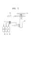
- FIG. 5 shows an apparatus applied to a carbon nanotube manufacturing method according to another embodiment of the present invention in which carbon nanotubes are formed from carbon nanoparticules by laser heating.
- the apparatus shown in FIG. 5 is constructed by incorporating an additional laser source into an apparatus for generating and growing carbon nanoparticles in a flame by flame hydrolysis deposition (FHD), so as to selectively sinter the carbon nanoparticles.
- FHD flame hydrolysis deposition
- the apparatus shown in FIG. 5 is based on the identical principles to the apparatus disclosed in Korean Laid-open Patent Publication No. 2001-51909.
- O 2 62 and H 2 64 supplied as fuels are combusted in a burner 61 to form a flame
- C 2 H 2 66 supplied as a carbon source into the burner 64 is combusted by the flame to produce carbon nanoparticles.
- a substrate 65 is disposed facing the flame from the burner 61 such that the carbon nanoparticles produced by the flame are adsorbed onto the substrate 65.
- a high-power laser source 63 which emits a laser beam to heat and sinter the carbon narnotubes produced in the flame, is disposed between the substrate 65 and the burner 64.
- the wavelength of the laser beam matches a major absorption band of the carbon nanotubes produced in the flame.
- CH 4 instead of C 2 H 2 , can be used as the carbon source.
- a CO 2 laser having a maximum power of about 2600W was used, but other laser sources can be applied.
- the temperature of the carbon nanoparticles rises to facilitate a chemical reaction and collision of the carbon nanoparticles.
- the individual carbon nanoparticles agglomerate or fuse to form a cluster of carbon nanoparticles.
- the laser heating technique can control the size of carbon nanoparticles.
- the carbon nanotubes can be produced at room temperature and atmospheric pressure, the laser heating technique is appropriate to produce carbon nanotubes on a mass scale at low costs.
- the carbon nanoparticles produced by a conventional method for example, laser vaporization or arc discharging, are used.
- the carbon nanoparticles are disposed in the strong acid solution, the carbon nanotubes having weak bonds of carbon atoms are broken and agglomerate to be grown into carbon nanotubes.
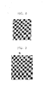
- FIG. 6 is a transmission electron microscopic (TEM) photograph of carbon nanoparticles before being applied to form carbon nanotubes
- FIG. 7 is a TEM photograph of the carbon nanotubes 70 produced from the carbon nanoparticles by the carbon nanotube manufacturing method according to an embodiment of the present invention.
- rod-like carbon nanotubes 70 which are not shown in FIG. 6, are apparent.
- carbon nanotubes can be simply formed on a large scale at low costs, through a chemical reaction between carbon nanoparticles and a strong acid solution.
- the new carbon nanotube manufacturing method is distinguished from conventional methods.
- carbon nanoparticles formed by a conventional method are dispersed in a strong acid solution and fluxed to form the carbon nanotubes.
- the overall process is simple and can be applied to mass-scale production at low costs.
Landscapes
- Chemical & Material Sciences (AREA)
- Engineering & Computer Science (AREA)
- Nanotechnology (AREA)
- Materials Engineering (AREA)
- Organic Chemistry (AREA)
- Crystallography & Structural Chemistry (AREA)
- Physics & Mathematics (AREA)
- Condensed Matter Physics & Semiconductors (AREA)
- General Physics & Mathematics (AREA)
- Inorganic Chemistry (AREA)
- Chemical Kinetics & Catalysis (AREA)
- Manufacturing & Machinery (AREA)
- Composite Materials (AREA)
- Carbon And Carbon Compounds (AREA)
Abstract
Description
Claims (6)
- A method for manufacturing carbon nanotubes, comprising:dispersing carbon nanoparticles in a strong acid solution; andheating the strong acid solution at a predetermined temperature under reflux to form carbon nanotubes from the carbon nanoparticles.
- The method according to claim 1, wherein the carbon nanoparticles are formed by laser vaporization or arc discharging.
- The method according to claim 1 or 2, wherein the strong acid solution is selected from a nitric acid solution, a sulfuric acid solution, and a phosphoric acid solution.
- The method according to any of claims 1 to 3, wherein the strong acid solution has a concentration of about 30%.
- The method according to claim 1 or 2, wherein the carbon nanoparticles are dispersed in a nitric acid solution in a concentration of about 1%.
- The method according to any of claims 1 to 5, wherein the predetermined temperature at which the strong acid solution is heated is 110-140°C.
Applications Claiming Priority (2)
| Application Number | Priority Date | Filing Date | Title |
|---|---|---|---|
| KR10-2002-0005367A KR100468845B1 (en) | 2002-01-30 | 2002-01-30 | Method of fabricating carbon nano tube |
| KR2002005367 | 2002-01-30 |
Publications (2)
| Publication Number | Publication Date |
|---|---|
| EP1340714A2 true EP1340714A2 (en) | 2003-09-03 |
| EP1340714A3 EP1340714A3 (en) | 2005-03-02 |
Family
ID=27607048
Family Applications (1)
| Application Number | Title | Priority Date | Filing Date |
|---|---|---|---|
| EP03250559A Withdrawn EP1340714A3 (en) | 2002-01-30 | 2003-01-30 | Method for manufacturing carbon nanotubes |
Country Status (4)
| Country | Link |
|---|---|
| US (1) | US7078007B2 (en) |
| EP (1) | EP1340714A3 (en) |
| JP (1) | JP2003238129A (en) |
| KR (1) | KR100468845B1 (en) |
Cited By (1)
| Publication number | Priority date | Publication date | Assignee | Title |
|---|---|---|---|---|
| US7794784B2 (en) | 2003-11-07 | 2010-09-14 | Bae Systems Plc | Forming nanostructures |
Families Citing this family (11)
| Publication number | Priority date | Publication date | Assignee | Title |
|---|---|---|---|---|
| KR20050014430A (en) * | 2003-07-31 | 2005-02-07 | 삼성에스디아이 주식회사 | A composition for forming a electron emitter of flat panel display and electron emitter prepared therefrom |
| GB2413793A (en) * | 2004-05-05 | 2005-11-09 | Ntec As | Method of producing carbon nanotubes using cooled carbon anodes |
| CA2575479C (en) * | 2005-03-25 | 2012-05-22 | Institut National De La Recherche Scientifique | Methods and apparatuses for purifying carbon filamentary structures |
| KR20060104657A (en) | 2005-03-31 | 2006-10-09 | 삼성에스디아이 주식회사 | Electron-emitting device |
| KR20060104652A (en) * | 2005-03-31 | 2006-10-09 | 삼성에스디아이 주식회사 | Electron-emitting device |
| US7790243B2 (en) * | 2006-07-19 | 2010-09-07 | The Aerospace Corporation | Method for producing large-diameter 3D carbon nano-onion structures at room temperature |
| KR101717926B1 (en) | 2015-01-20 | 2017-03-20 | 재단법인 한국탄소융합기술원 | The method for preparing catalyst for manufacturing carbon nanotube and the method using thereof for manufacturing aligned carbon nanotubes |
| US9695065B2 (en) | 2015-06-03 | 2017-07-04 | Lg Nanoh2O, Inc. | Combination of chemical additives for enhancement of water flux of a membrane |
| US9731985B2 (en) | 2015-06-03 | 2017-08-15 | Lg Nanoh2O, Inc. | Chemical additives for enhancement of water flux of a membrane |
| US9724651B2 (en) | 2015-07-14 | 2017-08-08 | Lg Nanoh2O, Inc. | Chemical additives for water flux enhancement |
| CN105151634A (en) * | 2015-09-18 | 2015-12-16 | 洛阳中岩工程材料有限公司 | Conveying drive mechanism of carton sealing and packing automatic production line |
Family Cites Families (10)
| Publication number | Priority date | Publication date | Assignee | Title |
|---|---|---|---|---|
| JP2595903B2 (en) * | 1994-07-05 | 1997-04-02 | 日本電気株式会社 | Method for purifying and opening carbon nanotubes in liquid phase and method for introducing functional groups |
| GB9418937D0 (en) * | 1994-09-20 | 1994-11-09 | Isis Innovation | Opening and filling carbon nanotubes |
| US6383559B1 (en) * | 1995-12-07 | 2002-05-07 | Fuji Photo Film Co., Ltd. | Anti-reflection film and display device having the same |
| US6210858B1 (en) * | 1997-04-04 | 2001-04-03 | Fuji Photo Film Co., Ltd. | Anti-reflection film and display device using the same |
| US6641793B2 (en) * | 1998-10-02 | 2003-11-04 | University Of Kentucky Research Foundation | Method of solubilizing single-walled carbon nanotubes in organic solutions |
| KR100364095B1 (en) * | 1999-06-15 | 2002-12-12 | 일진나노텍 주식회사 | Massive purification method of carbon nanotubes |
| CN1101335C (en) * | 1999-06-16 | 2003-02-12 | 中国科学院金属研究所 | Hydrogn arc discharging method for large scale prodn. of single wall nanometer carbon tube |
| WO2001012886A1 (en) | 1999-08-12 | 2001-02-22 | Midwest Research Institute | Single-wall carbon nanotubes |
| JP3581921B2 (en) | 1999-11-29 | 2004-10-27 | 独立行政法人産業技術総合研究所 | Method for producing inorganic coprecipitate particles |
| US6846345B1 (en) * | 2001-12-10 | 2005-01-25 | The United States Of America As Represented By The Secretary Of The Navy | Synthesis of metal nanoparticle compositions from metallic and ethynyl compounds |
-
2002
- 2002-01-30 KR KR10-2002-0005367A patent/KR100468845B1/en not_active Expired - Fee Related
-
2003
- 2003-01-30 JP JP2003021913A patent/JP2003238129A/en active Pending
- 2003-01-30 US US10/353,936 patent/US7078007B2/en not_active Expired - Fee Related
- 2003-01-30 EP EP03250559A patent/EP1340714A3/en not_active Withdrawn
Cited By (1)
| Publication number | Priority date | Publication date | Assignee | Title |
|---|---|---|---|---|
| US7794784B2 (en) | 2003-11-07 | 2010-09-14 | Bae Systems Plc | Forming nanostructures |
Also Published As
| Publication number | Publication date |
|---|---|
| US20030141179A1 (en) | 2003-07-31 |
| JP2003238129A (en) | 2003-08-27 |
| KR20030065658A (en) | 2003-08-09 |
| US7078007B2 (en) | 2006-07-18 |
| KR100468845B1 (en) | 2005-01-29 |
| EP1340714A3 (en) | 2005-03-02 |
Similar Documents
| Publication | Publication Date | Title |
|---|---|---|
| JP2737736B2 (en) | Method for producing carbon single-walled nanotube | |
| US8893645B2 (en) | Method of and apparatus for synthesizing highly oriented, aligned carbon nanotubes from an organic liquid | |
| US8741419B2 (en) | Nanocarbon material-composite substrate and manufacturing method thereof | |
| US7824649B2 (en) | Apparatus and method for synthesizing a single-wall carbon nanotube array | |
| US6827823B2 (en) | Nano-carbon and composite material or mixed material containing nano-carbon and metal fine particle and methods for producing and patterning the same | |
| US7078007B2 (en) | Method for manufacturing carbon nanotubes | |
| KR20210016610A (en) | Apparatus and method for manufacturing carbon nanotubes | |
| US20050163696A1 (en) | Synthesis of carbon nanotubes by making use of microwave plasma torch | |
| US7468097B2 (en) | Method and apparatus for hydrogen production from greenhouse gas saturated carbon nanotubes and synthesis of carbon nanostructures therefrom | |
| KR101290659B1 (en) | Preparation method of silicon oxide powder using thermal plasma, and the silicon oxide powder thereby | |
| Kim et al. | Thermal plasma synthesis of ceramic nanomaterials | |
| KR20050096624A (en) | Carbon nanotubes composition apparatus using microwave plasma torch, and method thereof | |
| WO2001008795A1 (en) | Fine particle manufacturing method using laser beam | |
| KR100646221B1 (en) | Method and apparatus for manufacturing carbon nanotubes using thermal plasma torch | |
| KR20230027747A (en) | Method for manufacturing boron nitride nanotube | |
| KR101537216B1 (en) | A making process of silicon powder Using Plasma Arc Discharge | |
| JP2005263523A (en) | Mesosized fine particles and method for producing the same | |
| WO2009040256A2 (en) | System and method for preparing single-wall carbon nanotubes | |
| JP2004526652A (en) | Method for producing shell-shaped carbon fine particles | |
| KR100450028B1 (en) | Method And Apparatus For Synthesis Of Single-walled Carbon Nanotubes Through Explosion Of Hydrocarbon Compounds | |
| KR100556644B1 (en) | Carbon nanomaterial manufacturing apparatus and method using flame | |
| KR100779082B1 (en) | Plasma enhanced chemical vapor deposition apparatus, and manufacturing method of nano-structured particles | |
| KR20030080521A (en) | Method and Apparatus for Synthesis of Single-walled Carbon Nanotubes by Using Plasma | |
| KR20080052219A (en) | Carbon nanotube manufacturing apparatus and manufacturing method | |
| Barney | Fabrication Techniques for Growing Carbon Nanotubes |
Legal Events
| Date | Code | Title | Description |
|---|---|---|---|
| PUAI | Public reference made under article 153(3) epc to a published international application that has entered the european phase |
Free format text: ORIGINAL CODE: 0009012 |
|
| AK | Designated contracting states |
Kind code of ref document: A2 Designated state(s): AT BE BG CH CY CZ DE DK EE ES FI FR GB GR HU IE IT LI LU MC NL PT SE SI SK TR |
|
| AX | Request for extension of the european patent |
Extension state: AL LT LV MK RO |
|
| PUAL | Search report despatched |
Free format text: ORIGINAL CODE: 0009013 |
|
| AK | Designated contracting states |
Kind code of ref document: A3 Designated state(s): AT BE BG CH CY CZ DE DK EE ES FI FR GB GR HU IE IT LI LU MC NL PT SE SI SK TR |
|
| AX | Request for extension of the european patent |
Extension state: AL LT LV MK RO |
|
| 17P | Request for examination filed |
Effective date: 20050420 |
|
| AKX | Designation fees paid |
Designated state(s): DE FR GB |
|
| STAA | Information on the status of an ep patent application or granted ep patent |
Free format text: STATUS: THE APPLICATION IS DEEMED TO BE WITHDRAWN |
|
| 18D | Application deemed to be withdrawn |
Effective date: 20080826 |