EP1340659A2 - Parking brake actuating mechanisms - Google Patents
Parking brake actuating mechanisms Download PDFInfo
- Publication number
- EP1340659A2 EP1340659A2 EP03001606A EP03001606A EP1340659A2 EP 1340659 A2 EP1340659 A2 EP 1340659A2 EP 03001606 A EP03001606 A EP 03001606A EP 03001606 A EP03001606 A EP 03001606A EP 1340659 A2 EP1340659 A2 EP 1340659A2
- Authority
- EP
- European Patent Office
- Prior art keywords
- lever
- cable
- nipple
- passage
- brake
- Prior art date
- Legal status (The legal status is an assumption and is not a legal conclusion. Google has not performed a legal analysis and makes no representation as to the accuracy of the status listed.)
- Granted
Links
- 230000007246 mechanism Effects 0.000 title claims abstract description 52
- 210000002445 nipple Anatomy 0.000 claims abstract description 49
- 230000015572 biosynthetic process Effects 0.000 claims abstract description 35
- 238000003780 insertion Methods 0.000 description 2
- 230000037431 insertion Effects 0.000 description 2
- 238000009434 installation Methods 0.000 description 2
- 238000007493 shaping process Methods 0.000 description 2
- 239000002184 metal Substances 0.000 description 1
- 238000000034 method Methods 0.000 description 1
Images


Classifications
-
- F—MECHANICAL ENGINEERING; LIGHTING; HEATING; WEAPONS; BLASTING
- F16—ENGINEERING ELEMENTS AND UNITS; GENERAL MEASURES FOR PRODUCING AND MAINTAINING EFFECTIVE FUNCTIONING OF MACHINES OR INSTALLATIONS; THERMAL INSULATION IN GENERAL
- F16D—COUPLINGS FOR TRANSMITTING ROTATION; CLUTCHES; BRAKES
- F16D65/00—Parts or details
- F16D65/14—Actuating mechanisms for brakes; Means for initiating operation at a predetermined position
- F16D65/16—Actuating mechanisms for brakes; Means for initiating operation at a predetermined position arranged in or on the brake
- F16D65/22—Actuating mechanisms for brakes; Means for initiating operation at a predetermined position arranged in or on the brake adapted for pressing members apart, e.g. for drum brakes
-
- B—PERFORMING OPERATIONS; TRANSPORTING
- B60—VEHICLES IN GENERAL
- B60T—VEHICLE BRAKE CONTROL SYSTEMS OR PARTS THEREOF; BRAKE CONTROL SYSTEMS OR PARTS THEREOF, IN GENERAL; ARRANGEMENT OF BRAKING ELEMENTS ON VEHICLES IN GENERAL; PORTABLE DEVICES FOR PREVENTING UNWANTED MOVEMENT OF VEHICLES; VEHICLE MODIFICATIONS TO FACILITATE COOLING OF BRAKES
- B60T1/00—Arrangements of braking elements, i.e. of those parts where braking effect occurs specially for vehicles
- B60T1/02—Arrangements of braking elements, i.e. of those parts where braking effect occurs specially for vehicles acting by retarding wheels
- B60T1/06—Arrangements of braking elements, i.e. of those parts where braking effect occurs specially for vehicles acting by retarding wheels acting otherwise than on tread, e.g. employing rim, drum, disc, or transmission or on double wheels
- B60T1/067—Arrangements of braking elements, i.e. of those parts where braking effect occurs specially for vehicles acting by retarding wheels acting otherwise than on tread, e.g. employing rim, drum, disc, or transmission or on double wheels employing drum
-
- B—PERFORMING OPERATIONS; TRANSPORTING
- B60—VEHICLES IN GENERAL
- B60T—VEHICLE BRAKE CONTROL SYSTEMS OR PARTS THEREOF; BRAKE CONTROL SYSTEMS OR PARTS THEREOF, IN GENERAL; ARRANGEMENT OF BRAKING ELEMENTS ON VEHICLES IN GENERAL; PORTABLE DEVICES FOR PREVENTING UNWANTED MOVEMENT OF VEHICLES; VEHICLE MODIFICATIONS TO FACILITATE COOLING OF BRAKES
- B60T11/00—Transmitting braking action from initiating means to ultimate brake actuator without power assistance or drive or where such assistance or drive is irrelevant
- B60T11/04—Transmitting braking action from initiating means to ultimate brake actuator without power assistance or drive or where such assistance or drive is irrelevant transmitting mechanically
- B60T11/046—Using cables
-
- F—MECHANICAL ENGINEERING; LIGHTING; HEATING; WEAPONS; BLASTING
- F16—ENGINEERING ELEMENTS AND UNITS; GENERAL MEASURES FOR PRODUCING AND MAINTAINING EFFECTIVE FUNCTIONING OF MACHINES OR INSTALLATIONS; THERMAL INSULATION IN GENERAL
- F16C—SHAFTS; FLEXIBLE SHAFTS; ELEMENTS OR CRANKSHAFT MECHANISMS; ROTARY BODIES OTHER THAN GEARING ELEMENTS; BEARINGS
- F16C1/00—Flexible shafts; Mechanical means for transmitting movement in a flexible sheathing
- F16C1/10—Means for transmitting linear movement in a flexible sheathing, e.g. "Bowden-mechanisms"
- F16C1/12—Arrangements for transmitting movement to or from the flexible member
-
- F—MECHANICAL ENGINEERING; LIGHTING; HEATING; WEAPONS; BLASTING
- F16—ENGINEERING ELEMENTS AND UNITS; GENERAL MEASURES FOR PRODUCING AND MAINTAINING EFFECTIVE FUNCTIONING OF MACHINES OR INSTALLATIONS; THERMAL INSULATION IN GENERAL
- F16C—SHAFTS; FLEXIBLE SHAFTS; ELEMENTS OR CRANKSHAFT MECHANISMS; ROTARY BODIES OTHER THAN GEARING ELEMENTS; BEARINGS
- F16C2361/00—Apparatus or articles in engineering in general
- F16C2361/45—Brakes
-
- F—MECHANICAL ENGINEERING; LIGHTING; HEATING; WEAPONS; BLASTING
- F16—ENGINEERING ELEMENTS AND UNITS; GENERAL MEASURES FOR PRODUCING AND MAINTAINING EFFECTIVE FUNCTIONING OF MACHINES OR INSTALLATIONS; THERMAL INSULATION IN GENERAL
- F16D—COUPLINGS FOR TRANSMITTING ROTATION; CLUTCHES; BRAKES
- F16D2121/00—Type of actuator operation force
- F16D2121/02—Fluid pressure
-
- F—MECHANICAL ENGINEERING; LIGHTING; HEATING; WEAPONS; BLASTING
- F16—ENGINEERING ELEMENTS AND UNITS; GENERAL MEASURES FOR PRODUCING AND MAINTAINING EFFECTIVE FUNCTIONING OF MACHINES OR INSTALLATIONS; THERMAL INSULATION IN GENERAL
- F16D—COUPLINGS FOR TRANSMITTING ROTATION; CLUTCHES; BRAKES
- F16D2121/00—Type of actuator operation force
- F16D2121/14—Mechanical
-
- F—MECHANICAL ENGINEERING; LIGHTING; HEATING; WEAPONS; BLASTING
- F16—ENGINEERING ELEMENTS AND UNITS; GENERAL MEASURES FOR PRODUCING AND MAINTAINING EFFECTIVE FUNCTIONING OF MACHINES OR INSTALLATIONS; THERMAL INSULATION IN GENERAL
- F16D—COUPLINGS FOR TRANSMITTING ROTATION; CLUTCHES; BRAKES
- F16D2125/00—Components of actuators
- F16D2125/18—Mechanical mechanisms
- F16D2125/58—Mechanical mechanisms transmitting linear movement
- F16D2125/60—Cables or chains, e.g. Bowden cables
- F16D2125/62—Fixing arrangements therefor, e.g. cable end attachments
-
- F—MECHANICAL ENGINEERING; LIGHTING; HEATING; WEAPONS; BLASTING
- F16—ENGINEERING ELEMENTS AND UNITS; GENERAL MEASURES FOR PRODUCING AND MAINTAINING EFFECTIVE FUNCTIONING OF MACHINES OR INSTALLATIONS; THERMAL INSULATION IN GENERAL
- F16D—COUPLINGS FOR TRANSMITTING ROTATION; CLUTCHES; BRAKES
- F16D2125/00—Components of actuators
- F16D2125/18—Mechanical mechanisms
- F16D2125/58—Mechanical mechanisms transmitting linear movement
- F16D2125/68—Lever-link mechanisms, e.g. toggles with change of force ratio
Definitions
- This invention relates to parking brake actuating mechanisms and particularly to such mechanisms, hereinafter being referred to as of the kind specified, comprising a first lever having a first contact zone adapted to engage a first brake shoe portion, said first lever being pivotally connected with a second lever, the second lever having a second contact zone adapted to engage a second brake shoe portion, pivoting of the first lever relative to the second lever being arranged to increase the effective length of the mechanism between the contact portions thus moving the associated brake shoe portions apart to engage the parking brake.
- a parking brake actuating mechanism of the type specified in which the first lever includes an actuating cable abutment formation against which an actuating cable nipple on a free end of the cable is drawn to move the first lever hence operating the mechanism, the first lever also being of hollow form defining a guide passage through which the free end of the cable is directed from an aperture in the backplate of the associated brake to a location adjacent to the abutment formation to enable the nipple to be engaged with the formation.
- a brake actuating mechanism hereinafter being referred to as of the kind claimed.
- a spring means is provided which tends to maintain the cable nipple in a position for engagement with the abutment formation on the first lever.
- the spring means may comprise a leaf-spring carried on the first lever which tends to maintain the cable in a portion of the first lever where is will remain engaged with the abutment formation.
- the guide passage through the hollow lever has a cross section part of which allows the passage therethrough of the cable nipple and part of which is narrow and will not allow passage of the nipple, one end of the narrow portion of the passage forming the abutment formation and the spring means tending to maintain the cable in the narrow part of the passage after the free end of the cable has emerged from the passage.
- the leaf-spring may also be shaped to tend to deflect the nipple towards the abutment formation when it emerges from the passage.
- the leaf spring is preferably shaped to limit the distance which the nipple can move away from the abutment formation. This shaping of the leaf spring also stops over insertion of the cable into the brake during installation.
- the leaf spring may be shaped to apply pressure to the nipple to retain the nipple against the abutment formation.
- the first lever is shaped to tend to hold the cable nipple in engagement with the abutment formation when the cable is pulled to operate the mechanism.
- the guide passage through the hollow lever to have a cross section part of which has a wider cross section which allows the passage therethrough of the cable nipple and part of which is narrow and will not allow passage of the nipple, one end of the narrow portion of the passage forming the abutment formation against the nipple is drawn after the free end of the cable has emerged from the passage and this end of the narrow portion of the passage being inclined to the line of action of the cable to bias the nipple and hence the associated portion of the cable into the narrow portion of the passage when the cable is pulled to operate the mechanism.
- the spring means may be used in combination with the shaping of the first lever the second to provide a particularly reliable arrangement for ensuring that the nipple remains in contact with the abutment formation. Alternatively, these features may be used separately.
- a spring guide may also be used to guide the free end of the cable from the aperture in the backplate into the hollow guide passage of the first lever.
- This spring guide may also act as a return spring for the parking brake actuating mechanism to help disengage the parking brake when the cable is released.
- a spring guide will comprise a coil spring, extending between the backplate and the first lever down the centre of which the cable is threaded.
- the second lever may also be shaped to assist in guiding the nipple into engagement with the abutment formation when the nipple emerges from the passage.
- a parking brake actuating mechanism in accordance with the invention is suitable for use in a normal drum brake or in a so-called drum-in-disc brake. Also, the mechanism may be engaged between portions of separate brake shoes or between different portions of a single curved brake shoe.
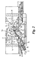
- the drum -in- disc parking brake mechanism 10 comprises a first lever 11 having a first contact zone 12 for engagement with a web 13 of an associated brake shoe 14 and a second lever 15 having a second contact surface 16 for engagement with the web 17 of a second brake shoe 18.
- the two levers 11 and 15 are pivotally interconnected at 19 so that, in conventional manner, pivoting of first lever in direction P results in an increase in the distance between the first and second contact zones 12 and 16 to force the brake shoes 14 and 18 apart causing them to engage with an associated drum (not shown).
- the brake includes return springs 20 and 21 which acts between the shoes and an adjustment device 22 enabling the drum brake to be manually adjusted.
- second lever 15 has two limbs 15a and 15b joined by a bridging piece 15c.
- first lever 11 is of hollow pressed metal form and includes a longitudinally extending passage 29 whose cross section includes a wider portion 30(see Fig 4) through which the nipple 28 can pass and a narrower portion 31 through which the nipple cannot pass.
- the inner 27 of the cable can be threaded through the wider portion 30 of passage 29.
- a leaf spring 40 is mounted on lever 11 in a notch 41 by clip portion 42 and tabs 43.
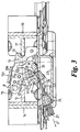
- Spring 40 includes a cam portion 44 which is contacted by the nipple 28 as the nipple emerges from the passage 29 and which tends to deflect the nipple 28 towards a fully installed position shown in Figure 3 in which a shoulder 33 of nipple 28 contacts an end 31a of the narrow portion 31 of passage 29 when the cable inner 27 is drawn in direction Z of figure 2 so that the first lever 11 is pivoted in direction P and hence the actuating mechanism is operated. End 31a of narrow passage portion31 forms the abutment formation of lever 11.
- the end of the passage 29 is shaped in regions 29a and 29b so as to tend to retain the nipple 28 in a position to engage end 31a of the narrow passage portion 31.
- the shoulder region 29a is shaped in regions 29a and 29b so as to tend to retain the nipple 28 in a position to engage end 31a of the narrow passage portion 31.
- the leaf spring 40 limits the distance which the nipple can move away from the abutment formation 31a. This is particularly useful in preventing disengagement of the cable from lever 11 prior to final adjustment of the cable on a vehicle assembly line.
- the leaf spring also limits the extent to which the cable can be inserted into the brake during installation. This prevents over insertion of the cable.
- the leaf spring 40 may additionally be arranged to apply pressure to nipple 28 when the nipple is in the fully installed position shown in Figure 3 to assist in retaining the nipple against the end portion 31a of lever 11.
Landscapes
- Engineering & Computer Science (AREA)
- Mechanical Engineering (AREA)
- General Engineering & Computer Science (AREA)
- Transportation (AREA)
- Health & Medical Sciences (AREA)
- Oral & Maxillofacial Surgery (AREA)
- Braking Arrangements (AREA)
Abstract
Description
Claims (15)
- A parking brake actuating mechanisms (10) comprising a first lever (11) having a first contact zone (12) adapted to engage a first brake shoe portion (13), said first lever being pivotally connected (19) with a second lever(15), the second lever having a second contact zone (16) adapted to engage a second brake shoe portion (17), pivoting (P) of the first lever relative to the second lever being arranged to increase the effective length of the mechanism between the contact portions thus moving the associated brake shoe portions apart to engage the parking brake, the first lever including an actuating cable abutment formation (31a) against which an actuating cable nipple (28) on a free end of a cable (27) is drawn to move the first lever (11) hence operating the mechanism, the first lever also being of hollow form defining a guide passage (29) through which the free end of the cable is directed from an aperture (24) in the backplate (23) of the associated brake to a location adjacent to the abutment formation (31 a) to enable the nipple to be engaged with the formation, the actuating mechanism being characterised in that spring means (40) is provided to tend to maintain the cable nipple (28) in position for engagement with the abutment formation (31a) on the first lever (11).
- An actuating mechanism according to claim 1 characterised in that the spring means comprises a leaf spring (41) carried on the first lever (11) which tends to maintain the cable (27) in a portion of the first lever where it will remain engaged with the abutment formation (31a).
- An actuating mechanism according to claim 2 characterised in that the leaf spring (40) is also shaped (44) to tend to deflect the nipple towards the abutment formation (31a) when it emerges from the passage (29).
- An actuating mechanism according to claim 2 or 3 characterised in that the leaf spring (40) is shaped to limit the distance which the nipple (28) can move away from the abutment formation (31a).
- An actuating mechanism according to any one of claims 2 to 4 characterised in that the leaf spring (40) is shaped to apply pressure to the nipple (28) to retain the nipple against the abutment formation (31a).
- An actuating mechanism according to any one of claims 1 to 5 characterised in that the guide passage (29) through the hollow lever (11) has a cross section part (30) of which allows the passage therethrough of the cable nipple (28) and part (31) of which is narrow and will not allow passage of the nipple (28), one end (31a) of the narrow portion (31) of the passage forming the abutment formation and the spring means (40) tending to maintain the cable (27) in the narrow part (31) of the passage (29) after the free end of the cable has emerged from the passage.
- A brake actuating mechanism according to claim 6 characterised in that the narrow portion (31) of the passage (29) is inclined (29a,29b) to the line of action of the cable (27) to bias the nipple (28) and hence the associated portion of the cable (27) into the narrow portion (31) of the passage (29) when the cable is pulled (Z) to operate the mechanism.
- A brake actuating mechanism comprising a first lever (11) having a first contact zone (12) adapted to engage a first brake shoe portion (13), said first lever being pivotally connected (19) with a second lever (15), the second lever having a second contact zone (16) adapted to engage a second brake shoe portion (17), pivoting (P) of the first lever (11) relative to the second lever (12) being arranged to increase the effective length of the mechanism between the contact portions thus moving the associated brake shoe portions apart to engage the parking brake, the first lever including an actuating cable abutment formation (31a) against which an actuating cable nipple (28) on a free end of a cable (27) is drawn to move the first lever (11) hence operating the mechanism, the first lever also being of hollow form defining a guide passage (29) through which the free end of the cable (27) is directed from an aperture in the backplate of the associated brake to a location adjacent to the abutment formation (31a) to enable the nipple (28) to be engaged with the formation, the actuating mechanism being characterised in that the first lever (11) is shaped (29a,29b) to tend to hold the cable nipple (28) in engagement with the abutment formation (31a) when the cable (27) is pulled (Z) to operate the mechanism.
- A brake actuating mechanism according to claim 8 characterised in that the guide passage (29) through the hollow lever (11) has a cross section part (30) of which has a wider cross section which allows the passage therethrough of the cable nipple (28) and part (31) of which is narrow and will not allow passage of the nipple (28), one end (31a) of the narrow portion (31) of the passage forming the abutment formation and the spring means (40) tending to maintain the cable (27) in the narrow part (31) of the passage (29) after the free end of the cable has emerged from the passage.
- A brake actuating mechanism according to any one of claims 1 to 9 characterised in that a spring guide is used to guide the free end (28) of the cable (27) from the aperture (24) in the backplate (23) into the hollow guide passage (29) of the first lever (11).
- A brake actuating mechanism according to claim 10 characterised in that the guide spring also acts as a return spring for the parking brake actuating mechanism to help disengage the parking brake when the cable (27) is released.
- A brake actuating mechanism according to claim 10 or 11 characterised in that the spring guide comprises a coil spring extending between the backplate (23) and the first lever (11) down the centre of which the cable (27) is threaded.
- A brake actuating mechanism according to any one of claims 1 to 12 characterised in that the second lever (15) is also shaped to assist in guiding the nipple (28) into engagement with the abutment formation (31a) when the nipple emerges from the passage (29).
- A brake actuating mechanism according to any one of claims 1 to 13 characterised in that the mechanism is engaged between portions (13,17) of separate brake shoes (14,18) or between different portions of a single curved brake shoe.
- A parking brake characterised by the inclusion of an actuating mechanism (10) in accordance with any one of claims 1 to 14.
Applications Claiming Priority (2)
| Application Number | Priority Date | Filing Date | Title |
|---|---|---|---|
| GB0203894 | 2002-02-19 | ||
| GBGB0203894.1A GB0203894D0 (en) | 2002-02-19 | 2002-02-19 | Parking brake actuating mechanisms |
Publications (3)
| Publication Number | Publication Date |
|---|---|
| EP1340659A2 true EP1340659A2 (en) | 2003-09-03 |
| EP1340659A3 EP1340659A3 (en) | 2004-01-14 |
| EP1340659B1 EP1340659B1 (en) | 2012-09-05 |
Family
ID=9931361
Family Applications (1)
| Application Number | Title | Priority Date | Filing Date |
|---|---|---|---|
| EP03001606A Expired - Lifetime EP1340659B1 (en) | 2002-02-19 | 2003-01-24 | Parking brake actuating mechanisms |
Country Status (2)
| Country | Link |
|---|---|
| EP (1) | EP1340659B1 (en) |
| GB (2) | GB0203894D0 (en) |
Cited By (2)
| Publication number | Priority date | Publication date | Assignee | Title |
|---|---|---|---|---|
| CN111936760A (en) * | 2018-03-30 | 2020-11-13 | 日信工业株式会社 | Electric parking brake device |
| CN112901676A (en) * | 2021-01-26 | 2021-06-04 | 浙江亚太机电股份有限公司 | Drum brake stay wire installation guiding mechanism |
Family Cites Families (7)
| Publication number | Priority date | Publication date | Assignee | Title |
|---|---|---|---|---|
| WO1991015685A1 (en) * | 1990-03-31 | 1991-10-17 | Alfred Teves Gmbh | Brake cable fixing for a parking brake, especially for a duo-servo chamber hand-brake |
| DE19604403A1 (en) * | 1996-02-07 | 1997-08-14 | Teves Gmbh Alfred | Expansion lock for a duo servo pot handbrake |
| JP2000108856A (en) * | 1998-10-05 | 2000-04-18 | Hosei Brake Ind Ltd | Right angle cable parking brake |
| GB9922003D0 (en) * | 1999-09-18 | 1999-11-17 | Automotive Prod Italia | Parking brake actuating mechanism |
| JP4397080B2 (en) * | 1999-11-02 | 2010-01-13 | 日清紡ホールディングス株式会社 | Operation cable connection device |
| JP4794723B2 (en) * | 2000-07-17 | 2011-10-19 | 日清紡ホールディングス株式会社 | Brake cable connection device |
| JP2002364688A (en) * | 2001-06-08 | 2002-12-18 | Nisshinbo Ind Inc | Brake cable connection device |
-
2002
- 2002-02-19 GB GBGB0203894.1A patent/GB0203894D0/en not_active Ceased
-
2003
- 2003-01-23 GB GB0301516A patent/GB2386654B/en not_active Expired - Fee Related
- 2003-01-24 EP EP03001606A patent/EP1340659B1/en not_active Expired - Lifetime
Cited By (4)
| Publication number | Priority date | Publication date | Assignee | Title |
|---|---|---|---|---|
| CN111936760A (en) * | 2018-03-30 | 2020-11-13 | 日信工业株式会社 | Electric parking brake device |
| CN111936760B (en) * | 2018-03-30 | 2022-04-19 | 日立安斯泰莫株式会社 | Electric parking brake device |
| US11400908B2 (en) | 2018-03-30 | 2022-08-02 | Hitachi Astemo, Ltd. | Electric parking brake device |
| CN112901676A (en) * | 2021-01-26 | 2021-06-04 | 浙江亚太机电股份有限公司 | Drum brake stay wire installation guiding mechanism |
Also Published As
| Publication number | Publication date |
|---|---|
| EP1340659B1 (en) | 2012-09-05 |
| GB0203894D0 (en) | 2002-04-03 |
| GB2386654A (en) | 2003-09-24 |
| EP1340659A3 (en) | 2004-01-14 |
| GB2386654B (en) | 2005-08-17 |
| GB0301516D0 (en) | 2003-02-19 |
Similar Documents
| Publication | Publication Date | Title |
|---|---|---|
| US5950496A (en) | Parking brake for motor vehicles trailers or the like | |
| US5311793A (en) | Brake cable fixing device for a parking brake, in particular for a duo-servo hat-section-type parking brake | |
| US4955458A (en) | Blind assembly of parking brake cable to parking brake lever | |
| US6651782B2 (en) | Brake cable connecting apparatus for drum brake | |
| US7654372B2 (en) | Shoe-hold apparatus for drum brake device | |
| US3661233A (en) | Internal shoe drum brakes | |
| US6802397B1 (en) | Automatic cable latching device for drum brake levers | |
| US5377789A (en) | Snap-in park brake cable | |
| US20060144658A1 (en) | Parking brake of a drum brake | |
| EP1265001A2 (en) | Brake cable connecting apparatus for a drum brake device | |
| EP1340659B1 (en) | Parking brake actuating mechanisms | |
| EP1131569B1 (en) | Parking brake actuating mechanism | |
| US4886134A (en) | Blind cable assembly | |
| EP1174627B9 (en) | Brake cable connecting apparatus for drum brake | |
| JPH06156251A (en) | Adjusting device for brake | |
| US5419216A (en) | Self-adjusting actuation mechanism | |
| EP1234995B1 (en) | Apparatus for connecting a brake cable to the actuating lever of a drum brake | |
| JPH0461975B2 (en) | ||
| US4974708A (en) | Drum brake with postponed fitting of the mechanical control cable | |
| JP4549852B2 (en) | Cable-driven drum brake | |
| US20060075844A1 (en) | Brake cable connecting apparatus for a drum brake device | |
| CN101460759A (en) | Drum brakes | |
| EP0147060B1 (en) | Internal shoe drum brake | |
| EP1561047B1 (en) | Parking brake assemblies with automatic cable latching | |
| JP2005113996A (en) | Drum brake device |
Legal Events
| Date | Code | Title | Description |
|---|---|---|---|
| PUAI | Public reference made under article 153(3) epc to a published international application that has entered the european phase |
Free format text: ORIGINAL CODE: 0009012 |
|
| AK | Designated contracting states |
Kind code of ref document: A2 Designated state(s): AT BE BG CH CY CZ DE DK EE ES FI FR GB GR HU IE IT LI LU MC NL PT SE SI SK TR |
|
| AX | Request for extension of the european patent |
Extension state: AL LT LV MK RO |
|
| PUAL | Search report despatched |
Free format text: ORIGINAL CODE: 0009013 |
|
| AK | Designated contracting states |
Kind code of ref document: A3 Designated state(s): AT BE BG CH CY CZ DE DK EE ES FI FR GB GR HU IE IT LI LU MC NL PT SE SI SK TR |
|
| AX | Request for extension of the european patent |
Extension state: AL LT LV MK RO |
|
| RIC1 | Information provided on ipc code assigned before grant |
Ipc: 7F 16D 65/22 B Ipc: 7F 16D 51/22 B Ipc: 7B 60T 1/06 A |
|
| 17P | Request for examination filed |
Effective date: 20040708 |
|
| AKX | Designation fees paid |
Designated state(s): DE FR GB IT |
|
| 17Q | First examination report despatched |
Effective date: 20070524 |
|
| GRAP | Despatch of communication of intention to grant a patent |
Free format text: ORIGINAL CODE: EPIDOSNIGR1 |
|
| GRAS | Grant fee paid |
Free format text: ORIGINAL CODE: EPIDOSNIGR3 |
|
| GRAA | (expected) grant |
Free format text: ORIGINAL CODE: 0009210 |
|
| AK | Designated contracting states |
Kind code of ref document: B1 Designated state(s): DE FR GB IT |
|
| REG | Reference to a national code |
Ref country code: GB Ref legal event code: FG4D |
|
| REG | Reference to a national code |
Ref country code: DE Ref legal event code: R096 Ref document number: 60341996 Country of ref document: DE Effective date: 20121031 |
|
| PLBE | No opposition filed within time limit |
Free format text: ORIGINAL CODE: 0009261 |
|
| STAA | Information on the status of an ep patent application or granted ep patent |
Free format text: STATUS: NO OPPOSITION FILED WITHIN TIME LIMIT |
|
| 26N | No opposition filed |
Effective date: 20130606 |
|
| REG | Reference to a national code |
Ref country code: DE Ref legal event code: R097 Ref document number: 60341996 Country of ref document: DE Effective date: 20130606 |
|
| REG | Reference to a national code |
Ref country code: DE Ref legal event code: R081 Ref document number: 60341996 Country of ref document: DE Owner name: CONTINENTAL TEVES AG & CO. OHG, DE Free format text: FORMER OWNER: AUTOMOTIVE PRODUCTS (ITALIA) S.P.A., CAIRO MONTENOTTE, IT Effective date: 20120905 Ref country code: DE Ref legal event code: R081 Ref document number: 60341996 Country of ref document: DE Owner name: CONTINENTAL TEVES AG & CO. OHG, DE Free format text: FORMER OWNER: AUTOMOTIVE PRODUCTS (ITALIA) S.P.A., CAIRO MONTENOTTE, IT Effective date: 20140206 Ref country code: DE Ref legal event code: R081 Ref document number: 60341996 Country of ref document: DE Owner name: CONTINENTAL TEVES AG & CO. OHG, DE Free format text: FORMER OWNER: AUTOMOTIVE PRODUCTS (ITALIA) S.P.A., CAIRO MONTENOTTE, SAVONA, IT Effective date: 20140206 Ref country code: DE Ref legal event code: R081 Ref document number: 60341996 Country of ref document: DE Owner name: CONTINENTAL TEVES AG & CO. OHG, DE Free format text: FORMER OWNER: AUTOMOTIVE PRODUCTS (ITALIA) S.P.A., CAIRO MONTENOTTE, SAVONA, IT Effective date: 20120905 |
|
| REG | Reference to a national code |
Ref country code: FR Ref legal event code: PLFP Year of fee payment: 14 |
|
| REG | Reference to a national code |
Ref country code: FR Ref legal event code: PLFP Year of fee payment: 15 |
|
| PGFP | Annual fee paid to national office [announced via postgrant information from national office to epo] |
Ref country code: FR Payment date: 20170120 Year of fee payment: 15 |
|
| PGFP | Annual fee paid to national office [announced via postgrant information from national office to epo] |
Ref country code: GB Payment date: 20170119 Year of fee payment: 15 |
|
| GBPC | Gb: european patent ceased through non-payment of renewal fee |
Effective date: 20180124 |
|
| PG25 | Lapsed in a contracting state [announced via postgrant information from national office to epo] |
Ref country code: FR Free format text: LAPSE BECAUSE OF NON-PAYMENT OF DUE FEES Effective date: 20180131 |
|
| REG | Reference to a national code |
Ref country code: FR Ref legal event code: ST Effective date: 20180928 |
|
| PG25 | Lapsed in a contracting state [announced via postgrant information from national office to epo] |
Ref country code: GB Free format text: LAPSE BECAUSE OF NON-PAYMENT OF DUE FEES Effective date: 20180124 |
|
| PGFP | Annual fee paid to national office [announced via postgrant information from national office to epo] |
Ref country code: IT Payment date: 20190124 Year of fee payment: 17 Ref country code: DE Payment date: 20190131 Year of fee payment: 17 |
|
| REG | Reference to a national code |
Ref country code: DE Ref legal event code: R119 Ref document number: 60341996 Country of ref document: DE |
|
| PG25 | Lapsed in a contracting state [announced via postgrant information from national office to epo] |
Ref country code: DE Free format text: LAPSE BECAUSE OF NON-PAYMENT OF DUE FEES Effective date: 20200801 |
|
| PG25 | Lapsed in a contracting state [announced via postgrant information from national office to epo] |
Ref country code: IT Free format text: LAPSE BECAUSE OF NON-PAYMENT OF DUE FEES Effective date: 20200124 |