EP1340658A1 - Wheel clamp - Google Patents
Wheel clamp Download PDFInfo
- Publication number
- EP1340658A1 EP1340658A1 EP03251229A EP03251229A EP1340658A1 EP 1340658 A1 EP1340658 A1 EP 1340658A1 EP 03251229 A EP03251229 A EP 03251229A EP 03251229 A EP03251229 A EP 03251229A EP 1340658 A1 EP1340658 A1 EP 1340658A1
- Authority
- EP
- European Patent Office
- Prior art keywords
- arms
- wheel
- clamp
- clamp body
- arm
- Prior art date
- Legal status (The legal status is an assumption and is not a legal conclusion. Google has not performed a legal analysis and makes no representation as to the accuracy of the status listed.)
- Granted
Links
- 238000000926 separation method Methods 0.000 description 7
- 235000014036 Castanea Nutrition 0.000 description 1
- 241001070941 Castanea Species 0.000 description 1
- 230000000712 assembly Effects 0.000 description 1
- 238000000429 assembly Methods 0.000 description 1
- 238000005553 drilling Methods 0.000 description 1
- 238000004519 manufacturing process Methods 0.000 description 1
- 230000000717 retained effect Effects 0.000 description 1
- 238000005096 rolling process Methods 0.000 description 1
- 238000005728 strengthening Methods 0.000 description 1
Images

Classifications
-
- B—PERFORMING OPERATIONS; TRANSPORTING
- B60—VEHICLES IN GENERAL
- B60R—VEHICLES, VEHICLE FITTINGS, OR VEHICLE PARTS, NOT OTHERWISE PROVIDED FOR
- B60R25/00—Fittings or systems for preventing or indicating unauthorised use or theft of vehicles
- B60R25/01—Fittings or systems for preventing or indicating unauthorised use or theft of vehicles operating on vehicle systems or fittings, e.g. on doors, seats or windscreens
- B60R25/09—Fittings or systems for preventing or indicating unauthorised use or theft of vehicles operating on vehicle systems or fittings, e.g. on doors, seats or windscreens by restraining wheel rotation, e.g. wheel clamps
- B60R25/093—Fittings or systems for preventing or indicating unauthorised use or theft of vehicles operating on vehicle systems or fittings, e.g. on doors, seats or windscreens by restraining wheel rotation, e.g. wheel clamps comprising ground-engaging means
Definitions
- This invention relates to a wheel clamp, specifically a clamp which can be used to embrace part of a wheel (typically a vehicle road wheel), and impede the rotation of that wheel.
- a wheel typically a vehicle road wheel
- Wheel clamps are in widespread use by local authorities, for example. They are used to prevent the unauthorised movement of vehicles. For example, the vehicle may be illegally parked and the owner may be required to pay a fine before the clamp is removed.
- a vehicle owner may use a wheel clamp to reduce the likelihood of the vehicle being stolen if it is in an insecure location accessible to potential thieves.
- top arm substantially vertical and projects upwardly from the clamp body in use
- bottom arm the other two arms project from opposed sides of the clamp body and lie at an angle below the horizontal
- the top and bottom arms each include a radial portion and an axial portion ("radial” and “axial” being considered relative to the axis of rotation of the wheel), the axial portions engaging the tread of the tyre when in use.
- At least one (and often all) of the arms is of U-shape, and so has a "return radial" portion which can pass around the rear of the wheel and prevent the removal of the clamp in an axial direction.
- At least one of the arms is removable from the clamp body to permit the bottom arms and remainder of the wheel clamp to be fitted to a vehicle wheel. When so fitted the removable arm is replaced and locked to the clamp body.
- the arms can therefore all be secured against respective parts of the wheel, and are intended to prevent the unauthorised removal of the clamp without the top arm being unlocked.
- At least one of the bottom arms will include an extension piece which projects a significant distance beyond the periphery of the wheel, the extension piece being adapted to engage the ground and/or a part of the vehicle if the wheel is rotated with the clamp in place.
- wheel clamp sold by the company Milenco Ltd., of 13 Aston Drive, Bradwell Abbey, Milton Keynes, MK13 9HA, UK, is of fixed size, i.e. it is adapted to be fitted to a wheel having a particular diameter and width.
- This design is suitable if the vehicle for which the clamp will be used is known in advance, such as a sales outlet where a number of vehicles (e.g. caravans) having similar-sized wheels may be stored in the open.
- the vehicle is not known in advance, such as is usually the case for local authorities intending to prevent the movement of illegally parked vehicles.
- all of the arms include a return radial portion, and the bottom arms are permanently secured to the body of the clamp.
- the wheel clamp it is therefore necessary either to lift the wheel (and therefore the vehicle) so that the bottom arms can be passed thereunder, or to roll the vehicle so that its wheel passes over one of the bottom arms to lie between the bottom arms.
- This wheel clamp is therefore designed to prevent the theft of vehicles such as caravans or cars which might be accessible to thieves, but which can be moved as necessary to position the wheel clamp upon the wheel; the wheel clamp is not suitable for use by local authories or the like seeking to prevent the movement of illegally parked vehicles.
- the top arm When the bottom arms are in place adjacent the wheel, the top arm is placed over the wheel and inserted into the body of the clamp, where it can be locked in place.
- the top arm slides in a channel of the clamp body, and so its orientation relative to the body is fixed. Also, the orientation of the bottom arms is fixed by their securement to the body, and so the relative angles between all of the arms are fixed.
- This wheel clamp can therefore maintain the arms at a relative angle of substantially 120°, which is the desired angle for a clamp having three arms.
- the Milenco design is not suitable for applications in which the wheel clamp may be fitted to a range of different wheel sizes, and for such applications the clamp must be adjustable. Specifically, it is necessary that the length of the arms (i.e. the radial dimension) is adjustable to accomodate different wheel diameters, and that the axial dimension of the arm or arms having a return radial portion can be varied to suit different width wheels.
- an adjustable wheel clamp is sold under the trade name "The New Defender” by SAS Security Products Ltd, of Chestnut House, Chesney Hill, Wick, Near Bristol, BS30 5NE, UK.
- the top arm has a number of positions in which it can be locked to the clamp body, and each of the bottom arms is adjustable in length.
- the adjustment is made possible by the radial portion of the bottom arms being formed as a bar and sleeve assembly, the bar being slidable within the sleeve, and securable thereto at a number of predetermined positions.
- the securement of the bar to the sleeve at one of the predetermined positions determines the length of the radial portion of each of the bottom arms, and therefore the diameter of the wheel for which the clamp is suitable.
- each of the arms includes a return radial portion. Because of this, it is necessary that the axial portion of each arm be adjustable in length, to accommodate wheels of different width. This adjustment is made possible by the axial portion of each arm being formed as a bar and sleeve assembly, the bar being slidable within the sleeve, and securable thereto at a number of predetermined positions. The securement of the bar to the sleeve at one of the predetermined positions determines the length of the axial portion of the arm, and therefore the width of the wheel for which the clamp is suitable.
- the means securing the respective bar and sleeve assemblies in their chosen positions is inaccessible when the wheel clamp is in use, to prevent the unauthorised disassembly of the wheel clamp.
- this flexibility is a positive disadvantage in that it permits the wheel clamp to be overcome either by applying sufficient force to separate the arms from the wheel, or more simply by deflating the tyre of the wheel so as to reduce its rolling radius, and allow the removal of the clamp from the wheel.
- a wheel clamp having three arms, each of the arms including a radial part and an axial part, and at least one of the arms including a return radial part, two of the arms being mounted upon a clamp body and having an adjustable radial portion, the other of the arms being lockable to the clamp body in a number of predetermined positions, characterised by means to maintain the relative angular orientation of said two of the arms.
- said other of the arms is slidably mounted to the clamp body.
- the slidable mounting is by way of a channel section carried by the clamp body.
- a lock member is mounted adjacent to the channel member for locking of the arm thereto.
- said two of the arms are maintained at an angle of substantially 120° relative to one another, and relative to said other of the arms. It will be understood that it is not necessary to maintain the arms at precisely 120° to one another (or at another angle if another angle should be chosen), and that some small angular flexibility is likely in practice due to manufacturing tolerances. However, small angular movements will not increase the separation between the axial portions significantly, and so the benefit of the present invention will be maintained.
- the means to maintain the relative angular orientation of said two of the arms are wall members which are engageable with the respective arms substantially to prevent pivoting of the arms relative to the clamp body.
- the wall members are not permanently engageable with the arms, i.e. the clamp can have a non-operational condition in which the arms can pivot relative to the clamp body, (so as to facilitate the mounting of the arms upon a stationary wheel, for example).
- the wall member(s) are carried by the other of the arms.
- the wall members can be brought into a position in which they can engage said two of the arms, and so prevent substantial movement thereof, when the other arm is brought into position, and the clamp is placed in its operational condition.
- the clamp can subsequently be locked or otherwise secured in its operational condition.
- the clamp body carries two of the arms, and those arms are preferably pivotable relative to the clamp body when the clamp is not in its operational condition.
- the clamp body also preferably includes the lock housing by way of which the other arm may be secured to the clamp body.
- the other of the arms carries the wall members.
- the wall members can comprise an edge of a cover plate carried by the other of the arms.
- the cover plate (in conjunction with the clamp body) is adapted to obscure a significant part of the wheel. This reduces the likelihood that the wheel can be accessed when the clamp is locked thereto, which access might be used in an attempt to deflate or remove the wheel from from the vehicle, as might allow the vehicle subsequently to be moved.
- all of the arms have a return radial part. In some less desirable embodiments, however, only one of the arms (typically the other of the arms) has a return radial part.
- the adjustability of the radial portion of said two of the arms is provided by a number of spaced holes in the radial portion of each arm, and securement means to fix the arm to the clamp body by way a chosen one of the spaced holes.
- the securement means must be obscured from view, or at least be substantially inaccessible, when the clamp is fitted to a wheel, to prevent unauthorised disassembly of the clamp.
- the adjustability of the other of the arms is provided by the arm being securable to the clamp body in a number of spaced positions.
- the cover plate can be secured to the other of the arms in a number of spaced positions.
- the number and spacing of the spaced positions in which the cover plate can be mounted to the arm desirably matches the number and spacing of the spaced positions in which the arm can be locked to the clamp body. This ensures that when the arm is locked to the clamp body the cover plate can assume the same position relative to the clamp body, and so in particular the wall members will be in the same position relative to the arms.
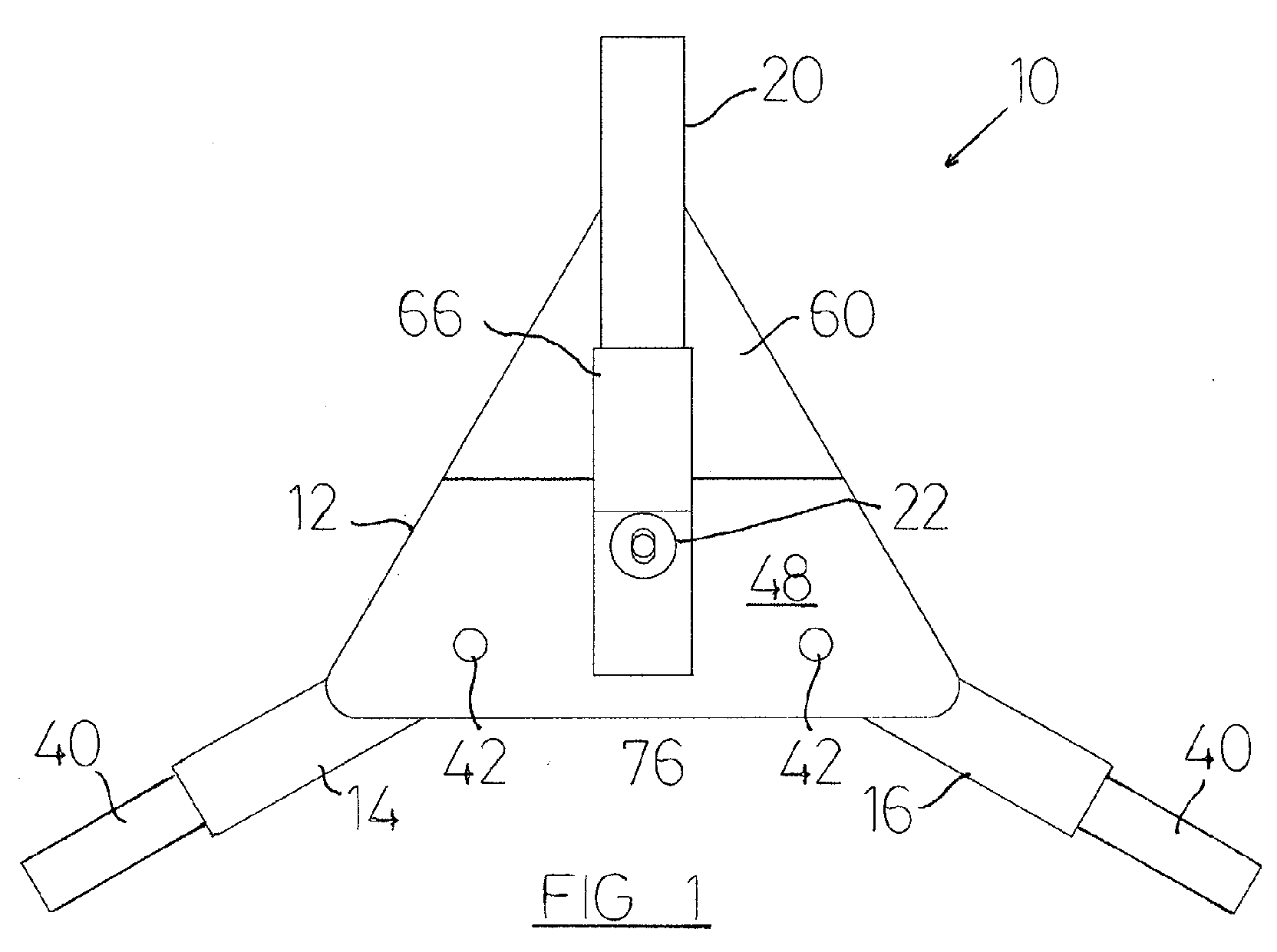
- the wheel clamp 10 comprises a clamp body 12 to which two (bottom) arms 14, 16 are attached. Another (top) arm 20 is securable to the clamp body by way of a lock (not shown) located in lock housing 22.
- the arms 14, 16 each have a radial portion 24, an axial portion 26 and a return radial portion 30.
- the top arm includes a radial portion 32, an axial portion 34 and a return radial portion 36. It will be understood that in use the radial portions 24, 32 will lie against the outside of the wheel, the axial portions 26, 34 will lie against the periphery of the wheel (and specifically against the tread of the tyre of the wheel), and the return radial portions 30, 36 will overlie respective parts of the inside of the wheel (and specifically will overlie respective parts of the inside surface of the tyre).
- Each of the bottom arms 14, 16 carry a respective extension piece 40, which projects from the axial portion of the respective arm.
- the extension piece is designed to engage a part of the bodywork of the vehicle in the event that the wheel is rotated with the wheel clamp in place.
- the bottom arms 14,16 are mounted to the clamp body 12 by way of respective pivot pegs 42 (see also Figs. 11 and 12).
- Each pivot peg 42 comprises a boss 44 and a shaft 46, the shaft 46 occupying a hole in the plate 48 which forms a part of the clamp body 12.
- the shaft 46 has a counter-bore 50 formed therein, which counter-bore is threaded.
- the radial portion 24 of each arm 14, 16 has a number of spaced holes 52 formed therein, which holes are sized to be a sliding fit over the shaft 46 of the pivot peg 42.
- the length of the shaft 46 which projects from the plate 48 is slightly greater than the thickness of the radial portion 24 of the arm 14, 16, so that when a bolt is located within the threaded counter-bore 50 it can secure the arm 14, 16 to the clamp body 12 but allow relative pivoting thereof.
- the ability of the arms 14, 16 to pivot relative to the clamp body is very desirable in practice, particularly for embodiments in which the bottom arms 14,16 have respective return radial portions.
- the top arm 20 is removed, and the bottom arms 14,16 must be fitted to the wheel with the return radial portions passing behind the wheel. This is most easily achieved if the arms 14, 16 are pivoted until they are substantially aligned (to maximise the separation of their respective axial portions), and moved alongside the bottom of the wheel, with the clamp body 12 close to the ground.
- the clamp body 12 can be lifted, whereupon the axial portions 26 of the arms 14, 16 will engage the tread of the tyre and the arms 14, 16 will move out of alignment.
- the top arm 20 is secured to a cover plate 60 (see also Figs. 5 and 6) by way of screws or bolts passing through the holes 62 in the cover plate 60 and into two of the series of spaced threaded mounting holes 64 (Fig.8) in the radial portion 32 of the arm 20.
- the cover plate 60 carries a channel section 66 through which the radial portion 32 passes, and which channel section obscures the screws or bolts and so reduces the likelihood that these can be removed by drilling or the like.
- the top arm 20 and cover plate 60 have been moved (together) to lie adjacent the clamp body 12.
- the top edge 70 (Fig. 11) of the clamp body 12 lies against (or at least very close to) the step 72 (Fig.6) in the cover plate 60.
- the channel section 66 which is carried by the cover plate 12 lies close to a similar channel section 76 (see also Figs. 10 and 11) of the clamp body 12.
- the radial portion 32 of the top arm 20 passes into the channel section 76, and the row of lock apertures 80 (Fig.8) pass beneath the lock housing 22.
- a conventional lock (not shown) can be located within the lock housing 22 and carry a movable projection which, when the lock is activated, can locate within a chosen one of the lock apertures 80, preventing separation of the top arm 20 (and hence also the cover plate 60) from the clamp body 12.
- the bottom edge of the cover plate 60 is not flat, but includes two wall members 82, 84.
- the angle ⁇ between these wall members is in this embodiment 120° (in other embodiments the angle ⁇ may be other than 120°, but it is preferred that the angle ⁇ is equal to or at least very close to 120°, for the reasons explained above.
- the wall members 82, 84 lie adjacent the radial portions 24 of the respective arm members 16, 14.
- the clamp member is drawn to show a relatively large gap between the wall members 82, 84 and the respective arm 14, 16 for reasons of clarity, but in practice that gap would be very small, or the respective parts would be touching.
- pivoting of the arm 14 either clockwise or anti-clockwise from the position shown will result in the arm engaging a part of the wall member 84, so that the pivoting of the arm members is limited and the arms 14, 16 are always retained at a relative angle of very close to the angle ⁇ .
- top arm 20 and its sliding relationship with the channel section 76 (and also the relationship of the top edge 70 of the clamp body 12 with the step 72) maintain the angular relationship between the clamp body 12 and the top arm 20, so that the angular relationship between all of the arms 14, 16, 20 can be maintained.
- the cover plate 60 also carries a strengthening plate 86, which serves to reduce or eliminate the possibility of the cover plate 60 being bent or deformed by a person intent on disabling the fitted clamp.
- the spacing s between adjacent mounting holes 64 matches the spacing s between adjacent lock apertures 80. This is necessary so that in the operative condition of the clamp the respective channel sections 66 and 76, can lie as close to each other as desired, and that the distance between the top edge 70 of the clamp body 12 and the step 72 can remain consistent, for any adjustment position of the top arm 20.
- Fig.8 It will be understood from Fig.8 that six adjustment positions are available for the bolts or screws securing the top arm 20 to the cover plate 60. This gives six possible effective lengths for the radial portion of the top arm 20.
- the spacing s in this embodiment is 20 mm, and this sets the separation between adjacent adjustment positions. The spacing s could be smaller or larger as desired, but 20 mm is believed to be an appropriate separation between adjacent adjustment positions. Also, in other embodiments more or fewer than six adjustment positions may be provided, as desired or required.
- the axial portion 26, 34 of each arm is made up of two parts, the first part comprising an angled continuation of the radial portion, the second part comprising one side of an "L-shaped" arm piece 90 (Figs. 16 and 17).
- the provision of two parts for the axial portion allows adjustment of the axial portion, specifically an adjustment of the dimension W shown in Fig.4, comprising the separation between the radial portion 24 of an arm 14, 16 and the return radial portion 30 of that arm. It will be understood that adjustment of the dimension W allows the clamp to fit wheels of differing widths.
- each L-piece includes two apertures 92.
- the remainder of the axial portion 26, 34 of the arms includes a row of seven threaded apertures 96 (the apertures in the remainder of the axial portion 26 of the arms 14, 16 are blind). Screws or bolts can be passed through the apertures 92 and into the apertures 96 to secure the L-piece to the remainder of the arm.
- the distance d can be the same as the spacing s if desired, so that adjustment in the radial and axial portions can take place in similar increments, but this need not be so.
Landscapes
- Engineering & Computer Science (AREA)
- Mechanical Engineering (AREA)
- Clamps And Clips (AREA)
- Body Structure For Vehicles (AREA)
- Vehicle Body Suspensions (AREA)
- Pressure Welding/Diffusion-Bonding (AREA)
Abstract
Description
- This invention relates to a wheel clamp, specifically a clamp which can be used to embrace part of a wheel (typically a vehicle road wheel), and impede the rotation of that wheel.
- Wheel clamps are in widespread use by local authorities, for example. They are used to prevent the unauthorised movement of vehicles. For example, the vehicle may be illegally parked and the owner may be required to pay a fine before the clamp is removed.
- Alternatively, a vehicle owner may use a wheel clamp to reduce the likelihood of the vehicle being stolen if it is in an insecure location accessible to potential thieves.
- Many different designs of wheel clamp are known, but most incorporate three arms which can lie against respective parts of the wheel. Typically, one of the arms is substantially vertical and projects upwardly from the clamp body in use, and is referred to herein as the "top arm"; the other two arms project from opposed sides of the clamp body and lie at an angle below the horizontal, and are referred to herein as the "bottom arms". The top and bottom arms each include a radial portion and an axial portion ("radial" and "axial" being considered relative to the axis of rotation of the wheel), the axial portions engaging the tread of the tyre when in use. At least one (and often all) of the arms is of U-shape, and so has a "return radial" portion which can pass around the rear of the wheel and prevent the removal of the clamp in an axial direction.
- At least one of the arms, usually the top arm, is removable from the clamp body to permit the bottom arms and remainder of the wheel clamp to be fitted to a vehicle wheel. When so fitted the removable arm is replaced and locked to the clamp body. The arms can therefore all be secured against respective parts of the wheel, and are intended to prevent the unauthorised removal of the clamp without the top arm being unlocked.
- It is understood that the arm portions of the prior art devices, and also of the present invention, need not be precisely radial and axial respectively, though this is generally preferred.
- Typically, at least one of the bottom arms will include an extension piece which projects a significant distance beyond the periphery of the wheel, the extension piece being adapted to engage the ground and/or a part of the vehicle if the wheel is rotated with the clamp in place.
- One known design of wheel clamp, sold by the company Milenco Ltd., of 13 Aston Drive, Bradwell Abbey, Milton Keynes, MK13 9HA, UK, is of fixed size, i.e. it is adapted to be fitted to a wheel having a particular diameter and width. This design is suitable if the vehicle for which the clamp will be used is known in advance, such as a sales outlet where a number of vehicles (e.g. caravans) having similar-sized wheels may be stored in the open. However, it is not suitable if the vehicle is not known in advance, such as is usually the case for local authorities intending to prevent the movement of illegally parked vehicles.
- In the Milenco design, all of the arms include a return radial portion, and the bottom arms are permanently secured to the body of the clamp. To fit the wheel clamp it is therefore necessary either to lift the wheel (and therefore the vehicle) so that the bottom arms can be passed thereunder, or to roll the vehicle so that its wheel passes over one of the bottom arms to lie between the bottom arms. This wheel clamp is therefore designed to prevent the theft of vehicles such as caravans or cars which might be accessible to thieves, but which can be moved as necessary to position the wheel clamp upon the wheel; the wheel clamp is not suitable for use by local authories or the like seeking to prevent the movement of illegally parked vehicles.
- When the bottom arms are in place adjacent the wheel, the top arm is placed over the wheel and inserted into the body of the clamp, where it can be locked in place. The top arm slides in a channel of the clamp body, and so its orientation relative to the body is fixed. Also, the orientation of the bottom arms is fixed by their securement to the body, and so the relative angles between all of the arms are fixed. This wheel clamp can therefore maintain the arms at a relative angle of substantially 120°, which is the desired angle for a clamp having three arms.
- By spacing the arms 120° apart, the spacing between the radial portions of the arms is equalised and minimised, and the likelihood of the vehicle wheel being removed from the clamp without the top arm being unlocked is reduced or eliminated.
- The Milenco design is not suitable for applications in which the wheel clamp may be fitted to a range of different wheel sizes, and for such applications the clamp must be adjustable. Specifically, it is necessary that the length of the arms (i.e. the radial dimension) is adjustable to accomodate different wheel diameters, and that the axial dimension of the arm or arms having a return radial portion can be varied to suit different width wheels.
- An adjustable wheel clamp is sold under the trade name "The New Defender" by SAS Security Products Ltd, of Chestnut House, Chesney Hill, Wick, Near Bristol, BS30 5NE, UK. In this design, the top arm has a number of positions in which it can be locked to the clamp body, and each of the bottom arms is adjustable in length. The adjustment is made possible by the radial portion of the bottom arms being formed as a bar and sleeve assembly, the bar being slidable within the sleeve, and securable thereto at a number of predetermined positions. The securement of the bar to the sleeve at one of the predetermined positions determines the length of the radial portion of each of the bottom arms, and therefore the diameter of the wheel for which the clamp is suitable.
- In this design also, each of the arms includes a return radial portion. Because of this, it is necessary that the axial portion of each arm be adjustable in length, to accommodate wheels of different width. This adjustment is made possible by the axial portion of each arm being formed as a bar and sleeve assembly, the bar being slidable within the sleeve, and securable thereto at a number of predetermined positions. The securement of the bar to the sleeve at one of the predetermined positions determines the length of the axial portion of the arm, and therefore the width of the wheel for which the clamp is suitable.
- It is arranged that the means securing the respective bar and sleeve assemblies in their chosen positions is inaccessible when the wheel clamp is in use, to prevent the unauthorised disassembly of the wheel clamp.
- It is a particular disadvantage of the SAS design of wheel clamp that the angular relationship between the arms is not fixed. Thus, whilst the orientation of the top arm is fixed relative to the clamp body (by virtue of it sliding within a channel thereof), the bottom arms are pivotable relative to the clamp body, and so can assume a broad range of angles relative to one another (and also to the top arm). This flexibility is understood to be necessary to permit the wheel clamp to be positioned upon a wheel, since as above indicated the bottom arms have return radial portions, and some manipulation of the arms is required to place the clamp upon a stationary wheel. However, this flexibility is a positive disadvantage in that it permits the wheel clamp to be overcome either by applying sufficient force to separate the arms from the wheel, or more simply by deflating the tyre of the wheel so as to reduce its rolling radius, and allow the removal of the clamp from the wheel.
- Thus, if the angular relationship between adjacent arms can be changed, then the separation between two of the adjacent axial portions can be increased, permitting the wheel to be passed between those parts and released from the clamp.
- It is an object of the present invention to provide a wheel clamp which is adjustable, and yet which avoids or reduces the problems associated with prior art adjustable wheel clamps. Specifically, the invention seeks to provide a wheel clamp which is adjustable and yet in which the angular relationship between the arms is substantially fixed.
- According to the invention therefore, there is provided a wheel clamp having three arms, each of the arms including a radial part and an axial part, and at least one of the arms including a return radial part, two of the arms being mounted upon a clamp body and having an adjustable radial portion, the other of the arms being lockable to the clamp body in a number of predetermined positions, characterised by means to maintain the relative angular orientation of said two of the arms.
- Preferably, said other of the arms is slidably mounted to the clamp body. Preferably also the slidable mounting is by way of a channel section carried by the clamp body. Desirably, a lock member is mounted adjacent to the channel member for locking of the arm thereto.
- Desirably, said two of the arms are maintained at an angle of substantially 120° relative to one another, and relative to said other of the arms. It will be understood that it is not necessary to maintain the arms at precisely 120° to one another (or at another angle if another angle should be chosen), and that some small angular flexibility is likely in practice due to manufacturing tolerances. However, small angular movements will not increase the separation between the axial portions significantly, and so the benefit of the present invention will be maintained.
- Preferably, the means to maintain the relative angular orientation of said two of the arms are wall members which are engageable with the respective arms substantially to prevent pivoting of the arms relative to the clamp body. Desirably, the wall members are not permanently engageable with the arms, i.e. the clamp can have a non-operational condition in which the arms can pivot relative to the clamp body, (so as to facilitate the mounting of the arms upon a stationary wheel, for example).
- Preferably, the wall member(s) are carried by the other of the arms. In this way, the wall members can be brought into a position in which they can engage said two of the arms, and so prevent substantial movement thereof, when the other arm is brought into position, and the clamp is placed in its operational condition. The clamp can subsequently be locked or otherwise secured in its operational condition.
- Desirably, the clamp body carries two of the arms, and those arms are preferably pivotable relative to the clamp body when the clamp is not in its operational condition. The clamp body also preferably includes the lock housing by way of which the other arm may be secured to the clamp body.
- Preferably, the other of the arms carries the wall members. Desirably, the wall members can comprise an edge of a cover plate carried by the other of the arms.
- Preferably, the cover plate (in conjunction with the clamp body) is adapted to obscure a significant part of the wheel. This reduces the likelihood that the wheel can be accessed when the clamp is locked thereto, which access might be used in an attempt to deflate or remove the wheel from from the vehicle, as might allow the vehicle subsequently to be moved.
- Desirably, all of the arms have a return radial part. In some less desirable embodiments, however, only one of the arms (typically the other of the arms) has a return radial part.
- Desirably, the adjustability of the radial portion of said two of the arms is provided by a number of spaced holes in the radial portion of each arm, and securement means to fix the arm to the clamp body by way a chosen one of the spaced holes. The securement means must be obscured from view, or at least be substantially inaccessible, when the clamp is fitted to a wheel, to prevent unauthorised disassembly of the clamp.
- Desirably, the adjustability of the other of the arms is provided by the arm being securable to the clamp body in a number of spaced positions. Desirably also, the cover plate can be secured to the other of the arms in a number of spaced positions.
- The number and spacing of the spaced positions in which the cover plate can be mounted to the arm desirably matches the number and spacing of the spaced positions in which the arm can be locked to the clamp body. This ensures that when the arm is locked to the clamp body the cover plate can assume the same position relative to the clamp body, and so in particular the wall members will be in the same position relative to the arms.
- The invention will now be described, by way of example, with reference to the accompanying drawings, in which:
- Fig. 1
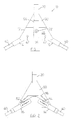
- is a front view of the wheel clamp in its operational condition;
- Fig.2
- is a rear view of the wheel clamp in its operational condition;
- Fig.3
- is a view as Fig. 1, but with some of the hidden components shown in dotted lines;
- Fig. 4
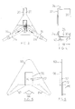
- is a side view of the wheel clamp in its operational condition;
- Fig.5
- is a front view of the cover plate of the clamp, with the hidden components shown in dotted outline;
- Fig.6
- is a side view of the cover plate;
- Fig. 7
- is a side view of part of the top arm of the clamp;
- Fig.8
- is a plan view of the radial portion of the top arm;
- Fig.9
- is a plan view of part of the axial portion of the top arm;
- Fig. 10
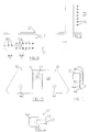
- is a front view of the clamp body;
- Fig. 11
- is a side view of the clamp body;
- Fig.12
- is a side view of a pivot peg of the clamp body;
- Fig. 13
- is a side view of part of a bottom arm of the clamp;
- Fig. 14
- is a plan view of the radial portion of a bottom arm;
- Fig. 15
- is a plan view of part of the axial portion of a bottom arm;
- Fig. 16
- is a side view of the remainder of the top arm and each of the bottom arms; and
- Fig.17
- is a plan view of the remainder of the arms.
- The
wheel clamp 10 comprises aclamp body 12 to which two (bottom)arms arm 20 is securable to the clamp body by way of a lock (not shown) located inlock housing 22. - As better seen in Fig.4, the
arms radial portion 24, anaxial portion 26 and a return radial portion 30. The top arm includes aradial portion 32, anaxial portion 34 and a return radial portion 36. It will be understood that in use theradial portions axial portions - Each of the
bottom arms respective extension piece 40, which projects from the axial portion of the respective arm. The extension piece is designed to engage a part of the bodywork of the vehicle in the event that the wheel is rotated with the wheel clamp in place. - The
bottom arms clamp body 12 by way of respective pivot pegs 42 (see also Figs. 11 and 12). Eachpivot peg 42 comprises aboss 44 and ashaft 46, theshaft 46 occupying a hole in theplate 48 which forms a part of theclamp body 12. Theshaft 46 has a counter-bore 50 formed therein, which counter-bore is threaded. As shown in Fig. 14, theradial portion 24 of eacharm holes 52 formed therein, which holes are sized to be a sliding fit over theshaft 46 of thepivot peg 42. The length of theshaft 46 which projects from theplate 48 is slightly greater than the thickness of theradial portion 24 of thearm counter-bore 50 it can secure thearm clamp body 12 but allow relative pivoting thereof. - The ability of the
arms bottom arms wheel clamp 10 to a vehicle wheel thetop arm 20 is removed, and thebottom arms arms clamp body 12 close to the ground. When the return radial portions have passed behind the wheel theclamp body 12 can be lifted, whereupon theaxial portions 26 of thearms arms - The
top arm 20 is secured to a cover plate 60 (see also Figs. 5 and 6) by way of screws or bolts passing through theholes 62 in thecover plate 60 and into two of the series of spaced threaded mounting holes 64 (Fig.8) in theradial portion 32 of thearm 20. Thecover plate 60 carries achannel section 66 through which theradial portion 32 passes, and which channel section obscures the screws or bolts and so reduces the likelihood that these can be removed by drilling or the like. - In the operative condition of the wheel clamp as shown in Figs. 1-3, the
top arm 20 andcover plate 60 have been moved (together) to lie adjacent theclamp body 12. In particular, the top edge 70 (Fig. 11) of theclamp body 12 lies against (or at least very close to) the step 72 (Fig.6) in thecover plate 60. In this condition thechannel section 66 which is carried by thecover plate 12 lies close to a similar channel section 76 (see also Figs. 10 and 11) of theclamp body 12. Theradial portion 32 of thetop arm 20 passes into thechannel section 76, and the row of lock apertures 80 (Fig.8) pass beneath thelock housing 22. A conventional lock (not shown) can be located within thelock housing 22 and carry a movable projection which, when the lock is activated, can locate within a chosen one of thelock apertures 80, preventing separation of the top arm 20 (and hence also the cover plate 60) from theclamp body 12. - As shown in Fig.5, the bottom edge of the
cover plate 60 is not flat, but includes twowall members - As seen in the rear view of Fig.2, in the operative (assembled) condition the
wall members radial portions 24 of therespective arm members wall members respective arm arm 14 either clockwise or anti-clockwise from the position shown will result in the arm engaging a part of thewall member 84, so that the pivoting of the arm members is limited and thearms top arm 20, and its sliding relationship with the channel section 76 (and also the relationship of thetop edge 70 of theclamp body 12 with the step 72) maintain the angular relationship between theclamp body 12 and thetop arm 20, so that the angular relationship between all of thearms - It will be seen from Figs. 2 and 6 that the
cover plate 60 also carries a strengtheningplate 86, which serves to reduce or eliminate the possibility of thecover plate 60 being bent or deformed by a person intent on disabling the fitted clamp. - It will be seen from Fig.8 that the spacing s between adjacent mounting
holes 64 matches the spacing s betweenadjacent lock apertures 80. This is necessary so that in the operative condition of the clamp therespective channel sections top edge 70 of theclamp body 12 and thestep 72 can remain consistent, for any adjustment position of thetop arm 20. - It will be understood from Fig.8 that six adjustment positions are available for the bolts or screws securing the
top arm 20 to thecover plate 60. This gives six possible effective lengths for the radial portion of thetop arm 20. The spacing s in this embodiment is 20 mm, and this sets the separation between adjacent adjustment positions. The spacing s could be smaller or larger as desired, but 20 mm is believed to be an appropriate separation between adjacent adjustment positions. Also, in other embodiments more or fewer than six adjustment positions may be provided, as desired or required. - As seen in Fig. 14, there are also six adjustment positions for the
bottom arms adjustment apertures - As shown in Fig.4, the
axial portion radial portion 24 of anarm - As shown in Fig.17, each L-piece includes two
apertures 92. As shown in Figs.9 and 15, the remainder of theaxial portion axial portion 26 of thearms apertures 92 and into theapertures 96 to secure the L-piece to the remainder of the arm. The distance D between theapertures 92 is an exact multiple of the distance d between the apertures 96 (in this embodiment D = 2d). This arrangement provides five adjustment positions for the axial portions of the arms, though in other emboments more or fewer adjustment positions are possible. The distance d can be the same as the spacing s if desired, so that adjustment in the radial and axial portions can take place in similar increments, but this need not be so.
Claims (10)
- Wheel clamp (10) having three arms (14, 16, 20), each of the arms including a radial part (24, 32) and an axial part (26, 34), at least one of the arms including a return radial part (30, 36), two of the arms (14, 16) being mounted upon a clamp body (12) and having an adjustable radial part (24), the other of the arms (20) being securable to the clamp body in a number of predetermined positions, characterised by means (82, 84) to maintain the relative angular orientation of said two of the arms.
- Wheel clamp according to claim 1 in which said two of the arms (14, 16) are pivotably mounted to the clamp body (12), and in which the means to maintain the relative angular orientation of said two of the arms (82, 84) can be moved relative to the clamp body to a position in which pivoting movement of the arms is substantially prevented.
- Wheel clamp according to claim 1 or claim 2 in which the means to maintain the relative angular orientation of said two of the arms is at least one wall member (82, 84).
- Wheel clamp according to claim 3 in which said at least one wall member (82, 84) is connected to the other of the arms (20).
- Wheel clamp according to claim 3 or claim 4 in which said at least one wall member (82, 84) comprises an edge of a cover plate (60) connected to the other of the arms (20).
- Wheel clamp according to claim 5 in which the cover plate (60) and clamp body (12) are together adapted to obscure a significant part of a wheel to which the wheel clamp (10) is fitted.
- Wheel clamp according to claim 5 or claim 6 in which said cover plate (60) has a first portion which lies behind a part of the clamp body (12) in the assembled wheel clamp, and a second portion which does not lie behind a part of the clamp body in the assembled wheel clamp, said at least one wall member (82, 84) being an edge of said first portion of the cover plate.
- Wheel clamp according to any one of claims 3-7 in which said at least one wall member has two surfaces (82, 84) set at the relative angle (α) determined for said two of the arms (14, 16).
- Wheel clamp according to any one of claims 5-7 in which the cover plate (60) can be connected to the other of the arms (20) in a number of spaced positions.
- Wheel clamp according to any one of claims 1-9 in which said other of the arms is slidably mountable to the clamp body by way of a channel section carried by the clamp body.
Applications Claiming Priority (2)
| Application Number | Priority Date | Filing Date | Title |
|---|---|---|---|
| GB0204844 | 2002-03-01 | ||
| GBGB0204844.5A GB0204844D0 (en) | 2002-03-01 | 2002-03-01 | Wheel clamp |
Publications (2)
| Publication Number | Publication Date |
|---|---|
| EP1340658A1 true EP1340658A1 (en) | 2003-09-03 |
| EP1340658B1 EP1340658B1 (en) | 2006-11-29 |
Family
ID=9932079
Family Applications (1)
| Application Number | Title | Priority Date | Filing Date |
|---|---|---|---|
| EP03251229A Expired - Lifetime EP1340658B1 (en) | 2002-03-01 | 2003-02-28 | Wheel clamp |
Country Status (4)
| Country | Link |
|---|---|
| EP (1) | EP1340658B1 (en) |
| AT (1) | ATE346777T1 (en) |
| DE (1) | DE60309944D1 (en) |
| GB (1) | GB0204844D0 (en) |
Cited By (3)
| Publication number | Priority date | Publication date | Assignee | Title |
|---|---|---|---|---|
| GB2419858A (en) * | 2004-11-04 | 2006-05-10 | Philip Denman | An adjustable clamp for a vehicle wheel |
| EP2404790A1 (en) | 2010-07-08 | 2012-01-11 | Maypole Limited | Wheel clamp and methods of use |
| EP3501915A1 (en) | 2017-12-20 | 2019-06-26 | Maypole Limited | Wheel clamp and method of fitment |
Citations (6)
| Publication number | Priority date | Publication date | Assignee | Title |
|---|---|---|---|---|
| GB2124566A (en) * | 1982-06-22 | 1984-02-22 | John Robert Tillard | Immobilising vehicles |
| US4854144A (en) * | 1987-08-17 | 1989-08-08 | Double Helix Enterprises | Vehicle immobilization device |
| GB2273084A (en) * | 1992-12-02 | 1994-06-08 | John Leonard Barker | Wheel clamp |
| US5333477A (en) * | 1993-07-20 | 1994-08-02 | Phillip Davis | Vehicle parking boot |
| GB2279632A (en) * | 1993-07-02 | 1995-01-11 | Grayspeed Leisure Products Lim | Wheel clamp |
| US5706682A (en) * | 1994-10-31 | 1998-01-13 | Barker; J. W. | Vehicle safety and security device removably mountable to surround a vehicle tire |
-
2002
- 2002-03-01 GB GBGB0204844.5A patent/GB0204844D0/en not_active Ceased
-
2003
- 2003-02-28 DE DE60309944T patent/DE60309944D1/en not_active Expired - Lifetime
- 2003-02-28 AT AT03251229T patent/ATE346777T1/en not_active IP Right Cessation
- 2003-02-28 EP EP03251229A patent/EP1340658B1/en not_active Expired - Lifetime
Patent Citations (6)
| Publication number | Priority date | Publication date | Assignee | Title |
|---|---|---|---|---|
| GB2124566A (en) * | 1982-06-22 | 1984-02-22 | John Robert Tillard | Immobilising vehicles |
| US4854144A (en) * | 1987-08-17 | 1989-08-08 | Double Helix Enterprises | Vehicle immobilization device |
| GB2273084A (en) * | 1992-12-02 | 1994-06-08 | John Leonard Barker | Wheel clamp |
| GB2279632A (en) * | 1993-07-02 | 1995-01-11 | Grayspeed Leisure Products Lim | Wheel clamp |
| US5333477A (en) * | 1993-07-20 | 1994-08-02 | Phillip Davis | Vehicle parking boot |
| US5706682A (en) * | 1994-10-31 | 1998-01-13 | Barker; J. W. | Vehicle safety and security device removably mountable to surround a vehicle tire |
Cited By (3)
| Publication number | Priority date | Publication date | Assignee | Title |
|---|---|---|---|---|
| GB2419858A (en) * | 2004-11-04 | 2006-05-10 | Philip Denman | An adjustable clamp for a vehicle wheel |
| EP2404790A1 (en) | 2010-07-08 | 2012-01-11 | Maypole Limited | Wheel clamp and methods of use |
| EP3501915A1 (en) | 2017-12-20 | 2019-06-26 | Maypole Limited | Wheel clamp and method of fitment |
Also Published As
| Publication number | Publication date |
|---|---|
| DE60309944D1 (en) | 2007-01-11 |
| EP1340658B1 (en) | 2006-11-29 |
| ATE346777T1 (en) | 2006-12-15 |
| GB0204844D0 (en) | 2002-04-17 |
Similar Documents
| Publication | Publication Date | Title |
|---|---|---|
| US5333477A (en) | Vehicle parking boot | |
| US4913265A (en) | Vehicle immobilizing device | |
| US7107802B2 (en) | Wheel immobilizer | |
| US20070245783A1 (en) | Adjustable Two-Piece Vehicle Immobilizer | |
| US5461891A (en) | Apparatus for secure positioning over and around a steering wheel and steering column to prevent theft | |
| US5463885A (en) | Trailer wheel lock | |
| US6460385B1 (en) | Column lock device | |
| EP1340658B1 (en) | Wheel clamp | |
| US5996721A (en) | Steering wheel and air bag protection device | |
| AU2019236681B2 (en) | A security system | |
| GB2269348A (en) | Anti-theft device | |
| US20090031765A1 (en) | Multi-function steering wheel lock | |
| US5737949A (en) | Automobile anti-theft device | |
| GB2483109A (en) | A wheel clamp for a vehicle | |
| WO1996021586A9 (en) | Automobile anti-theft device | |
| GB2283952A (en) | Anti-theft device for vehicles | |
| GB2279632A (en) | Wheel clamp | |
| KR200394907Y1 (en) | Vehicle Immobilization Device | |
| EP1705084B1 (en) | Antitheft device for cars | |
| EP0989037A1 (en) | Vehicle anti-theft device in the form of a steering wheel cover adaptable to a steering wheel with play | |
| CN2133489Y (en) | car steering wheel lock | |
| CA2466693C (en) | Wheel immobilizer | |
| JPH07267001A (en) | Anti-theft device of on-vehicle sound equipment | |
| US20050166646A1 (en) | Method and apparatus for securing an object to a vehicle | |
| WO1994012371A1 (en) | Portable anti-theft device for vehicles |
Legal Events
| Date | Code | Title | Description |
|---|---|---|---|
| PUAI | Public reference made under article 153(3) epc to a published international application that has entered the european phase |
Free format text: ORIGINAL CODE: 0009012 |
|
| AK | Designated contracting states |
Kind code of ref document: A1 Designated state(s): AT BE BG CH CY CZ DE DK EE ES FI FR GB GR HU IE IT LI LU MC NL PT SE SI SK TR |
|
| AX | Request for extension of the european patent |
Extension state: AL LT LV MK RO |
|
| 17P | Request for examination filed |
Effective date: 20040303 |
|
| AKX | Designation fees paid |
Designated state(s): AT BE BG CH CY CZ DE DK EE ES FI FR GB GR HU IE IT LI LU MC NL PT SE SI SK TR |
|
| 17Q | First examination report despatched |
Effective date: 20040715 |
|
| RAP1 | Party data changed (applicant data changed or rights of an application transferred) |
Owner name: SAS MANUFACTURING LIMITED |
|
| GRAP | Despatch of communication of intention to grant a patent |
Free format text: ORIGINAL CODE: EPIDOSNIGR1 |
|
| GRAS | Grant fee paid |
Free format text: ORIGINAL CODE: EPIDOSNIGR3 |
|
| GRAA | (expected) grant |
Free format text: ORIGINAL CODE: 0009210 |
|
| AK | Designated contracting states |
Kind code of ref document: B1 Designated state(s): AT BE BG CH CY CZ DE DK EE ES FI FR GB GR HU IE IT LI LU MC NL PT SE SI SK TR |
|
| PG25 | Lapsed in a contracting state [announced via postgrant information from national office to epo] |
Ref country code: IT Free format text: LAPSE BECAUSE OF FAILURE TO SUBMIT A TRANSLATION OF THE DESCRIPTION OR TO PAY THE FEE WITHIN THE PRESCRIBED TIME-LIMIT;WARNING: LAPSES OF ITALIAN PATENTS WITH EFFECTIVE DATE BEFORE 2007 MAY HAVE OCCURRED AT ANY TIME BEFORE 2007. THE CORRECT EFFECTIVE DATE MAY BE DIFFERENT FROM THE ONE RECORDED. Effective date: 20061129 Ref country code: AT Free format text: LAPSE BECAUSE OF FAILURE TO SUBMIT A TRANSLATION OF THE DESCRIPTION OR TO PAY THE FEE WITHIN THE PRESCRIBED TIME-LIMIT Effective date: 20061129 Ref country code: BE Free format text: LAPSE BECAUSE OF FAILURE TO SUBMIT A TRANSLATION OF THE DESCRIPTION OR TO PAY THE FEE WITHIN THE PRESCRIBED TIME-LIMIT Effective date: 20061129 Ref country code: SK Free format text: LAPSE BECAUSE OF FAILURE TO SUBMIT A TRANSLATION OF THE DESCRIPTION OR TO PAY THE FEE WITHIN THE PRESCRIBED TIME-LIMIT Effective date: 20061129 Ref country code: FI Free format text: LAPSE BECAUSE OF FAILURE TO SUBMIT A TRANSLATION OF THE DESCRIPTION OR TO PAY THE FEE WITHIN THE PRESCRIBED TIME-LIMIT Effective date: 20061129 Ref country code: NL Free format text: LAPSE BECAUSE OF FAILURE TO SUBMIT A TRANSLATION OF THE DESCRIPTION OR TO PAY THE FEE WITHIN THE PRESCRIBED TIME-LIMIT Effective date: 20061129 Ref country code: CZ Free format text: LAPSE BECAUSE OF FAILURE TO SUBMIT A TRANSLATION OF THE DESCRIPTION OR TO PAY THE FEE WITHIN THE PRESCRIBED TIME-LIMIT Effective date: 20061129 Ref country code: CH Free format text: LAPSE BECAUSE OF FAILURE TO SUBMIT A TRANSLATION OF THE DESCRIPTION OR TO PAY THE FEE WITHIN THE PRESCRIBED TIME-LIMIT Effective date: 20061129 Ref country code: LI Free format text: LAPSE BECAUSE OF FAILURE TO SUBMIT A TRANSLATION OF THE DESCRIPTION OR TO PAY THE FEE WITHIN THE PRESCRIBED TIME-LIMIT Effective date: 20061129 Ref country code: SI Free format text: LAPSE BECAUSE OF FAILURE TO SUBMIT A TRANSLATION OF THE DESCRIPTION OR TO PAY THE FEE WITHIN THE PRESCRIBED TIME-LIMIT Effective date: 20061129 |
|
| REG | Reference to a national code |
Ref country code: GB Ref legal event code: FG4D |
|
| REG | Reference to a national code |
Ref country code: CH Ref legal event code: EP |
|
| REG | Reference to a national code |
Ref country code: IE Ref legal event code: FG4D |
|
| REF | Corresponds to: |
Ref document number: 60309944 Country of ref document: DE Date of ref document: 20070111 Kind code of ref document: P |
|
| PG25 | Lapsed in a contracting state [announced via postgrant information from national office to epo] |
Ref country code: SE Free format text: LAPSE BECAUSE OF FAILURE TO SUBMIT A TRANSLATION OF THE DESCRIPTION OR TO PAY THE FEE WITHIN THE PRESCRIBED TIME-LIMIT Effective date: 20070228 Ref country code: MC Free format text: LAPSE BECAUSE OF NON-PAYMENT OF DUE FEES Effective date: 20070228 Ref country code: BG Free format text: LAPSE BECAUSE OF FAILURE TO SUBMIT A TRANSLATION OF THE DESCRIPTION OR TO PAY THE FEE WITHIN THE PRESCRIBED TIME-LIMIT Effective date: 20070228 Ref country code: DK Free format text: LAPSE BECAUSE OF FAILURE TO SUBMIT A TRANSLATION OF THE DESCRIPTION OR TO PAY THE FEE WITHIN THE PRESCRIBED TIME-LIMIT Effective date: 20070228 |
|
| PG25 | Lapsed in a contracting state [announced via postgrant information from national office to epo] |
Ref country code: DE Free format text: LAPSE BECAUSE OF FAILURE TO SUBMIT A TRANSLATION OF THE DESCRIPTION OR TO PAY THE FEE WITHIN THE PRESCRIBED TIME-LIMIT Effective date: 20070301 |
|
| PG25 | Lapsed in a contracting state [announced via postgrant information from national office to epo] |
Ref country code: ES Free format text: LAPSE BECAUSE OF FAILURE TO SUBMIT A TRANSLATION OF THE DESCRIPTION OR TO PAY THE FEE WITHIN THE PRESCRIBED TIME-LIMIT Effective date: 20070312 |
|
| PG25 | Lapsed in a contracting state [announced via postgrant information from national office to epo] |
Ref country code: PT Free format text: LAPSE BECAUSE OF FAILURE TO SUBMIT A TRANSLATION OF THE DESCRIPTION OR TO PAY THE FEE WITHIN THE PRESCRIBED TIME-LIMIT Effective date: 20070430 |
|
| NLV1 | Nl: lapsed or annulled due to failure to fulfill the requirements of art. 29p and 29m of the patents act | ||
| REG | Reference to a national code |
Ref country code: CH Ref legal event code: PL |
|
| EN | Fr: translation not filed | ||
| REG | Reference to a national code |
Ref country code: GB Ref legal event code: 732E |
|
| PLBE | No opposition filed within time limit |
Free format text: ORIGINAL CODE: 0009261 |
|
| STAA | Information on the status of an ep patent application or granted ep patent |
Free format text: STATUS: NO OPPOSITION FILED WITHIN TIME LIMIT |
|
| 26N | No opposition filed |
Effective date: 20070830 |
|
| PG25 | Lapsed in a contracting state [announced via postgrant information from national office to epo] |
Ref country code: GR Free format text: LAPSE BECAUSE OF FAILURE TO SUBMIT A TRANSLATION OF THE DESCRIPTION OR TO PAY THE FEE WITHIN THE PRESCRIBED TIME-LIMIT Effective date: 20070301 Ref country code: FR Free format text: LAPSE BECAUSE OF FAILURE TO SUBMIT A TRANSLATION OF THE DESCRIPTION OR TO PAY THE FEE WITHIN THE PRESCRIBED TIME-LIMIT Effective date: 20070720 |
|
| PG25 | Lapsed in a contracting state [announced via postgrant information from national office to epo] |
Ref country code: FR Free format text: LAPSE BECAUSE OF FAILURE TO SUBMIT A TRANSLATION OF THE DESCRIPTION OR TO PAY THE FEE WITHIN THE PRESCRIBED TIME-LIMIT Effective date: 20061129 |
|
| PG25 | Lapsed in a contracting state [announced via postgrant information from national office to epo] |
Ref country code: EE Free format text: LAPSE BECAUSE OF FAILURE TO SUBMIT A TRANSLATION OF THE DESCRIPTION OR TO PAY THE FEE WITHIN THE PRESCRIBED TIME-LIMIT Effective date: 20061129 |
|
| PG25 | Lapsed in a contracting state [announced via postgrant information from national office to epo] |
Ref country code: LU Free format text: LAPSE BECAUSE OF NON-PAYMENT OF DUE FEES Effective date: 20070228 Ref country code: CY Free format text: LAPSE BECAUSE OF FAILURE TO SUBMIT A TRANSLATION OF THE DESCRIPTION OR TO PAY THE FEE WITHIN THE PRESCRIBED TIME-LIMIT Effective date: 20061129 |
|
| PG25 | Lapsed in a contracting state [announced via postgrant information from national office to epo] |
Ref country code: HU Free format text: LAPSE BECAUSE OF FAILURE TO SUBMIT A TRANSLATION OF THE DESCRIPTION OR TO PAY THE FEE WITHIN THE PRESCRIBED TIME-LIMIT Effective date: 20070530 Ref country code: TR Free format text: LAPSE BECAUSE OF FAILURE TO SUBMIT A TRANSLATION OF THE DESCRIPTION OR TO PAY THE FEE WITHIN THE PRESCRIBED TIME-LIMIT Effective date: 20061129 |
|
| PGFP | Annual fee paid to national office [announced via postgrant information from national office to epo] |
Ref country code: IE Payment date: 20220106 Year of fee payment: 20 Ref country code: GB Payment date: 20220110 Year of fee payment: 20 |
|
| REG | Reference to a national code |
Ref country code: GB Ref legal event code: PE20 Expiry date: 20230227 |
|
| REG | Reference to a national code |
Ref country code: IE Ref legal event code: MK9A |
|
| PG25 | Lapsed in a contracting state [announced via postgrant information from national office to epo] |
Ref country code: IE Free format text: LAPSE BECAUSE OF EXPIRATION OF PROTECTION Effective date: 20230228 |
|
| PG25 | Lapsed in a contracting state [announced via postgrant information from national office to epo] |
Ref country code: GB Free format text: LAPSE BECAUSE OF EXPIRATION OF PROTECTION Effective date: 20230227 |