EP1339307B1 - A coupling device for a detachable connection of a suction hose to a vacuum cleaner housing - Google Patents
A coupling device for a detachable connection of a suction hose to a vacuum cleaner housing Download PDFInfo
- Publication number
- EP1339307B1 EP1339307B1 EP01998255A EP01998255A EP1339307B1 EP 1339307 B1 EP1339307 B1 EP 1339307B1 EP 01998255 A EP01998255 A EP 01998255A EP 01998255 A EP01998255 A EP 01998255A EP 1339307 B1 EP1339307 B1 EP 1339307B1
- Authority
- EP
- European Patent Office
- Prior art keywords
- connecting piece
- suction hose
- coupling device
- socket
- vacuum cleaner
- Prior art date
- Legal status (The legal status is an assumption and is not a legal conclusion. Google has not performed a legal analysis and makes no representation as to the accuracy of the status listed.)
- Revoked
Links
- 230000008878 coupling Effects 0.000 title claims abstract description 26
- 238000010168 coupling process Methods 0.000 title claims abstract description 26
- 238000005859 coupling reaction Methods 0.000 title claims abstract description 26
- 238000007789 sealing Methods 0.000 claims abstract description 11
- 238000004519 manufacturing process Methods 0.000 abstract description 6
- 238000000465 moulding Methods 0.000 description 5
- 239000000428 dust Substances 0.000 description 4
- 238000001746 injection moulding Methods 0.000 description 3
- 230000009471 action Effects 0.000 description 1
- 238000005452 bending Methods 0.000 description 1
- 238000006073 displacement reaction Methods 0.000 description 1
- 238000001914 filtration Methods 0.000 description 1
- 238000000034 method Methods 0.000 description 1
- 239000002245 particle Substances 0.000 description 1
- 238000003825 pressing Methods 0.000 description 1
- 230000008569 process Effects 0.000 description 1
- 230000009467 reduction Effects 0.000 description 1
- 239000012815 thermoplastic material Substances 0.000 description 1
Images


Classifications
-
- A—HUMAN NECESSITIES
- A47—FURNITURE; DOMESTIC ARTICLES OR APPLIANCES; COFFEE MILLS; SPICE MILLS; SUCTION CLEANERS IN GENERAL
- A47L—DOMESTIC WASHING OR CLEANING; SUCTION CLEANERS IN GENERAL
- A47L9/00—Details or accessories of suction cleaners, e.g. mechanical means for controlling the suction or for effecting pulsating action; Storing devices specially adapted to suction cleaners or parts thereof; Carrying-vehicles specially adapted for suction cleaners
- A47L9/24—Hoses or pipes; Hose or pipe couplings
- A47L9/242—Hose or pipe couplings
-
- F—MECHANICAL ENGINEERING; LIGHTING; HEATING; WEAPONS; BLASTING
- F16—ENGINEERING ELEMENTS AND UNITS; GENERAL MEASURES FOR PRODUCING AND MAINTAINING EFFECTIVE FUNCTIONING OF MACHINES OR INSTALLATIONS; THERMAL INSULATION IN GENERAL
- F16L—PIPES; JOINTS OR FITTINGS FOR PIPES; SUPPORTS FOR PIPES, CABLES OR PROTECTIVE TUBING; MEANS FOR THERMAL INSULATION IN GENERAL
- F16L37/00—Couplings of the quick-acting type
- F16L37/08—Couplings of the quick-acting type in which the connection between abutting or axially overlapping ends is maintained by locking members
- F16L37/084—Couplings of the quick-acting type in which the connection between abutting or axially overlapping ends is maintained by locking members combined with automatic locking
- F16L37/098—Couplings of the quick-acting type in which the connection between abutting or axially overlapping ends is maintained by locking members combined with automatic locking by means of flexible hooks
Definitions
- the present invention relates to a coupling device for a detachable connection of a suction hose to the inlet opening in a vacuum cleaner housing, said inlet opening including a socket for receiving a tube connecting piece mounted on the suction hose, said connecting piece including latch means that are realisably connected to the socket and sealing means interacting with the socket.
- a coupling device of this kind is known from EP-A-0 328 494 which corrresponds to the preamble of claim 1.
- This coupling device consists of a latch that is fixed to a connecting sleeve that engages corresponding receiving means in the vacuum cleaner housing.
- the suction hose is fixed to a connecting piece that is received in a cylindrical socket of the housing.
- the sleeve is secured to a cylindrical tube connecting piece so that the hose and the connecting piece is rotatable in the sleeve.
- the connection piece is provided with a sealing ring that engages the inner cylindrical surface of the socket for providing an air tight seal.
- this coupling device has some drawbacks both in the production phase and the during the use of the vacuum cleaner.
- the receiving means for receiving the latch in the housing is relatively difficult and expensive to manufacture.
- the coupling device may be flexed out of alignment causing a puncture of the air tight sealing.
- the vacuum cleaner is often being pulled at the suction hose by the user. The pulling action is often inclined as the vacuum cleaner is pulled around corners, etc. This flexes the coupling device in the socket and the coupling between the hose and the housing is no longer air tight.
- the object by the present invention is to provide an improved coupling device that is more simple to manufacture and secures an air tight snap fit connection between the hose and the housing of the vacuum cleaner.
- a coupling device of the initially mentioned kind wherein the connecting piece includes a plurality of symmetrically arranged resilient latches and that said latches are realisably connected to latch receiving means that are formed in an external wall member integrally formed on the housing.
- a snap fit connection between the suction hose and the tank element of the housing is provided where the connecting piece of the hose connects to the housing without extra connection parts.
- the number of parts involved in a coupling device according to the invention is reduced making the coupling device cheaper and quicker to manufacture.
- By providing a plurality of latches arranged symmetrically around the tubular connection piece an air tight fit is ensured also when the suction hose is being pulled in an angle.
- the feature of hooking the connecting piece to an external wall member outside the housing wall means that there is no hole through to the dust compartment of the vacuum cleaner. Normally, an extra element must be used for sealing the holes or more complicated moulding tool elements are needed, such as collapsible cores.
- the absence of holes in the dust compartment contributes to a simple design and to ensuring an air tight fit of the suction hose in the vacuum cleaner housing.
- the external wall member is integrally formed in the housing, with means that it is produced together with the housing in a single injection moulding process. It also allows for a more simple moulding process, since no collapsible core is needed.
- the holes for the snap can be made with the same slide moulding part of the moulding tool that makes the hole for the inlet/socket. All other parts are made with normal parting of the tool. This allows for the use of a cheaper injection moulding tool and a more simple moulding machine may be used in comparison with the known coupling device, just as the run-in time is shorter, the cycle time is slightly shorter and the operation is more fail safe in comparison.
- the sealing means include a conical outer surface on the connecting piece and a correspondingly shaped conical surface in the socket for receiving said conical outer surface.
- the conic surfaces of the tank housing and the connecting piece provide the air tight sealing since the suction hose and the connected housing is under partial vacuum and the two parts are sucked together.
- the conic surfaces also ensures an alignment of the two parts of the coupling device preventing the problems associated with the angled pulling of the suction hose.
- the connecting piece is mounted to the suction hose at one first end and provided with side openings with a reflection plate at the opposite end.
- the connecting piece is provided with two resilient latches. This allows for a particular simple device coupling device in order to obtain the advantages explained above.
- FIG 1 a schematic cross-section side view of a vacuum cleaner is shown.
- the vacuum cleaner comprises a housing with three elements: a tank element 1, a middle chassis element 2 and a top cover element 3.
- a suction hose 4 is connected to the tank element 1 via a coupling device (see figs. 2 to 4).
- an air flow generator 5 is provided in the chassis element 2 .
- dust collection means (not shown) may be provided and the tank element 1 is also fitted with wheels 18.
- the interior space of the tank element 1 is under partial vacuum as the air flow generator 5 sucks air out of the tank compartment and blows into the second air compartment under the top cover 3.
- the air is led through an air exhaust system 6 that may include noise reduction means, air filtration means etc.
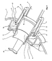
- FIG 2 to 4 a portion of the vacuum cleaner housing 1 is shown which has a socket 8 and a connecting piece 7.
- the suction hose 4 is fixed to a connecting piece 7 that is realisably connected to the socket 8.
- the hose 4 may be fixed to the connecting piece 7 by bonding, by use of an expanding ring or in any other suitable manner.
- the connecting piece 7 is inserted into the socket 8 (in the figures 2-4 the assembled coupling is shown).
- the connecting piece 7 is provided with two symmetrically arranged resilient latches 9, 10 with hooks 11, 13 that engages corresponding receiving means 12, 14; 20, 21.
- the receiving means include cavities 12, 14 between the external wall member 15 (see fig. 3) integrally formed on the outside of the genuine wall housing 1.
- the latches 9, 10 are inserted through openings 20, 21 in the external wall member 15 whereby the latch hooks 11, 13 enters the cavities 12, 14 behind the external wall member 15.
- the connecting piece 7 is releasably connected to the housing 1 in a non-rotatable manner that provides a reliable connection as bending forces applied to the connecting piece 7 due to an angular pulling of the suction hose 4 does not result in a displacement of the connecting piece 7 in the socket 8.
- the socket 8 is provided with a conic surface 16 that engages with a corresponding conic surface 17 on the connecting piece 7.
- the connection is provided with an air tight seal in particular when partial vacuum is established in the tank housing 1.
- the hose 4 may easily be connected and disconnected from the socket 8 and the external wall member 15 of the housing 1 by pressing together the latches 9, 10, situated symmetrically on each side of the hose 4, an inserting or withdrawing the connecting piece 7 from the socket 8.
- a coupling device may be obtained with relatively few parts in a thermoplastic material and that these parts are designed in geometric shapes being adapted for production by a relatively simple injection moulding process.
Landscapes
- Engineering & Computer Science (AREA)
- Mechanical Engineering (AREA)
- Electric Vacuum Cleaner (AREA)
- Nozzles For Electric Vacuum Cleaners (AREA)
- Quick-Acting Or Multi-Walled Pipe Joints (AREA)
Abstract
Description
- The present invention relates to a coupling device for a detachable connection of a suction hose to the inlet opening in a vacuum cleaner housing, said inlet opening including a socket for receiving a tube connecting piece mounted on the suction hose, said connecting piece including latch means that are realisably connected to the socket and sealing means interacting with the socket.
- A coupling device of this kind is known from EP-A-0 328 494 which corrresponds to the preamble of
claim 1. This coupling device consists of a latch that is fixed to a connecting sleeve that engages corresponding receiving means in the vacuum cleaner housing. The suction hose is fixed to a connecting piece that is received in a cylindrical socket of the housing. The sleeve is secured to a cylindrical tube connecting piece so that the hose and the connecting piece is rotatable in the sleeve. The connection piece is provided with a sealing ring that engages the inner cylindrical surface of the socket for providing an air tight seal. Hereby a snap fit connection between the suction hose and the vacuum cleaner housing is provided. However this coupling device has some drawbacks both in the production phase and the during the use of the vacuum cleaner. - In particular the receiving means for receiving the latch in the housing is relatively difficult and expensive to manufacture. Another drawback is that the coupling device may be flexed out of alignment causing a puncture of the air tight sealing. The vacuum cleaner is often being pulled at the suction hose by the user. The pulling action is often inclined as the vacuum cleaner is pulled around corners, etc. This flexes the coupling device in the socket and the coupling between the hose and the housing is no longer air tight.
- Thus, the object by the present invention is to provide an improved coupling device that is more simple to manufacture and secures an air tight snap fit connection between the hose and the housing of the vacuum cleaner.
- This object is achieved by a coupling device of the initially mentioned kind, wherein the connecting piece includes a plurality of symmetrically arranged resilient latches and that said latches are realisably connected to latch receiving means that are formed in an external wall member integrally formed on the housing.
- Hereby, a snap fit connection between the suction hose and the tank element of the housing is provided where the connecting piece of the hose connects to the housing without extra connection parts. Thus, the number of parts involved in a coupling device according to the invention is reduced making the coupling device cheaper and quicker to manufacture. By providing a plurality of latches arranged symmetrically around the tubular connection piece, an air tight fit is ensured also when the suction hose is being pulled in an angle. The feature of hooking the connecting piece to an external wall member outside the housing wall, means that there is no hole through to the dust compartment of the vacuum cleaner. Normally, an extra element must be used for sealing the holes or more complicated moulding tool elements are needed, such as collapsible cores. The absence of holes in the dust compartment contributes to a simple design and to ensuring an air tight fit of the suction hose in the vacuum cleaner housing. The external wall member is integrally formed in the housing, with means that it is produced together with the housing in a single injection moulding process. It also allows for a more simple moulding process, since no collapsible core is needed. The holes for the snap can be made with the same slide moulding part of the moulding tool that makes the hole for the inlet/socket. All other parts are made with normal parting of the tool. This allows for the use of a cheaper injection moulding tool and a more simple moulding machine may be used in comparison with the known coupling device, just as the run-in time is shorter, the cycle time is slightly shorter and the operation is more fail safe in comparison.
- In the preferred embodiment of a coupling device according to the invention, the sealing means include a conical outer surface on the connecting piece and a correspondingly shaped conical surface in the socket for receiving said conical outer surface. Hereby, the need for a separate sealing ring is eliminated. The conic surfaces of the tank housing and the connecting piece provide the air tight sealing since the suction hose and the connected housing is under partial vacuum and the two parts are sucked together. Moreover, the conic surfaces also ensures an alignment of the two parts of the coupling device preventing the problems associated with the angled pulling of the suction hose.
- In a preferred embodiment, the connecting piece is mounted to the suction hose at one first end and provided with side openings with a reflection plate at the opposite end. By this embodiment, the particles that are sucked into the housing tank are prevented from making direct impact with the dust collection bag situated therein, whereby the risk of perforating the bag is eliminated.
- In the preferred embodiment, the connecting piece is provided with two resilient latches. This allows for a particular simple device coupling device in order to obtain the advantages explained above.
- In the following, the invention is described in detail under reference to the accompanying drawings, in which:
- fig. 1
- is a side view of a vacuum cleaner,
- fig. 2
- is an isometric top view of a coupling device according to a preferred embodiment of the invention in the assembled position,
- fig. 3
- is a bottom view of same, and
- fig. 4
- is a cross section view of the coupling device.
- In figure 1 a schematic cross-section side view of a vacuum cleaner is shown. The vacuum cleaner comprises a housing with three elements: a
tank element 1, amiddle chassis element 2 and atop cover element 3. Asuction hose 4 is connected to thetank element 1 via a coupling device (see figs. 2 to 4). In thechassis element 2 anair flow generator 5 is provided. In thetank element 1 dust collection means (not shown) may be provided and thetank element 1 is also fitted withwheels 18. The interior space of thetank element 1 is under partial vacuum as theair flow generator 5 sucks air out of the tank compartment and blows into the second air compartment under thetop cover 3. In thetop compartment 3, the air is led through anair exhaust system 6 that may include noise reduction means, air filtration means etc. - In figure 2 to 4, a portion of the
vacuum cleaner housing 1 is shown which has a socket 8 and a connectingpiece 7. Thesuction hose 4 is fixed to a connectingpiece 7 that is realisably connected to the socket 8. Thehose 4 may be fixed to the connectingpiece 7 by bonding, by use of an expanding ring or in any other suitable manner. The connectingpiece 7 is inserted into the socket 8 (in the figures 2-4 the assembled coupling is shown). The connectingpiece 7 is provided with two symmetrically arrangedresilient latches hooks corresponding receiving means cavities genuine wall housing 1. Thelatches openings external wall member 15 whereby thelatch hooks cavities external wall member 15. Hereby, the connectingpiece 7 is releasably connected to thehousing 1 in a non-rotatable manner that provides a reliable connection as bending forces applied to the connectingpiece 7 due to an angular pulling of thesuction hose 4 does not result in a displacement of the connectingpiece 7 in the socket 8. - The socket 8 is provided with a
conic surface 16 that engages with acorresponding conic surface 17 on the connectingpiece 7. Hereby, the connection is provided with an air tight seal in particular when partial vacuum is established in thetank housing 1. As theconic surfaces hose 4 may easily be connected and disconnected from the socket 8 and theexternal wall member 15 of thehousing 1 by pressing together thelatches hose 4, an inserting or withdrawing the connectingpiece 7 from the socket 8. - By the invention, it is appreciated that a coupling device may be obtained with relatively few parts in a thermoplastic material and that these parts are designed in geometric shapes being adapted for production by a relatively simple injection moulding process.
Claims (6)
- An assembly comprising a vacuum cleaner housing (1) with an inlet opening and a coupling device for a detachable connection of a suction hose (4) to the inlet opening, the coupling device comprising a tube connecting piece 7 to be fixed in use on the suction hose (4) and a socket (8) on the vacuum cleaner housing for receiving the tube connecting piece (7), said tube connecting piece (7) incuding sealing means (17) interacting with the socket (8) and latch means (9,10) that are releasably connected to the socket (8) means of latch receiving means (12,14,20,21) integrally formed with the vacuum cleaner housing (1),
characterised in that
said latch means includes a plurality of symmetrically arranged resilient latches (9,10,11,13), and that the latch receiving means (12,14,20,21) formed in a wall member (15) formed externally on the vacuum cleaner housing. - An assembly according to claim 1, wherein the sealing means include a conical outer surface (17) on the connecting piece (7) and a correspondingly shaped conical surface (16) in the socket (8) for receiving said conical outer surface (17).
- An assembly according to claim 1 or 2, wherein the tube connecting piece (7) is mounted to the suction hose (4) at one first end and is at the opposite end provided with side openings and a reflection plate (19).
- An assembly according to any of claims 1 to 3, wherein the tube connecting piece (7) is provided with two resilient latches (9,10).
- An assembly according to any of claims 1 to 4, wherein said plurality of latches (9,10) is formed integrally with said tube connecting piece (7), which is mounted directly on the suction hose (4).
- An assembly according to any of claims 1 to 4, wherein said wall member (15) extends radially to the tube connecting piece (7).
Priority Applications (1)
| Application Number | Priority Date | Filing Date | Title |
|---|---|---|---|
| EP01998255A EP1339307B1 (en) | 2000-12-01 | 2001-11-28 | A coupling device for a detachable connection of a suction hose to a vacuum cleaner housing |
Applications Claiming Priority (4)
| Application Number | Priority Date | Filing Date | Title |
|---|---|---|---|
| EP00204287A EP1210900A1 (en) | 2000-12-01 | 2000-12-01 | A coupling device for a detachable connection of a suction hose to a vaccum cleaner housing |
| EP00204287 | 2000-12-01 | ||
| EP01998255A EP1339307B1 (en) | 2000-12-01 | 2001-11-28 | A coupling device for a detachable connection of a suction hose to a vacuum cleaner housing |
| PCT/DK2001/000792 WO2002043553A1 (en) | 2000-12-01 | 2001-11-28 | A coupling device for a detachable connection of a suction hose to a vacuum cleaner housing |
Publications (2)
| Publication Number | Publication Date |
|---|---|
| EP1339307A1 EP1339307A1 (en) | 2003-09-03 |
| EP1339307B1 true EP1339307B1 (en) | 2006-06-07 |
Family
ID=8172367
Family Applications (2)
| Application Number | Title | Priority Date | Filing Date |
|---|---|---|---|
| EP00204287A Withdrawn EP1210900A1 (en) | 2000-12-01 | 2000-12-01 | A coupling device for a detachable connection of a suction hose to a vaccum cleaner housing |
| EP01998255A Revoked EP1339307B1 (en) | 2000-12-01 | 2001-11-28 | A coupling device for a detachable connection of a suction hose to a vacuum cleaner housing |
Family Applications Before (1)
| Application Number | Title | Priority Date | Filing Date |
|---|---|---|---|
| EP00204287A Withdrawn EP1210900A1 (en) | 2000-12-01 | 2000-12-01 | A coupling device for a detachable connection of a suction hose to a vaccum cleaner housing |
Country Status (6)
| Country | Link |
|---|---|
| EP (2) | EP1210900A1 (en) |
| AT (1) | ATE328528T1 (en) |
| AU (2) | AU2051802A (en) |
| DE (1) | DE60120468T2 (en) |
| DK (1) | DK1339307T3 (en) |
| WO (1) | WO2002043553A1 (en) |
Families Citing this family (3)
| Publication number | Priority date | Publication date | Assignee | Title |
|---|---|---|---|---|
| EP1491127B1 (en) | 2003-06-26 | 2012-10-17 | Black & Decker Inc. | Vacuum cleaner |
| DE102009036463B4 (en) * | 2009-07-13 | 2023-01-26 | Valeo Klimasysteme Gmbh | Vehicle air conditioning system and method for coupling a tubular element of a vehicle air conditioning system |
| DE102010039286A1 (en) | 2010-08-12 | 2012-02-16 | BSH Bosch und Siemens Hausgeräte GmbH | Connecting piece for a vacuum cleaner with locking element |
Family Cites Families (5)
| Publication number | Priority date | Publication date | Assignee | Title |
|---|---|---|---|---|
| BE562806A (en) * | 1956-11-29 | |||
| DE2850422C2 (en) * | 1978-11-21 | 1983-08-25 | Licentia Patent-Verwaltungs-Gmbh, 6000 Frankfurt | Coupling for a suction hose for connection to a vacuum cleaner |
| SE460331B (en) * | 1988-02-09 | 1989-10-02 | Electrolux Ab | COUPLING |
| US4997209A (en) * | 1989-10-26 | 1991-03-05 | H-P Products, Inc. | Universal adapter sleeve for central vacuum cleaning systems |
| DE19644337A1 (en) * | 1996-10-25 | 1998-04-30 | Valeo Gmbh | Automotive water hose to pipe fitting |
-
2000
- 2000-12-01 EP EP00204287A patent/EP1210900A1/en not_active Withdrawn
-
2001
- 2001-11-28 EP EP01998255A patent/EP1339307B1/en not_active Revoked
- 2001-11-28 AT AT01998255T patent/ATE328528T1/en not_active IP Right Cessation
- 2001-11-28 AU AU2051802A patent/AU2051802A/en active Pending
- 2001-11-28 DK DK01998255T patent/DK1339307T3/en active
- 2001-11-28 WO PCT/DK2001/000792 patent/WO2002043553A1/en not_active Ceased
- 2001-11-28 AU AU2002220518A patent/AU2002220518B2/en not_active Ceased
- 2001-11-28 DE DE60120468T patent/DE60120468T2/en not_active Expired - Lifetime
Also Published As
| Publication number | Publication date |
|---|---|
| AU2002220518B2 (en) | 2004-09-16 |
| EP1210900A1 (en) | 2002-06-05 |
| EP1339307A1 (en) | 2003-09-03 |
| DE60120468D1 (en) | 2006-07-20 |
| ATE328528T1 (en) | 2006-06-15 |
| DK1339307T3 (en) | 2006-10-02 |
| AU2051802A (en) | 2002-06-11 |
| WO2002043553A1 (en) | 2002-06-06 |
| DE60120468T2 (en) | 2007-05-16 |
Similar Documents
| Publication | Publication Date | Title |
|---|---|---|
| EP1674017B1 (en) | Dust collection unit and vacuum cleaner with the same | |
| US4941689A (en) | Coupling device for vacuum cleaner | |
| ES2291825T3 (en) | BRUSH SET WITH ROTATING LOCK UNIT FOR A VACUUM CLEANER. | |
| US20040237482A1 (en) | Cyclone dust-collecting apparatus of vacuum cleaner | |
| EP0377946A1 (en) | Improved intake seal for tank vacuum cleaner | |
| CN105380560A (en) | Electric dust collector | |
| CA2335860A1 (en) | Vacuum cleaner bag docking assembly | |
| US20110030165A1 (en) | Vacuum Cleaner | |
| JP5994536B2 (en) | Electric vacuum cleaner | |
| AU2002220518B2 (en) | A coupling device for a detachable connection of a suction hose to a vacuum cleaner housing | |
| AU2002220518A1 (en) | A coupling device for a detachable connection of a suction hose to a vacuum cleaner housing | |
| CA2261377C (en) | A connection member for a filter bag for vacuum cleaning equipment | |
| US2832612A (en) | Suction cleaner coupling with spring biased catch | |
| US8032977B2 (en) | Air moving device and method of making | |
| US7350261B2 (en) | Accessory support for an upright vacuum cleaner and accessory unit | |
| EP0534381B1 (en) | Discharge device for washing machines and the like | |
| CA2476198A1 (en) | Nozzle assembly with high efficiency agitator cavity | |
| CN220832888U (en) | Pet hair sucker with detachable dust barrel | |
| US20080295274A1 (en) | Accordion vacuum tube relief | |
| CN105996904B (en) | A kind of vacuum cleaner filter bag supporting rack | |
| CN219250034U (en) | Dust collector convenient for disassembling and assembling dust cup | |
| WO2009109277A1 (en) | A vacuum cleaner | |
| KR200161364Y1 (en) | Hose Adaptor of Vacuum Cleaner | |
| KR970005514B1 (en) | Paper bag of a vacuum cleaner | |
| KR100613474B1 (en) | Exhaust filter mounting structure of vacuum cleaner |
Legal Events
| Date | Code | Title | Description |
|---|---|---|---|
| PUAI | Public reference made under article 153(3) epc to a published international application that has entered the european phase |
Free format text: ORIGINAL CODE: 0009012 |
|
| 17P | Request for examination filed |
Effective date: 20030527 |
|
| AK | Designated contracting states |
Kind code of ref document: A1 Designated state(s): AT BE CH CY DE DK ES FI FR GB GR IE IT LI LU MC NL PT SE TR |
|
| AX | Request for extension of the european patent |
Extension state: AL LT LV MK RO SI |
|
| GRAP | Despatch of communication of intention to grant a patent |
Free format text: ORIGINAL CODE: EPIDOSNIGR1 |
|
| GRAS | Grant fee paid |
Free format text: ORIGINAL CODE: EPIDOSNIGR3 |
|
| GRAA | (expected) grant |
Free format text: ORIGINAL CODE: 0009210 |
|
| AK | Designated contracting states |
Kind code of ref document: B1 Designated state(s): AT BE CH CY DE DK ES FI FR GB GR IE IT LI LU MC NL PT SE TR |
|
| PG25 | Lapsed in a contracting state [announced via postgrant information from national office to epo] |
Ref country code: IT Free format text: LAPSE BECAUSE OF FAILURE TO SUBMIT A TRANSLATION OF THE DESCRIPTION OR TO PAY THE FEE WITHIN THE PRESCRIBED TIME-LIMIT;WARNING: LAPSES OF ITALIAN PATENTS WITH EFFECTIVE DATE BEFORE 2007 MAY HAVE OCCURRED AT ANY TIME BEFORE 2007. THE CORRECT EFFECTIVE DATE MAY BE DIFFERENT FROM THE ONE RECORDED. Effective date: 20060607 Ref country code: NL Free format text: LAPSE BECAUSE OF FAILURE TO SUBMIT A TRANSLATION OF THE DESCRIPTION OR TO PAY THE FEE WITHIN THE PRESCRIBED TIME-LIMIT Effective date: 20060607 Ref country code: AT Free format text: LAPSE BECAUSE OF FAILURE TO SUBMIT A TRANSLATION OF THE DESCRIPTION OR TO PAY THE FEE WITHIN THE PRESCRIBED TIME-LIMIT Effective date: 20060607 Ref country code: FI Free format text: LAPSE BECAUSE OF FAILURE TO SUBMIT A TRANSLATION OF THE DESCRIPTION OR TO PAY THE FEE WITHIN THE PRESCRIBED TIME-LIMIT Effective date: 20060607 Ref country code: BE Free format text: LAPSE BECAUSE OF FAILURE TO SUBMIT A TRANSLATION OF THE DESCRIPTION OR TO PAY THE FEE WITHIN THE PRESCRIBED TIME-LIMIT Effective date: 20060607 Ref country code: LI Free format text: LAPSE BECAUSE OF FAILURE TO SUBMIT A TRANSLATION OF THE DESCRIPTION OR TO PAY THE FEE WITHIN THE PRESCRIBED TIME-LIMIT Effective date: 20060607 Ref country code: CH Free format text: LAPSE BECAUSE OF FAILURE TO SUBMIT A TRANSLATION OF THE DESCRIPTION OR TO PAY THE FEE WITHIN THE PRESCRIBED TIME-LIMIT Effective date: 20060607 |
|
| REG | Reference to a national code |
Ref country code: GB Ref legal event code: FG4D |
|
| RIN1 | Information on inventor provided before grant (corrected) |
Inventor name: SJOEBERG, JAN |
|
| REG | Reference to a national code |
Ref country code: CH Ref legal event code: EP |
|
| REG | Reference to a national code |
Ref country code: IE Ref legal event code: FG4D |
|
| REF | Corresponds to: |
Ref document number: 60120468 Country of ref document: DE Date of ref document: 20060720 Kind code of ref document: P |
|
| PG25 | Lapsed in a contracting state [announced via postgrant information from national office to epo] |
Ref country code: SE Free format text: LAPSE BECAUSE OF FAILURE TO SUBMIT A TRANSLATION OF THE DESCRIPTION OR TO PAY THE FEE WITHIN THE PRESCRIBED TIME-LIMIT Effective date: 20060907 |
|
| PG25 | Lapsed in a contracting state [announced via postgrant information from national office to epo] |
Ref country code: ES Free format text: LAPSE BECAUSE OF FAILURE TO SUBMIT A TRANSLATION OF THE DESCRIPTION OR TO PAY THE FEE WITHIN THE PRESCRIBED TIME-LIMIT Effective date: 20060918 |
|
| REG | Reference to a national code |
Ref country code: DK Ref legal event code: T3 |
|
| PG25 | Lapsed in a contracting state [announced via postgrant information from national office to epo] |
Ref country code: PT Free format text: LAPSE BECAUSE OF FAILURE TO SUBMIT A TRANSLATION OF THE DESCRIPTION OR TO PAY THE FEE WITHIN THE PRESCRIBED TIME-LIMIT Effective date: 20061107 |
|
| PG25 | Lapsed in a contracting state [announced via postgrant information from national office to epo] |
Ref country code: IE Free format text: LAPSE BECAUSE OF NON-PAYMENT OF DUE FEES Effective date: 20061128 |
|
| PG25 | Lapsed in a contracting state [announced via postgrant information from national office to epo] |
Ref country code: MC Free format text: LAPSE BECAUSE OF NON-PAYMENT OF DUE FEES Effective date: 20061130 |
|
| NLV1 | Nl: lapsed or annulled due to failure to fulfill the requirements of art. 29p and 29m of the patents act | ||
| REG | Reference to a national code |
Ref country code: CH Ref legal event code: PL |
|
| PLBI | Opposition filed |
Free format text: ORIGINAL CODE: 0009260 |
|
| 26 | Opposition filed |
Opponent name: BSH PAE S.L., PARQUE TECNOLOGICO DE ALAVA Effective date: 20070302 |
|
| PLAX | Notice of opposition and request to file observation + time limit sent |
Free format text: ORIGINAL CODE: EPIDOSNOBS2 |
|
| EN | Fr: translation not filed | ||
| PLAF | Information modified related to communication of a notice of opposition and request to file observations + time limit |
Free format text: ORIGINAL CODE: EPIDOSCOBS2 |
|
| GBPC | Gb: european patent ceased through non-payment of renewal fee |
Effective date: 20061128 |
|
| PLBB | Reply of patent proprietor to notice(s) of opposition received |
Free format text: ORIGINAL CODE: EPIDOSNOBS3 |
|
| PG25 | Lapsed in a contracting state [announced via postgrant information from national office to epo] |
Ref country code: GB Free format text: LAPSE BECAUSE OF NON-PAYMENT OF DUE FEES Effective date: 20061128 |
|
| PG25 | Lapsed in a contracting state [announced via postgrant information from national office to epo] |
Ref country code: FR Free format text: LAPSE BECAUSE OF FAILURE TO SUBMIT A TRANSLATION OF THE DESCRIPTION OR TO PAY THE FEE WITHIN THE PRESCRIBED TIME-LIMIT Effective date: 20070309 Ref country code: GR Free format text: LAPSE BECAUSE OF FAILURE TO SUBMIT A TRANSLATION OF THE DESCRIPTION OR TO PAY THE FEE WITHIN THE PRESCRIBED TIME-LIMIT Effective date: 20060908 |
|
| PG25 | Lapsed in a contracting state [announced via postgrant information from national office to epo] |
Ref country code: LU Free format text: LAPSE BECAUSE OF NON-PAYMENT OF DUE FEES Effective date: 20061128 Ref country code: TR Free format text: LAPSE BECAUSE OF FAILURE TO SUBMIT A TRANSLATION OF THE DESCRIPTION OR TO PAY THE FEE WITHIN THE PRESCRIBED TIME-LIMIT Effective date: 20060607 |
|
| PG25 | Lapsed in a contracting state [announced via postgrant information from national office to epo] |
Ref country code: CY Free format text: LAPSE BECAUSE OF FAILURE TO SUBMIT A TRANSLATION OF THE DESCRIPTION OR TO PAY THE FEE WITHIN THE PRESCRIBED TIME-LIMIT Effective date: 20060607 Ref country code: FR Free format text: LAPSE BECAUSE OF FAILURE TO SUBMIT A TRANSLATION OF THE DESCRIPTION OR TO PAY THE FEE WITHIN THE PRESCRIBED TIME-LIMIT Effective date: 20060607 |
|
| RDAF | Communication despatched that patent is revoked |
Free format text: ORIGINAL CODE: EPIDOSNREV1 |
|
| APBM | Appeal reference recorded |
Free format text: ORIGINAL CODE: EPIDOSNREFNO |
|
| APBP | Date of receipt of notice of appeal recorded |
Free format text: ORIGINAL CODE: EPIDOSNNOA2O |
|
| APAH | Appeal reference modified |
Free format text: ORIGINAL CODE: EPIDOSCREFNO |
|
| APBQ | Date of receipt of statement of grounds of appeal recorded |
Free format text: ORIGINAL CODE: EPIDOSNNOA3O |
|
| PGFP | Annual fee paid to national office [announced via postgrant information from national office to epo] |
Ref country code: DE Payment date: 20101126 Year of fee payment: 10 |
|
| REG | Reference to a national code |
Ref country code: DE Ref legal event code: R103 Ref document number: 60120468 Country of ref document: DE Ref country code: DE Ref legal event code: R064 Ref document number: 60120468 Country of ref document: DE |
|
| APBU | Appeal procedure closed |
Free format text: ORIGINAL CODE: EPIDOSNNOA9O |
|
| RDAG | Patent revoked |
Free format text: ORIGINAL CODE: 0009271 |
|
| STAA | Information on the status of an ep patent application or granted ep patent |
Free format text: STATUS: PATENT REVOKED |
|
| PGFP | Annual fee paid to national office [announced via postgrant information from national office to epo] |
Ref country code: DK Payment date: 20111125 Year of fee payment: 11 |
|
| 27W | Patent revoked |
Effective date: 20111122 |
|
| REG | Reference to a national code |
Ref country code: DE Ref legal event code: R107 Ref document number: 60120468 Country of ref document: DE Effective date: 20120419 |
|
| PLAB | Opposition data, opponent's data or that of the opponent's representative modified |
Free format text: ORIGINAL CODE: 0009299OPPO |
|
| R26 | Opposition filed (corrected) |
Opponent name: BSH PAE S.L., PARQUE TECNOLOGICO DE ALAVA Effective date: 20070302 |