EP1339238A2 - Four color image sensing apparatus - Google Patents
Four color image sensing apparatus Download PDFInfo
- Publication number
- EP1339238A2 EP1339238A2 EP03075426A EP03075426A EP1339238A2 EP 1339238 A2 EP1339238 A2 EP 1339238A2 EP 03075426 A EP03075426 A EP 03075426A EP 03075426 A EP03075426 A EP 03075426A EP 1339238 A2 EP1339238 A2 EP 1339238A2
- Authority
- EP
- European Patent Office
- Prior art keywords
- color
- light
- filter
- green
- spectral region
- Prior art date
- Legal status (The legal status is an assumption and is not a legal conclusion. Google has not performed a legal analysis and makes no representation as to the accuracy of the status listed.)
- Withdrawn
Links
Images



Classifications
-
- H—ELECTRICITY
- H04—ELECTRIC COMMUNICATION TECHNIQUE
- H04N—PICTORIAL COMMUNICATION, e.g. TELEVISION
- H04N23/00—Cameras or camera modules comprising electronic image sensors; Control thereof
- H04N23/10—Cameras or camera modules comprising electronic image sensors; Control thereof for generating image signals from different wavelengths
- H04N23/125—Colour sequential image capture, e.g. using a colour wheel
-
- H—ELECTRICITY
- H04—ELECTRIC COMMUNICATION TECHNIQUE
- H04N—PICTORIAL COMMUNICATION, e.g. TELEVISION
- H04N25/00—Circuitry of solid-state image sensors [SSIS]; Control thereof
- H04N25/10—Circuitry of solid-state image sensors [SSIS]; Control thereof for transforming different wavelengths into image signals
- H04N25/11—Arrangement of colour filter arrays [CFA]; Filter mosaics
- H04N25/13—Arrangement of colour filter arrays [CFA]; Filter mosaics characterised by the spectral characteristics of the filter elements
- H04N25/135—Arrangement of colour filter arrays [CFA]; Filter mosaics characterised by the spectral characteristics of the filter elements based on four or more different wavelength filter elements
Definitions
- the present invention relates in general to color imaging apparatus and in particular to electronic cameras employing receptors for four colors to increase the color gamut of the captured image.
- Recent electronic camera designs typically use planar CCD and CMOS type sensors.
- CCD and CMOS type sensors In order to provide a succession of color image frames wherein each frame has full color content using these sensor types, one of two approaches is used.
- three separate sensor arrays are provided, with either a red, a green, or a blue filter in front of each sensor array.
- a prism could be used to split incoming light into three colors, with each color provided to a separate, unfiltered sensor array.
- This first method provides a tristimulus red, green, and blue (RGB) value for each pixel.
- RGB tristimulus red, green, and blue
- a second method uses a single sensor array and places a color filter array (CFA) over the sensor array such that a red, a green, or a blue filter lies over each sensor of the sensor array.
- CFA color filter array
- interpolation is used to calculate missing values, based on the matrix of values obtained.
- the second method has been used for lower resolution sensors, especially for consumer still cameras, so that images obtained on these cameras can be output easily to printing and display devices in standard TIFF or BMP (bitmap) formats.
- the second method may introduce some unwanted effects in an image under certain conditions, this method has the advantage of eliminating color misregistration errors associated with misalignment of multiple sensors and is often used for generating NTSC television signals.
- This third method employs a field sequential camera with a single sensor and a rotating color filter wheel with red, green, and blue filters.
- U.S. Patent No. 3,971,065 discloses a color imaging array wherein a mosaic of selectively transmissive filters is superimposed in registration with a solid imaging array.
- each row contains alternating filters for luminance and a first chrominance and alternating rows contain luminance filters alternating with a second chrominance filter.
- the advantage of this approach wherein there are twice as many green pixels as red or blue pixels, is that a higher resolution is obtainable in green, to which the eye is most sensitive. Green sensitivity is also most closely related to the luminance channel value for a color image.
- U.S. Patent No. 5,251,019 discloses a solid state color image sensor used with a CFA.
- the color filter array in U.S. Patent No. 5,251,019 covers an array of image sensor elements wherein 75% of the image sensing elements are luminance sensing, for example, green elements, and the rest are chrominance sensing, for example, red and blue elements.
- RGB red, green, and blue
- CMY cyan, magenta, and yellow
- cyan transmits both blue and green light, so that the detector cell would see twice as much light as it would with either a blue or a green filter.
- This advantage provides a better signal to noise ratio for a given cell size and integration time.
- an additional green filter is also added to the cyan, magenta, and yellow filters to provide a better interpolation of RGB values for each pixel.
- U.S. Patent No. 5,889,554 discloses the use of five color filters and preferred patterns for arranging them.
- the preferred colors are B (455nm), G' (494nm), G (545nm), G' (570nm), and R (595nm).
- the extra colors aid in improving the interpolation of RGB values for each pixel; no additional color data is provided.
- U.S. Patent No. 6,001,668 (Anagnostopoulos) describes the use of transparent ITO electrodes in sensor fabrication.
- U.S. Patent Nos. 5,677,202 and 5,719,074 (Hawkins et al.) disclose improved methods of manufacturing CFAs onto CCDs.
- FIG. 10 there is shown a familiar graphical representation of the human-visible color gamut, shown as a horseshoe-shaped periphery 100. Within periphery 100 are represented two smaller color gamuts: a motion picture film color gamut 102 and an NTSC TV color gamut 104. It is instructive to note that the color gamut is essentially defined by a triangle, where each vertex corresponds to a substantially pure color source, ideally a primary color, that serves as a component color for other colors within the gamut. The area of the triangle thus represented corresponds to the size of the color gamut. To expand color gamut requires moving one or more vertices closer to periphery 100.
- Conventional color models such as the CIE LUV model that follows the color space conventions defined in 1931 by the Commission Internationale de l'Eclairage (International Commission on Illumination), represent each individual color as a point in a 3-dimensional color space, typically using three independent characteristics such as hue, saturation, and brightness, that can be represented in a three-dimensional coordinate space.
- Color data such as conventional image data for a pixel displayed on a color CRT, is typically expressed with three-color components (for example R, G, B), that is, in tristimulus form.
- Conventional color projection film provides images using three photosensitized emulsion layers, sensitive to red, blue, and green illumination. In fact, the human eye itself has three-color sensors, R, G, B. Because of these conventional practices and image representation formats, developers of cameras, films, printing apparatus and display systems have, understandably, adhered to a three-color model.
- black is added as a fourth pigment.
- further refined techniques such as undercolor removal could then be used to take advantage of less expensive black pigments in full-color synthesis.
- CYK Cyan, Magenta, Yellow, and blacK
- U.S. Patent No. 6,256,073 discloses a projection apparatus using a filter wheel arrangement that provides four colors in order to maintain brightness and white point purity.
- the fourth color added in this configuration is not spectrally pure, but is white in order to add brightness to the display and to minimize any objectionable color tint.
- white is an "intragamut" color addition; in terms of color theory, adding white actually reduces the color gamut by desaturating the color.
- U.S. Patent No. 6,220,710 discloses the addition of a white light channel to standard R, G, B light channels in a projection apparatus.
- U.S. Patent No. 6,191,826 discloses a projector apparatus that uses four colors derived from a single white light source, where the addition of a fourth color, orange, compensates for unwanted effects of spectral distribution that affect the primary green color path. Again, the approach disclosed in the Murakami patent does not expand color gamut and may actually reduce the gamut.
- Patent Application WO 01/95544 A2 (Ben-David et al.) discloses a display device and method for color gamut expansion using four or more primary colors.
- the methods and apparatus disclosed in application WO 01/95544 provide improved color gamut for projected images, the image data that is originally input to the projection device is tristimulus RGB data, not four-color data.
- a color image device comprises an array of sensitive light elements.
- a first type of element is sensitive to a blue spectral region.
- a second type of element is sensitive to a red spectral region.
- a third type of element is sensitive to a green spectral region.
- a fourth type of element is sensitive to a fourth portion of the spectral region.
- capture could be done using existing CCD or CMOS imagers.
- One method is to have four cameras, each with a separate spectral filter in front of it.
- a second method is to have a rotating filter wheel in front of a single camera that has four spectral bandpass filters.
- a third method is to have four sensors in a camera, and spectrally separate the light with dichroic filters.
- a CCD or CMOS sensor with an integral four color filter array similar to the three color filter arrays in present use, would provide a suitable solution.
- Present color filter arrays (CFA) are provided for RGB operation or for the light-efficient CMY operation, and could be suitably modified to incorporate a fourth passband.
- the present invention will be directed in particular to elements forming part of, or in cooperation more directly with the apparatus in accordance with the present invention. It is to be understood that elements not specifically shown or described may take various forms well known to those skilled in the art.
- FIG. 1 there is shown a CIE chromaticity diagram in u', v' coordinate space wherein horseshoe shaped periphery 100 shows the limits of gamut defined by human color vision.
- a four sided polygon 106 defined by the four vertices 116, 114, 112, 108 of red, green, blue, and blue-green saturated primary colors encompasses a color gamut almost equal to that of the human visual system.
- a display using four light sources would be capable of forming images using this enhanced color gamut, and providing a more faithful reproduction of an original scene, but it optimally requires a fourth color signal that is not available with conventional camera devices.
- a four-color display requires a four-color camera.
- cyan information can be of narrower spectral bandwidth than that transmitted by a typical cyan filter, which covers all of the blue and all of the green spectral region.
- Such a camera could have a number of different possible arrangements, for example, with four sensors, one sensor for each color, with two sensors, each sensor shared by two colors, or with a single sensor having a color filter array for which an R, G, B, C, value could be determined for each pixel location, or with a single high resolution sensor with a four color CFA that outputs data to four color channels.
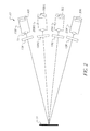
- RGBC data One method of providing RGBC data is shown in the embodiment of Figure 2.
- Four cameras 20R, 20G, 20BG, and 20B are aligned to a scene 14, each camera having a separate color filter 10R, 10G, 10BG, 10B respectively, positioned in front of it.
- a lens 15 images scene 14 onto an appropriate area array photosensor 30R, 30G, 30BG, 30B.
- the advantage of this arrangement is high resolution imaging in each color, R, G, B, C.
- a difficulty with this arrangement, in addition to cost, is the task of keeping all four cameras registered.
- FIG. 3 A second embodiment is shown in Figure 3, wherein a single camera 20 with a single area array photosensor 30 is used with a color filter wheel 25 containing red 10R, green 10G, blue-green 10BG, and blue 10B filters positioned in front of the camera and a color sequential signal produced.
- Color filter wheel 25 can be replaced by an electronically switchable LCD color filter such as devices made by ColorLink Inc., Boulder, Colorado. This type of color filter is typically operated between crossed polarizers (not shown).
- camera 20 comprises an image acquisition unit 120 that contains the optical and electronic components for focus, sensing, and initial light acquisition.
- a signal processing unit 126 accepts and processes the sensed data values from photosensor 30.
- signal processing unit 126 processes the sequential color data that is output from imaging acquisition unit 120.
- a control logic processor 122 typically a microprocessor or equivalent logic processing device, coordinates and controls the acquisition of image data and the interaction of image acquisition unit 120 and signal processing unit 126.
- An image data storage device 124 stores the final four-color data that is obtained for each image pixel.
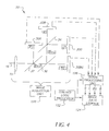
- a third embodiment is shown in Figure 4, wherein camera 20 has four area array photosensors 30, and white light 16 from a scene is spectrally divided for the four sensors 30R, 30G, 30BG, 30B, one each for red, green, blue-green, and blue.
- White light 16 passes through lens 15, and is divided by a dichroic mirror 32 into red light and blue-green light.
- the red light in this case, reflects from dichroic mirror 32 and impinges onto CCD array 30R.
- the blue, green, and blue-green light is transmitted to a beamsplitter 36, which could be a pellicle or partially silvered mirror, for example. Beamsplitter 36 does not have to divide the light equally.
- each photosensor 30 can be separately tuned to a suitable sensitivity value for the level of incident light.
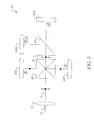
- a fourth embodiment is shown in Figure 5, wherein an X-cube 38 is used to separate the s-polarized red and blue colors (denoted by the dots) from the incoming light from lens 15.
- a filter 32 reflects red, blocking red light that may leak through X-cube 38 and passes blue and green.
- a dichroic mirror 34 is used to complete and clean up the color separation.
- the x-cube passes green of both polarizations (as shown by the dot and the arrow) and will also pass s-polarized (arrow) blue and red light.
- Dichroic filter 34 is designed to reflect the remainder of the blue and the shorter wavelengths of the green light to blue-green sensor 30BG. The balance of the green light is transmitted to green sensor 30G.
- Figure 6 shows a preferred arrangement of RGBC filters in a color filter array.
- fourth color C is cyan, the blue-green filter that can have a narrower bandwidth than the full blue and green spectra, which ranges from the 400 to 600nm normally be associated with cyan.
- a suitable cyan filter may have a passband of 470 to 530 nm.
- the green and blue-green filters can be used to represent the luminance signal, and are alternated with red and blue. In this way, the "luminance" signal will have higher resolution than the red and blue "chrominance” signals.
- the filters are arranged in a manner similar to that shown in U.S. Patent Nos. 5,631,703 and 6,330,029 so that interpolation is improved and that good resolution is maintained in the diagonal direction, as well as vertical and horizontal directions.
- Such a sensor can be incorporated in a camera similar to that illustrated in Figure 9.
- Figure 7a shows image acquisition unit 120 in camera 20 which uses two area array photosensors 40, 42, each with a separate color filter array.
- array photosensor 42 has a combination of G and C filters and can be used directly as the luminance signal because the eye is most sensitive to these wavelengths.
- the other sensor, array photosensor 40 has R and B filters.
- the light entering the camera passes through lens 15 and is imaged on one of the two array photosensors 40, 42. Some of the light is transmitted by beamsplitter 36 and is imaged onto the array photo 42 sensor having a green and blue-green color filter array. The remainder of the light is reflected to array photosensor 40 having a red and blue color filter array.
- Beamsplitter 36 can be a mirror, pellicle, or a dichroic mirror. A dichroic device may be more expensive but has the advantage of light efficiency and possibly improved contrast. Beamsplitter need not be 50-50 with reflect to reflected versus transmitted light. More light could be directed to one detector or the other to compensate for
- a hybrid design for camera 20 with two area array photosensors as shown in Figure 7a is a compromise between the four sensor camera of Figures 4 and 5 which is harder to align but needs no interpolation and a single sensor camera as in Figure 3 which is much easier to align but is neither as accurate in color rendition nor as high in resolution.
- the two array camera can be more compact and less expensive than the four color device and does not require expensive prisms or dichroic components.
- Figure 8a shows a preferred arrangement of G and B-G filters in a CFA for use in a camera illustrated in Figure 7a.
- Figure 8b shows a preferred arrangement of R and B filters in a CFA for use in a camera illustrated in Figure 7a.
- Figure 7b shows image acquisition unit 120 having R and G filters on area array photosensor 46 and C and B filters on area array photosensor 48, grouping the filters by closest wavelength.
- This arrangement may be the most advantageous with respect to dichroic beamsplitter 36 design, since all wavelengths above a threshold are reflected, and all wavelengths below the threshold are transmitted.
- the arrangement of Figure 7a transmitted wavelengths toward the middle of the visible spectrum, reflecting higher and lower wavelengths.
- Figure 7a would thus be optimal for an imaging system such as NTSC using luminance information.
- the colors reflected and the colors transmitted shown in Figures 7a and 7b could be reversed. Not all imaging systems require a TV style signal based on luminance and chrominance. Where broadcast bandwidth is not an issue, as with digital cinema projectors and color printers, the R, G, C, B signals can be used directly.
- the filter arrays needed for the camera illustrated in Figure 7b are constructed as shown in Figures 8c and 8d.
- FIG 9 shows an alternate embodiment of camera 20 where imaging lens 15 images light from scene 14 (not shown in Figure 9) onto a multicolor color filter array photosensor 60.
- Photosensor 60 might use an array configured as that shown in Figure 6 as an RGBC CFA. It could have any of a number of other configurations including a CMY array.
- the red, green and blue signals can be derived algebraically from the CMY signals and the blue-green signal can use a scaled version of the cyan signal.
- the Moorman filter is arranged as follows:
- G filters can be replaced with a C filter which represents blue-green, for example:
Landscapes
- Engineering & Computer Science (AREA)
- Multimedia (AREA)
- Signal Processing (AREA)
- Physics & Mathematics (AREA)
- Spectroscopy & Molecular Physics (AREA)
- Color Television Image Signal Generators (AREA)
- Image Input (AREA)
- Facsimile Heads (AREA)
Abstract
Description
- CRGG
- GCGB
- GGCR
- BGGC
Claims (9)
- A color imaging device comprising an array of light sensitive elements:a first type of element sensitive to a blue spectral region;a second type of element sensitive to a red spectral region;a third type of element sensitive to a green spectral region; anda fourth type of element sensitive to a blue-green portion of said spectral region.
- A color imaging device as in claim 1 wherein said light sensitive elements are comprised of a photosensor and a transmissive color filter.
- A color image sensor comprising:wherein such filter elements are arranged in repeating patterns in two perpendicular directions throughout substantially the entire imaging area of the sensor.a substantially planar array of solid state light sensitive elements; anda filter mosaic made up of individual filter elements which are superposed in one-to-one registry on said light sensitive elements, such mosaic being comprised of:a first type of filter element transparent to green;a second type of filter element transparent to red;a third type of filter element transparent to blue;a fourth type of filter element transparent to blue-green; and
- A color imaging device as in claim 3 wherein said pattern is:R G B B-GG R B-G BB B-G R GB-G B G R
- A color imaging device comprising:a first digital camera comprising a first sensor array and a first color filter for filtering all light except light associated with a first spectral region;a second digital camera comprising a second sensor array and a second color filter excluding all light except that associated with a second spectral region;a third digital camera comprising a third sensor array and a third color filter for filtering all light except light associated with a third spectral region; anda fourth digital camera comprising a fourth sensor array and a fourth color filter for filtering all light except light associated with a fourth spectral region.
- A digital camera comprising:a sensor array;a color filter wheel; andwherein said color filter wheel selectively transmits light associated with four spectral regions.
- A digital camera comprising:a sensor array; andan electronically switchable filter capable of selectively transmitting light from four spectral regions.
- A digital camera comprising:at least one dichroic beamsplitter;a first sensor array which receives light from said dichroic beamsplitter in a first spectral region;a second sensor array which receives light from said dichroic beamsplitter in a second spectral region;a third sensor array which receives light from said dichroic beamsplitter in a third spectral region; anda fourth sensor array which receives light from said dichroic beamsplitter in a fourth spectral region.
- A digital camera as in claim 8 wherein one of said dichroic beamsplitters is an X-cube beamsplitter.
Applications Claiming Priority (2)
| Application Number | Priority Date | Filing Date | Title |
|---|---|---|---|
| US82936 | 2002-02-26 | ||
| US10/082,936 US7057654B2 (en) | 2002-02-26 | 2002-02-26 | Four color image sensing apparatus |
Publications (2)
| Publication Number | Publication Date |
|---|---|
| EP1339238A2 true EP1339238A2 (en) | 2003-08-27 |
| EP1339238A3 EP1339238A3 (en) | 2005-01-26 |
Family
ID=27660370
Family Applications (1)
| Application Number | Title | Priority Date | Filing Date |
|---|---|---|---|
| EP03075426A Withdrawn EP1339238A3 (en) | 2002-02-26 | 2003-02-14 | Four color image sensing apparatus |
Country Status (4)
| Country | Link |
|---|---|
| US (1) | US7057654B2 (en) |
| EP (1) | EP1339238A3 (en) |
| JP (1) | JP2003274424A (en) |
| CN (1) | CN1441603A (en) |
Cited By (5)
| Publication number | Priority date | Publication date | Assignee | Title |
|---|---|---|---|---|
| EP1686535A1 (en) * | 2005-01-26 | 2006-08-02 | Mitutoyo Corporation | Image measuring apparatus and image measuring method |
| WO2006080220A1 (en) | 2005-01-31 | 2006-08-03 | Sony Corporation | Imaging device and imaging element |
| WO2013036648A1 (en) * | 2011-09-09 | 2013-03-14 | Apple Inc. | Digital camera with light splitter |
| EP3462724A1 (en) * | 2017-09-29 | 2019-04-03 | Thomson Licensing | Reduced optical crosstalk plenoptic imaging device, corresponding method, computer program product, computer-readable carrier medium and apparatus |
| EP4213479A4 (en) * | 2020-09-16 | 2024-02-21 | Guangdong Oppo Mobile Telecommunications Corp., Ltd. | IMAGE SENSOR, TERMINAL, DATA PROCESSING METHOD AND DEVICE AND STORAGE MEDIUM |
Families Citing this family (56)
| Publication number | Priority date | Publication date | Assignee | Title |
|---|---|---|---|---|
| US20050151860A1 (en) * | 2004-01-08 | 2005-07-14 | Silverstein D. A. | Image sensing device and method |
| JP4396332B2 (en) * | 2004-03-10 | 2010-01-13 | セイコーエプソン株式会社 | Digital camera |
| US20050219659A1 (en) * | 2004-03-31 | 2005-10-06 | Shuxue Quan | Reproduction of alternative forms of light from an object using digital imaging system |
| US7583303B2 (en) * | 2005-01-31 | 2009-09-01 | Sony Corporation | Imaging device element |
| US7568628B2 (en) | 2005-03-11 | 2009-08-04 | Hand Held Products, Inc. | Bar code reading device with global electronic shutter control |
| US7780089B2 (en) | 2005-06-03 | 2010-08-24 | Hand Held Products, Inc. | Digital picture taking optical reader having hybrid monochrome and color image sensor array |
| US7611060B2 (en) | 2005-03-11 | 2009-11-03 | Hand Held Products, Inc. | System and method to automatically focus an image reader |
| DE602006012954D1 (en) * | 2005-04-15 | 2010-04-29 | Koninkl Philips Electronics Nv | COLOR DISPLAY DEVICE AND OPERATING METHOD THEREFOR |
| US7770799B2 (en) | 2005-06-03 | 2010-08-10 | Hand Held Products, Inc. | Optical reader having reduced specular reflection read failures |
| JP2007006061A (en) * | 2005-06-23 | 2007-01-11 | Canon Inc | Color filter and imaging apparatus having the same |
| US8760485B2 (en) * | 2006-03-02 | 2014-06-24 | Cisco Technology, Inc. | System and method for displaying participants in a videoconference between locations |
| JP4836625B2 (en) * | 2006-03-24 | 2011-12-14 | パナソニック株式会社 | Solid-state image sensor |
| WO2008075266A2 (en) * | 2006-12-19 | 2008-06-26 | Philips Intellectual Property & Standards Gmbh | Colour sequential flash for digital image acquisition |
| US20090201487A1 (en) * | 2007-08-17 | 2009-08-13 | Princeton Satellite Systems, Inc. | Multi spectral vision system |
| US8452082B2 (en) * | 2007-09-27 | 2013-05-28 | Eastman Kodak Company | Pattern conversion for interpolation |
| US20090159799A1 (en) * | 2007-12-19 | 2009-06-25 | Spectral Instruments, Inc. | Color infrared light sensor, camera, and method for capturing images |
| US20110013056A1 (en) * | 2009-07-17 | 2011-01-20 | Searete Llc, A Limited Liability Corporation Of The State Of Delaware | Color filters and demosaicing techniques for digital imaging |
| TWI493277B (en) * | 2011-03-18 | 2015-07-21 | Hon Hai Prec Ind Co Ltd | Stereograph capturing device |
| JP5923754B2 (en) * | 2011-08-11 | 2016-05-25 | パナソニックIpマネジメント株式会社 | 3D imaging device |
| US20140063300A1 (en) * | 2012-09-06 | 2014-03-06 | Aptina Imaging Corporation | High dynamic range imaging systems having clear filter pixel arrays |
| DE102013000301A1 (en) | 2013-01-10 | 2014-07-10 | Basler Ag | Method and device for producing an improved color image with a color filter sensor |
| WO2014153057A1 (en) | 2013-03-14 | 2014-09-25 | James Olson | Improved multi-channel camera system |
| US9332235B2 (en) | 2013-12-10 | 2016-05-03 | Visera Technologies Company Limited | Imaging capture apparatus having plurality of image sensors generating respective image signals based on emitted light areas |
| US20160255323A1 (en) | 2015-02-26 | 2016-09-01 | Dual Aperture International Co. Ltd. | Multi-Aperture Depth Map Using Blur Kernels and Down-Sampling |
| US10313642B2 (en) * | 2017-01-18 | 2019-06-04 | Omnivision Technologies, Inc. | Imaging system having dual image sensors |
| US10431616B2 (en) | 2017-12-20 | 2019-10-01 | Google Llc | Color filter arrays for image sensors |
| RU2711121C1 (en) * | 2018-08-14 | 2020-01-15 | Александр Георгиевич Носков | Complex of four-color digital television full colours |
| US11587491B1 (en) | 2018-10-25 | 2023-02-21 | Baylor University | System and method for a multi-primary wide gamut color system |
| US12444337B2 (en) | 2018-10-25 | 2025-10-14 | Baylor University | System and method for a multi-primary wide gamut color system |
| US10997896B2 (en) * | 2018-10-25 | 2021-05-04 | Baylor University | System and method for a six-primary wide gamut color system |
| US11030934B2 (en) | 2018-10-25 | 2021-06-08 | Baylor University | System and method for a multi-primary wide gamut color system |
| US10607527B1 (en) | 2018-10-25 | 2020-03-31 | Baylor University | System and method for a six-primary wide gamut color system |
| US11410593B2 (en) | 2018-10-25 | 2022-08-09 | Baylor University | System and method for a multi-primary wide gamut color system |
| US11043157B2 (en) | 2018-10-25 | 2021-06-22 | Baylor University | System and method for a six-primary wide gamut color system |
| US12475826B2 (en) | 2018-10-25 | 2025-11-18 | Baylor University | System and method for a multi-primary wide gamut color system |
| US12555507B2 (en) | 2018-10-25 | 2026-02-17 | Baylor University | System and method for a multi-primary wide gamut color system |
| US11189210B2 (en) | 2018-10-25 | 2021-11-30 | Baylor University | System and method for a multi-primary wide gamut color system |
| US11289000B2 (en) | 2018-10-25 | 2022-03-29 | Baylor University | System and method for a multi-primary wide gamut color system |
| US11403987B2 (en) | 2018-10-25 | 2022-08-02 | Baylor University | System and method for a multi-primary wide gamut color system |
| US11069280B2 (en) | 2018-10-25 | 2021-07-20 | Baylor University | System and method for a multi-primary wide gamut color system |
| US11289003B2 (en) | 2018-10-25 | 2022-03-29 | Baylor University | System and method for a multi-primary wide gamut color system |
| US11037481B1 (en) | 2018-10-25 | 2021-06-15 | Baylor University | System and method for a multi-primary wide gamut color system |
| US11475819B2 (en) | 2018-10-25 | 2022-10-18 | Baylor University | System and method for a multi-primary wide gamut color system |
| US11532261B1 (en) | 2018-10-25 | 2022-12-20 | Baylor University | System and method for a multi-primary wide gamut color system |
| US11488510B2 (en) | 2018-10-25 | 2022-11-01 | Baylor University | System and method for a multi-primary wide gamut color system |
| US12444334B2 (en) | 2018-10-25 | 2025-10-14 | Baylor University | System and method for a multi-primary wide gamut color system |
| WO2020244765A1 (en) * | 2019-06-06 | 2020-12-10 | Huawei Technologies Co., Ltd. | Color filter array apparatus |
| WO2021041841A1 (en) | 2019-08-30 | 2021-03-04 | Flir Commercial Systems, Inc. | Multispectral imaging for navigation systems and methods |
| EP4124031A4 (en) * | 2020-03-16 | 2023-11-22 | Sony Semiconductor Solutions Corporation | IMAGING ELEMENT AND ELECTRONIC INSTRUMENT |
| CN111586277B (en) * | 2020-06-17 | 2025-09-19 | 中国科学技术大学 | Light splitting stereoscopic vision device for detecting inside cavity of high Wen Xiazhai |
| CN111818314A (en) * | 2020-06-23 | 2020-10-23 | 北京迈格威科技有限公司 | A filter array and image sensor |
| CN112019822B (en) * | 2020-08-05 | 2025-02-14 | 北京爱芯科技有限公司 | A filter array and an image sensor |
| CN111918004B (en) * | 2020-09-16 | 2023-07-04 | Oppo广东移动通信有限公司 | Image sensor, terminal, data processing method, device and storage medium |
| US12198294B2 (en) * | 2022-02-02 | 2025-01-14 | Xlnx, Inc. | Neural network processing of reordered color filter array formatted image data |
| WO2024118888A1 (en) * | 2022-11-30 | 2024-06-06 | The Trustees Of Columbia University In The City Of New York | Four-way image splitter for high-speed characterization of tissue samples |
| US12462772B1 (en) | 2024-06-20 | 2025-11-04 | 6P Color, Inc. | System and method for conversion from XYZ to multiple primaries using pseudo white points |
Family Cites Families (27)
| Publication number | Priority date | Publication date | Assignee | Title |
|---|---|---|---|---|
| US3971065A (en) | 1975-03-05 | 1976-07-20 | Eastman Kodak Company | Color imaging array |
| JPS54158818A (en) * | 1978-06-05 | 1979-12-15 | Nec Corp | Color solid-state pickup unit |
| US4286285A (en) * | 1980-02-04 | 1981-08-25 | Rca Corporation | Checkerboard color filter providing tolerance |
| US4404585A (en) * | 1981-10-08 | 1983-09-13 | Hjortzberg Bernhard A | Video sequential color system |
| JP2872759B2 (en) | 1989-06-08 | 1999-03-24 | 富士写真フイルム株式会社 | Solid-state imaging system |
| US5251019A (en) | 1991-01-25 | 1993-10-05 | Eastman Kodak Company | Solid state color image sensor using a field-staggered color filter pattern |
| JP2936760B2 (en) | 1991-02-25 | 1999-08-23 | ソニー株式会社 | Color television camera device |
| JPH05219513A (en) | 1992-01-27 | 1993-08-27 | Ikegami Tsushinki Co Ltd | Solid-state image pickup device |
| JP3392886B2 (en) * | 1992-06-18 | 2003-03-31 | ペンタックス株式会社 | Still video camera |
| US5382976A (en) * | 1993-06-30 | 1995-01-17 | Eastman Kodak Company | Apparatus and method for adaptively interpolating a full color image utilizing luminance gradients |
| JPH0879770A (en) | 1994-08-31 | 1996-03-22 | Mitsubishi Electric Corp | Imaging device |
| KR0169376B1 (en) * | 1995-10-10 | 1999-03-20 | 김광호 | Multi-media ccd camera system |
| US5708264A (en) | 1995-11-07 | 1998-01-13 | Eastman Kodak Company | Planar color filter array for CCDs from dyed and mordant layers |
| US5677202A (en) | 1995-11-20 | 1997-10-14 | Eastman Kodak Company | Method for making planar color filter array for image sensors with embedded color filter arrays |
| US5917560A (en) * | 1995-11-28 | 1999-06-29 | Raytheon Company | Low cost color cube for liquid crystal light valve projector |
| US5796433A (en) * | 1996-03-20 | 1998-08-18 | Loral Fairchild Corp. | Multiple-frame CCD image sensor with overlying photosensitive layer |
| DE19616440A1 (en) | 1996-04-25 | 1997-10-30 | Eastman Kodak Co | Method and device for obtaining a full color image or multispectral image from image data of a CCD image sensor with a mosaic color filter |
| US5631703A (en) | 1996-05-29 | 1997-05-20 | Eastman Kodak Company | Particular pattern of pixels for a color filter array which is used to derive luminance and chrominance values |
| US5798542A (en) | 1996-10-08 | 1998-08-25 | Eastman Kodak Company | Image sensor having ITO electrodes with overlapping color filters for increased sensitivity |
| JPH10148885A (en) | 1996-11-19 | 1998-06-02 | Sony Corp | Projector device |
| US6181376B1 (en) | 1997-10-14 | 2001-01-30 | Intel Corporation | Method of determining missing color values for pixels in a color filter array |
| US6256073B1 (en) | 1997-11-26 | 2001-07-03 | Texas Instruments Incorporated | Color source selection for improved brightness |
| US5990950A (en) | 1998-02-11 | 1999-11-23 | Iterated Systems, Inc. | Method and system for color filter array multifactor interpolation |
| US6330029B1 (en) | 1998-03-17 | 2001-12-11 | Eastman Kodak Company | Particular pattern of pixels for a color filter array which is used to derive luminance and chrominance values |
| US6611289B1 (en) * | 1999-01-15 | 2003-08-26 | Yanbin Yu | Digital cameras using multiple sensors with multiple lenses |
| US6220710B1 (en) | 1999-05-18 | 2001-04-24 | Intel Corporation | Electro-optic projection display with luminosity channel |
| US6870523B1 (en) | 2000-06-07 | 2005-03-22 | Genoa Color Technologies | Device, system and method for electronic true color display |
-
2002
- 2002-02-26 US US10/082,936 patent/US7057654B2/en not_active Expired - Lifetime
-
2003
- 2003-02-14 EP EP03075426A patent/EP1339238A3/en not_active Withdrawn
- 2003-02-25 JP JP2003047811A patent/JP2003274424A/en active Pending
- 2003-02-26 CN CN03106616A patent/CN1441603A/en active Pending
Cited By (12)
| Publication number | Priority date | Publication date | Assignee | Title |
|---|---|---|---|---|
| EP1686535A1 (en) * | 2005-01-26 | 2006-08-02 | Mitutoyo Corporation | Image measuring apparatus and image measuring method |
| US7613359B2 (en) | 2005-01-26 | 2009-11-03 | Mitutoyo Corporation | Single-chip color camera for high accuracy image measurements |
| WO2006080220A1 (en) | 2005-01-31 | 2006-08-03 | Sony Corporation | Imaging device and imaging element |
| EP1729524A4 (en) * | 2005-01-31 | 2012-01-04 | Sony Corp | ELEMENT AND DEVICE FOR SHOOTING |
| WO2013036648A1 (en) * | 2011-09-09 | 2013-03-14 | Apple Inc. | Digital camera with light splitter |
| US20130063629A1 (en) * | 2011-09-09 | 2013-03-14 | Apple Inc. | Digital camera with light splitter |
| US8988564B2 (en) | 2011-09-09 | 2015-03-24 | Apple Inc. | Digital camera with light splitter |
| US20150177524A1 (en) * | 2011-09-09 | 2015-06-25 | Apple Inc. | Digital camera with light splitter |
| US9465221B2 (en) | 2011-09-09 | 2016-10-11 | Apple Inc. | Digital camera with light splitter |
| EP3462724A1 (en) * | 2017-09-29 | 2019-04-03 | Thomson Licensing | Reduced optical crosstalk plenoptic imaging device, corresponding method, computer program product, computer-readable carrier medium and apparatus |
| WO2019063768A1 (en) * | 2017-09-29 | 2019-04-04 | Thomson Licensing | Reduced optical crosstalk plenoptic imaging device, corresponding method, computer program product, computer-readable carrier medium and apparatus |
| EP4213479A4 (en) * | 2020-09-16 | 2024-02-21 | Guangdong Oppo Mobile Telecommunications Corp., Ltd. | IMAGE SENSOR, TERMINAL, DATA PROCESSING METHOD AND DEVICE AND STORAGE MEDIUM |
Also Published As
| Publication number | Publication date |
|---|---|
| US7057654B2 (en) | 2006-06-06 |
| JP2003274424A (en) | 2003-09-26 |
| US20030160881A1 (en) | 2003-08-28 |
| EP1339238A3 (en) | 2005-01-26 |
| CN1441603A (en) | 2003-09-10 |
Similar Documents
| Publication | Publication Date | Title |
|---|---|---|
| US7057654B2 (en) | Four color image sensing apparatus | |
| Lyon et al. | Eyeing the camera: Into the next century | |
| US11553165B2 (en) | Color night vision cameras, systems, and methods thereof | |
| US7400332B2 (en) | Hexagonal color pixel structure with white pixels | |
| CN1177467C (en) | Color imaging system with infrared correction function and its imaging method | |
| CN102959958B (en) | color imaging device | |
| EP1686810A1 (en) | Multi-spectrum image pick up device | |
| EP1594321A2 (en) | Extended dynamic range in color imagers | |
| US6803955B1 (en) | Imaging device and imaging apparatus | |
| CN101188775A (en) | Color imaging element and color signal processing circuit | |
| JP2004228662A (en) | Imaging device | |
| US20030151685A1 (en) | Digital video camera having only two CCDs | |
| US9143747B2 (en) | Color imaging element and imaging device | |
| JP3784602B2 (en) | Image reading method and image reading system | |
| US6650795B1 (en) | Color image capturing system with antialiazing | |
| US20020101525A1 (en) | Image interpolating device | |
| EP0428884A1 (en) | Colour filter arrangement for a solid-state imaging apparatus | |
| EP1395062A1 (en) | Color image pickup device | |
| JP4441809B2 (en) | Color solid-state imaging device | |
| JP2677550B2 (en) | Solid-state imaging device | |
| US6768510B2 (en) | Color correction for RGB | |
| JPS5911308B2 (en) | Color Kotai Satsuzou Sochi | |
| JPH10243409A (en) | Two-chip imaging device | |
| JP3515585B2 (en) | Two-chip imaging device | |
| JPH0139273B2 (en) |
Legal Events
| Date | Code | Title | Description |
|---|---|---|---|
| PUAI | Public reference made under article 153(3) epc to a published international application that has entered the european phase |
Free format text: ORIGINAL CODE: 0009012 |
|
| AK | Designated contracting states |
Designated state(s): AT BE BG CH CY CZ DE DK EE ES FI FR GB GR HU IE IT LI LU MC NL PT SE SI SK TR |
|
| AX | Request for extension of the european patent |
Extension state: AL LT LV MK RO |
|
| PUAL | Search report despatched |
Free format text: ORIGINAL CODE: 0009013 |
|
| AK | Designated contracting states |
Kind code of ref document: A3 Designated state(s): AT BE BG CH CY CZ DE DK EE ES FI FR GB GR HU IE IT LI LU MC NL PT SE SI SK TR |
|
| AX | Request for extension of the european patent |
Extension state: AL LT LV MK RO |
|
| 17P | Request for examination filed |
Effective date: 20050613 |
|
| AKX | Designation fees paid |
Designated state(s): DE |
|
| STAA | Information on the status of an ep patent application or granted ep patent |
Free format text: STATUS: THE APPLICATION HAS BEEN WITHDRAWN |
|
| 18W | Application withdrawn |
Effective date: 20051125 |