EP1339196A1 - System and method for feedforward data-aided channel estimation - Google Patents
System and method for feedforward data-aided channel estimation Download PDFInfo
- Publication number
- EP1339196A1 EP1339196A1 EP20030003171 EP03003171A EP1339196A1 EP 1339196 A1 EP1339196 A1 EP 1339196A1 EP 20030003171 EP20030003171 EP 20030003171 EP 03003171 A EP03003171 A EP 03003171A EP 1339196 A1 EP1339196 A1 EP 1339196A1
- Authority
- EP
- European Patent Office
- Prior art keywords
- channel estimate
- block
- slot
- channel
- blocks
- Prior art date
- Legal status (The legal status is an assumption and is not a legal conclusion. Google has not performed a legal analysis and makes no representation as to the accuracy of the status listed.)
- Granted
Links
Images






Classifications
-
- H—ELECTRICITY
- H04—ELECTRIC COMMUNICATION TECHNIQUE
- H04L—TRANSMISSION OF DIGITAL INFORMATION, e.g. TELEGRAPHIC COMMUNICATION
- H04L25/00—Baseband systems
- H04L25/02—Details ; arrangements for supplying electrical power along data transmission lines
- H04L25/0202—Channel estimation
- H04L25/0224—Channel estimation using sounding signals
- H04L25/0228—Channel estimation using sounding signals with direct estimation from sounding signals
- H04L25/023—Channel estimation using sounding signals with direct estimation from sounding signals with extension to other symbols
- H04L25/0232—Channel estimation using sounding signals with direct estimation from sounding signals with extension to other symbols by interpolation between sounding signals
Definitions
- the invention relates to system and method of interference suppression, more specifically to system and method of interference suppression for suppressing interference signal in mobile communication.
- an interference suppression receiving method for suppressing interference caused by a delayed wave or a multi-user is implemented for increasing capacity for subscribers.
- a receiver calculates a channel estimate vector by using a known series symbol within a received slot for estimating variations in phase and amplitude of a received signal resulting from arrival timing for each chip level in each received slot or fading fluctuation of each propagation channel, and performs a channel equalizing calculation by using the channel estimate vector to suppress interference caused by a delayed wave or a multi-user within the slot.
- An interference suppression receiving system shown in FIG. 14 is a system whose input is a received signal including a known series symbol part for estimating a propagation channel and a data part and that outputs a demodulated signal by performing demodulation.
- a data part of a received signal is divided into several blocks at block dividing process 11 and passed to suppression process 15 for suppressing an interference signal.
- a channel estimate vector is calculated by using a known series symbol part of a received signal and passed to the suppression process 15.
- a conventional interference suppression receiving system uses a channel estimate vector calculated by using a known series symbol part, which is a part of a slot, as a channel estimate vector for the entire slot.
- this conventional system has a problem that an actual channel estimate vector for a data part becomes different from a channel estimate vector for a known series symbol because of fading.
- the present invention intends to provide a system and method of interference suppression that can perform an interference suppression on a received signal in more precise way than in conventional arts.
- the invention thus concerns an interference suppression system for suppressing an interference signal for a received signal including a plurality of slots having a known series symbol part for estimating a propagation channel and a data part, including: block dividing means for dividing the above-mentioned data part of a received signal into a plurality of blocks; channel estimate calculation means for calculating a channel estimate for the current slot by using the above-mentioned known series symbol part of a received signal; channel estimate storage means for storing the channel estimate for the slot calculated at the above-mentioned channel estimate calculation means; channel estimate calculation means for each block for calculating a channel estimate for each block for each of the above-mentioned plurality of blocks by using a channel estimate for the current slot calculated at the above-mentioned channel estimate calculation means and a channel estimate stored in the above-mentioned channel estimate storage means; and suppression means for suppressing the above-mentioned interference signal by performing a calculation for each of the above-mentioned blocks by using the above-mentioned channel estimate
- a calculation performed at the above-mentioned suppression means may be single user detection or joint detection.
- the calculation performed at the above-mentioned suppression means may be RAKE combiner.
- the above-mentioned channel estimate calculation means for each block advantageously previously calculates a channel estimate for the next slot and then calculates the above-mentioned channel estimate for each block for the above-mentioned current slot by using the calculated channel estimate for the next channel and a channel estimate for the above-mentioned current slot when the above-mentioned channel estimate storage means stores no channel estimate.
- the above-mentioned block dividing means may divide a data part of the above-mentioned received signal into as many blocks as the number corresponding to magnitude of a difference between a channel estimate for the current slot calculated at the above-mentioned channel estimate calculation means and a channel estimate stored in the above-mentioned channel estimate storage means.
- the above-mentioned block dividing means may divide the above-mentioned data part of a received signal into as many blocks as the number corresponding to magnitude of a fading frequency of a propagation channel.
- the above-mentioned block dividing means may divide the above-mentioned data part of a received signal into as many blocks as the number corresponding to a type of data modulation being used.
- the above-mentioned block dividing means may divide the above-mentioned data part of a received signal into as many blocks as the number corresponding to modulation and a coding rate being adaptively used.
- an interference suppression method for suppressing interference signal for a received signal including a plurality of slots having a known series symbol part for estimating a propagation channel and a data part includes a block dividing step for dividing the above-mentioned data part of a received signal into a plurality of blocks, a channel estimate calculation step for calculating a channel estimate for the current slot by using the above-mentioned known series symbol part of a received signal, a channel estimate calculation step for each block for calculating a channel estimate for each block for each of the above-mentioned plurality of blocks by using a channel estimate for the current slot calculated at the above-mentioned channel estimate calculation step and a channel estimate for a previous slot, and a suppression step for suppressing the above-mentioned interference signal by performing a calculation for the above-mentioned each block by using the above-mentioned channel estimate for each block.
- a calculation performed at the above-mentioned suppression step may be single user detection or joint detection.
- the calculation performed at the above-mentioned suppression step may be RAKE combiner.
- the above-mentioned channel estimate calculation step for each block further may include a step for previously calculating a channel estimate for the next slot when no channel estimate for previous slots exists, and wherein, when the channel estimate for the next slot is obtained, a channel estimate for each block for the above-mentioned current slot is calculated by using the channel estimate for the next slot and a channel estimate for the above-mentioned current slot.
- a data part of the above-mentioned received signal may be divided into as many blocks as the number corresponding to magnitude of a difference between a channel estimate for the current slot calculated at the above-mentioned channel estimate calculation step and a channel estimate for a previous slot.
- the above-mentioned data part of a received signal may be divided into as many blocks as the number corresponding to magnitude of a fading frequency of a propagation channel.
- a data part of the above-mentioned received signal may be divided into as many blocks as the number corresponding to a type of data modulation being used.
- the above-mentioned data part of a received signal may be divided into as many blocks as the number corresponding to modulation and a coding rate being adaptively used.
- the present invention can perform more precise interference suppression for a received signal than conventional arts by dividing a data part of a received slot into several blocks, calculating a channel estimate vector for each block on the basis of a channel estimate vector of previous slot and a channel estimate vector for the slot, and performing a calculation including a channel equalizing calculation for each block.
- FIG. 1 is a block diagram illustrating an embodiment of the interference suppression system.
- FIG. 2 is a block diagram showing a configuration of a first example of an interference suppression system.
- FIG. 3 is a diagram illustrating an arrangement of slots in the interference suppression system shown in FIG. 2.
- FIG. 4 is a diagram illustrating an arrangement of slots in CDMA/TDD system.
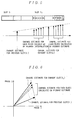
- FIG. 5 is a conceptual diagram for calculating a channel estimate for each block by primary interpolation of a channel estimate for the previous slot and a channel estimate for the current slot.
- FIG. 6 is a conceptual diagram for calculating a channel estimate for each block by primary interpolation of a channel estimate for the previous slot and a channel estimate for the current slot in phase I and phase Q.
- FIG. 7 is a flow chart showing a calculation of a third example of the interference suppression system.
- FIG. 8 is a flow chart showing a calculation of a forth example of the interference suppression system.
- FIG. 9 is a flow chart showing a calculation of a fifth example of the interference suppression system.
- FIG. 10 is a flow chart showing a calculation of a sixth example of the interference suppression system.
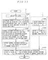
- FIG. 11 is a flow chart showing a calculation of a seventh example of the interference suppression system.
- FIG. 12 is a block diagram showing a configuration of an eighth example of the interference suppression system.
- FIG. 13 is a block diagram showing a configuration of a ninth example of the interference suppression system.
- FIG. 14 is a block diagram showing a configuration of the conventional interference suppression system.
- the interference suppression system shown in Fig. 1 is a system the input of which is a received signal including a known series symbol part for estimating a propagation channel and a data part and that outputs a demodulated signal by performing demodulation for each slot.
- a data part of a received signal is divided into several blocks at block dividing process 11 and then passed to suppression process 15 for suppressing interference signal.
- a channel estimate vector is calculated by using a known series symbol part of a received signal.
- the calculated channel estimate vector is stored at channel estimate storage process 14.
- a channel estimate for each block is calculated for each of the blocks by using the current channel estimate vector calculated at channel estimate calculation process 12 and the previous channel estimate vector stored at channel estimate storage process 14.
- the calculated channel estimate for each block is passed to suppression process 15 where interference signal is suppressed.
- the system includes block dividing section 1 for dividing a data part of a received signal into a plurality of blocks, channel estimator 2 whose input is a known series symbol part of a received signal, channel estimate storage device 4 for storing a channel estimate vector calculated at channel estimator 2, channel estimate calculator for each block 3 whose input is a channel estimate vector calculated at channel estimator 2 and contents of channel estimate storage device 4, channel equalizer 5 whose input is an output from block dividing section 1 and an output from channel estimate calculator for each block 3 and that performs a channel equalizing calculation, and de-spreader 6 for performing de-spreading for an output from the channel equalizer 5 as shown in FIG. 2.
- the block dividing section 1 divides a data part of a received signal into a plurality of blocks and outputs each of the divided blocks to channel equalizer.
- the channel estimator 2 calculates a channel estimate vector H for estimating a propagation channel by using a known series symbol section, and outputs the channel estimate vector H for the current slot to channel estimate calculator for each block 3 and channel estimate storage device 4.
- the channel estimate storage device 4 stores a channel estimate vector H calculated at channel estimator 2. Therefore, the channel estimate storage device 4 outputs a "channel estimate vector H' for a previous slot" to channel estimate calculator for each block 3 as it demodulates following slots.
- the channel estimate calculator for each block 3 has a function that makes two types of operations available.
- One of the operations is outputting channel estimate vectors H B1 , H B2 , ..., H BK for respective blocks to channel equalizer 5 via a known primary interpolation on the basis of a channel estimate vector H input from channel estimator 2 and a channel estimate vector H' input from channel estimate storage device 4.
- Another operation is outputting a channel estimate vector H to channel equalizer 5 as channel estimate vectors H B1 , H B2 , ...H BK for respective blocks when neither a previous slot nor a channel estimate vector H' exists.
- the channel estimate calculator for each block 3 may be adapted to calculate a difference between a channel estimate vector H and a channel estimate vector H', and when the difference exceeds a specific threshold "g", perform the former of the above mentioned operations, and when the difference does not exceed a specific threshold, perform the latter of the above mentioned operations.
- the channel estimate calculator for each block 3 may also be adapted to stop demodulation of the current slot, calculate a channel estimate for the next slot and then calculates a channel estimate for each block for the current slot by using the channel estimate for the next slot and a channel estimate for the current slot when no channel estimate for a previous slot exists.
- the channel equalizer 5 performs a channel equalizing calculation for each block separately by using a channel estimate vector for each block obtained at channel estimate calculator for each block 3.
- the de-spreader 6 de-spreads a signal of a data part that has been subjected to a channel equalizing calculation at channel equalizer 5.
- a JD calculator may be used as in the eighth example as will be described below or a RAKE combiner may be used as in the ninth example described below instead of channel equalizer 5 and de-spreader 6.
- a JD calculator in this case is a calculator for performing joint-detection for each block separately by using an individual channel estimate vector for each block obtained at channel estimate calculator for each block 3.
- a RAKE combiner is a combiner for performing RAKE combination for each block separately by using an individual channel estimate vector for each block obtained at channel estimate calculator for each block 3.
- receiver 10 receives a series of N slots, i.e., slot S 1 , slot S 2 , ..., slot S N in the order of arrival as a received signal in burst mode.
- slot S 1 , slot S 2 , ..., slot S N have a data part, i.e., data D 1 , data D 2 , ..., data D N , and a known series symbol for estimating a propagation channel for each path, i.e., MA 1 , MA 2 , ..., MA N , respectively.
- Receiver 10 in FIG. 2 demodulates slot S 1 , slot S 2 , ..., slot S N in the order of arrival via demodulation described below.
- receiver 10 receives and demodulates a series of incoming slots one by one.
- Block dividing section 1 of receiver 10 divides n th slot S N in N slots into a data part (data D N ) and a known series symbol part (MA N ) on receiving the slot S N .
- Data D N is further divided into K blocks as shown in FIG. 3, i.e., block B 1 , block B 2 , ..., block B K . Each of these divided K blocks is output to channel equalizer 5.
- a symbol part MA N is input into channel estimator 2, where a channel estimate vector H for slot S K is calculated.
- the calculated channel estimate vector H is input and stored into channel estimate storage device 4, and also input into channel estimate calculator for each block 3.
- the channel estimate calculator for each block 3 calculates channel estimate vectors H B1 , H B2 , ..., H BK for respective blocks by performing primary interpolation on a vector H and a vector H' when a "channel estimate vector H' for a previous slot" exists.
- the channel estimate calculator for each block 3 outputs a channel estimate vector H for the current slot to channel equalizer 5 as channel estimate vectors H B1 , H B2 , ..., H BK for respective blocks.
- the channel equalizer 5 performs a channel equalizing calculation for respective blocks B 1 , B 2 , ..., B K by using channel estimate vectors H B1 , H B2 , ..., H BK for respective blocks. Then, de-spreader 6 performs de-spreading for demodulating the slot.
- the system can perform more precise interference suppression for a received signal than conventional arts by dividing a data part of a received slot into several blocks, calculating a channel estimate vector for each block by using a channel estimate vector for a previous slot and a channel estimate vector for the slot, and performing a channel equalizing calculation for each block for a received signal.
- FIG. 4 is a schematic view of the system adapted for IMT (International Mobile Telecommunications) - 2000/CDMA/TDD system.
- each of the slots S 1 , S 2 , S 3 has 2560 chips in all, consisting of a known series symbol part Midamble (256 chips) placed at the center of a slot, two data parts sandwiching the known series symbol part Midamble, i.e., Data (1)(1104 chips) and Data (2)(1104 chips), and Guard Period (96 chips) at the right end of a slot.
- 256 chips a known series symbol part Midamble
- Data (1)(1104 chips) and Data (2)(1104 chips Data (2)(1104 chips
- Guard Period 96 chips
- SUD refers to suppressing interference caused by a delayed wave by performing a channel equalization at the chip level to restore the lost orthogonality of the user signals and then performing de-spreading. SUD is described in "Data Detection Algorithms Specially Designs for the Downlink of CDMA Mobile Radio Systems" written by Anja Klein, IEEE 47 th Vehicular Technology Conference, pp. 203-207, May 1997.
- receiver 10 receives a series of three slots S1, S2, S3 as a received signal in burst mode and performs reception and demodulation via the demodulation in the above-mentioned first example.
- each block has 288 chips but for the fifth block, which has 272 chips, with adjoining blocks overlapping 64 chips in consideration of delay.
- the data part which is the sum of Data (1) and Data (2), is divided into ten blocks, B 1 , B 2 , ..., B 10 as shown in FIG. 4.
- a channel estimate vector H for estimating a propagation channel for each slot is calculated by using known series symbol Midamble.
- the number of chips for each block is not limited to the above-mentioned examples.
- channel estimator 2 calculates a channel estimate vector H 1 by using Midamble of slot S 1 and outputs it to channel estimate calculator for each block 3 and channel estimate storage device 4 for the first slot S 1 .
- the channel estimate storage device 4 stores a channel estimate vector H 1 input from channel estimator 2. As the slot S 1 is the first slot received in burst mode, there is no channel estimate vector for a previous slot. Therefore, channel estimate storage device 4 outputs nothing to channel estimate calculator for each block 3.
- the channel equalizer 5 performs SUD process for respective blocks B 1 , B 2 , ..., B K by using channel estimate vectors H B1 , H B2 , ..., H BK for respective blocks.
- channel estimator 2 calculates a channel estimate vector H 2 by using Midamble of slot S 2 and outputs it to channel estimate calculator for each block 3 and channel estimate storage device 4.
- the channel estimate calculator for each block 3 performs a calculation as shown in FIGS. 5 and 6.
- This calculation is that channel estimate vectors H B1 , H B2 , ..., H BK for respective blocks are calculated by performing a primary interpolation on a channel estimate vector for the previous slot (slot in the past) S 1 and a channel estimate vector for the current slot (slot at present) S 2 as in shown in FIG. 5.
- channel estimate vectors H B1 , H B2 , ..., H BK for respective blocks are calculated.
- a primary interpolation is performed on a channel estimate vector for the slot S 3 and a channel estimate vector for slot S 2 in the same manner.
- channel equalizer 5 in receiver 10 demodulates data on slot S 2 by performing a SUD process for respective blocks B 1 , B 2 , ..., B K by using channel estimate vectors H B1 , H B2 , ..., H BK for respective blocks.
- data on slot S 3 is demodulated by calculating a channel estimate vector for each block for slot S 3 by using a channel estimate vector for the previous slot S 2 and a channel estimate vector for slot S 3 and performing a SUD process for respective blocks B 1 , B 2 , ..., B K by using channel estimate vectors H B1 , H B2 , ..., H BK for respective blocks.
- channel estimate calculator for each block 3 in demodulating slot S 2 can be adapted to perform operation switching as shown in FIG. 7. Now, the operation switching will be described.
- a channel estimate vector H for the current slot is obtained (step S701).
- a channel estimate vector H' for a previous slot is obtained (step S702).
- a difference vector G between a channel estimate vector H and a channel estimate vector H' is calculated. For example, a difference vector G between a channel estimate vector H 2 for slot S 2 and a channel estimate vector H 1 for slot S 1 is calculated.
- a channel estimate vector for each block is calculated by performing primary interpolation on a channel estimate vector H and a channel estimate vector H' (steps S704 ->S705).
- channel estimate vectors H B1 , H B2 , ..., H BK for respective blocks of slot S 2 are calculated by performing primary interpolation on a channel estimate vector H 1 and a channel estimate vector H 2 .
- the calculated channel estimate vectors H B1 , H B2 , ..., H BK for respective blocks are output to channel equalizer (step S706).
- a channel estimate vector H is used as a channel estimate vector for each block (steps S704 ->S707).
- a channel estimate vector H 2 for slot S 2 is used for channel estimate vectors H B1 , H B2 , ..., H BK for respective blocks.
- the channel estimate vectors H B1 , H B2 , ..., H BK for respective blocks are output to channel equalizer 5 (step S706).
- Channel estimate calculator for each block 3 performs the above-mentioned operation switching.
- Channel estimate calculator for each block 3 also performs operation switching as shown in FIG. 7 for demodulation of slot S 3 .
- a difference vector G between a channel estimate vector H 2 for slot S 2 and a channel estimate vector H 3 for slot S 3 is calculated.
- is greater than a predetermined threshold "g”
- channel estimate vectors H B1 , H B2 , ..., H BK for respective blocks of slot S 3 are calculated by performing primary interpolation on a channel estimate vector H 2 and a channel estimate vector H 3 for a previous slot and they are output to channel equalizer.
- a channel estimate vector H 3 for slot S 3 is output to channel equalizer 5 as channel estimate vectors H B1 , H B2 , ..., H BK for respective blocks of slot S 3 .
- This kind of operation switching can be performed.
- block dividing section 1 and channel estimate calculator for each block 3 in demodulating slot S 2 can be adapted to perform switching of the number of blocks to be divided as shown in FIG. 8. Switching of the number of blocks to be divided will be described with reference to FIG. 8.
- channel estimate calculator for each block 3 obtains a channel estimate vector H for the current slot (step S1101).
- a channel estimate vector H' for a previous slot is obtained (step 1102).
- a difference between a channel estimate vector H for the current slot and a channel estimate vector H' for a previous slot is calculated (step S1103).
- a difference vector G between a channel estimate vector H 2 for slot S 2 and a channel estimate vector H 1 for slot S 1 is calculated.
- the number of blocks K to divide Data part (1) or Data part (2) is determined according to a predetermined rule by using magnitude of the calculated difference vector
- the number of blocks K to divide is determined according to such a rule as when magnitude
- the number of chips included in a block to divide may be determined. Namely, a data part of a received signal is divided into as many blocks as the number corresponding to magnitude of a channel estimate.
- channel estimate vectors H B1 , H B2 , ..., H BK for respective blocks are calculated by performing primary interpolation on a channel estimate H and a channel estimate H', and the calculated channel estimate vectors H B1 , H B2 , ..., H BK for respective blocks are output to channel equalizer 5 (steps S1105->S1106).
- the block dividing section 1 divides Data part (1) and Data part (2) into K blocks, B 1 , B 2 , ..., B K and outputs the K blocks to channel equalizer 5 (steps S1107->1108).
- Block dividing section 1 and channel estimate calculator for each block 3 perform the above-mentioned switching operation for the number of blocks to divide. Then, channel equalizer 5 performs a channel equalizing calculation for respective blocks B 1 , B 2 , ..., B K by using channel estimate vectors for respective blocks H B1 , H B2 , ..., H BK (step S1109).
- block dividing section 1 and channel estimate calculator for each block 3 in demodulating slot S 2 may be adapted to perform a switching operation for the number of blocks to divide as shown in FIG. 9. The switching operation for the number of blocks to divide will be described with reference to FIG. 9.
- channel estimate calculator for each block 3 obtains a fading frequency F for a propagation channel (step S1201).
- the number of blocks K to divide Data part (1) or Data part (2) is determined according to a predetermined rule by using this fading frequency F (step S1202).
- the number of blocks to divide is determined according to such a rule as when a fading frequency F is less than a predetermined threshold "f 1 ", the number of blocks is determined to be two, when a fading frequency F is between a predetermined threshold "f 1 " and “f 2 ", the number of blocks is determined to be ten, and when a fading frequency F is greater than a predetermined threshold "f 2 ", the number of blocks is determined to be 16.
- the number of chips included in a block to divide may be determined. Namely, a data part of a received signal is divided into as many blocks as the number corresponding to magnitude of a fading frequency of a propagation channel.
- channel estimate vectors H B1 , H B2 , ..., H BK for respective blocks are calculated by performing primary interpolation on a channel estimate vector H and a channel estimate vector H', and the calculated channel estimate vectors H B1 , H B2 , ..., H BK for respective blocks are output to channel equalizer 5 (steps S1203->S1204).
- Block dividing section 1 divides Data part (1) and Data part (2) into K blocks B 1 , B 2 , ..., B K and outputs the K blocks to channel equalizer 5 (steps S1205->S1206).
- Block dividing section 1 and channel estimate calculator for each block 3 perform the above-mentioned switching operation for the number of blocks to divide.
- Channel equalizer 5 performs a channel equalizing calculation for respective blocks B 1 , B 2 , ...,. B K by using channel estimate vectors H B1 , H B2 , ..., H BK for respective blocks H B1 , H B2 , ..., H BK (step S1207).
- block dividing section 1 and channel estimate calculator for each block 3 in demodulating slot S 2 may be adapted to perform a switching operation for the number of blocks to divide as shown in FIG. 10. The switching operation for the number of blocks to divide will be described with reference to FIG. 10.
- channel estimate calculator for each block 3 obtains a type of data modulation (step S1301).
- the number of blocks K to divide Data part (1) and Data part (2) is determined on the basis of a predetermined rule according to the type of data modulation (step S1302).
- the number of blocks K to divide is determined according to such a rule as when a type of data modulation is QPSK (Quadrature Phase Shift Keying), the number of blocks is determined to be two, when a type of data modulation is 16QAM (Quadrature Amplitude Modulation), the number of blocks is determined to be ten, and when a type of data modulation is 64QAM, the number of blocks is determined to be 16.
- the number of chips included in a block to divide may be determined. Namely, a data part of a received signal is divided into as many blocks as the number corresponding to a type of data modulation being used.
- the number of blocks K is output to block dividing section 1, while channel estimate vectors H B1 , H B2 , ..., H BK for respective blocks are calculated by performing primary interpolation on a channel estimate H and a channel estimate H', and the calculated channel estimate vectors H B1 , H B2 , ..., H BK for respective blocks are output to channel equalizer 5 (steps S1303->S1304).
- Block dividing section 1 divides Data part (1) and Data part (2) into K blocks B 1 , B 2 , ..., B K and outputs the K blocks to channel equalizer 5 (steps S1305->S1306).
- Block dividing section 1 and channel estimate calculator for each block 3 perform the above-mentioned switching operation for the number of blocks to divide.
- Channel equalizer 5 performs a channel equalizing calculation for respective blocks B 1 , B 2 , ...,. B K by using channel estimate vectors H B1 , H B2 , ..., H BK for respective blocks (step S1307).
- MCS Modulation and Coding scheme
- Block dividing section 1 and channel estimate calculator for each block 3 in demodulating slot S 2 may be adapted to perform a switching operation of the number of blocks to divide as shown in FIG. 11. Block dividing switching operation is described with reference to FIG. 11.
- channel estimate calculator for each block 3 obtains the currently used MCS level (step S1401).
- the number of blocks K to divide Data part (1) and Data part (2) is determined from the obtained MCS level according to a predetermined rule (step S1402).
- the number of blocks K to divide is determined according to such a rule as when a type of data modulation is MCS level L 1 , the number of blocks is determined to be two, when it is MCS level L 2 , the number of blocks is determined to be ten, and when it is MCS level L 3 , the number of blocks is determined to be 16.
- the number of chips included in a block to divide may be determined. Namely, a data part of a received signal is divided into as many blocks as the number corresponding to modulation and coding rate being adaptively used.
- the number of blocks K is output to block dividing section 1, while channel estimate vectors H B1 , H B2 , ..., H BK for respective blocks are calculated by performing primary interpolation on a channel estimate H and a channel estimate H', and the calculated channel estimate vectors H B1 , H B2 , ..., H BK for respective blocks are output to channel equalizer 5 (steps S1403 >S1404).
- Block dividing section 1 divides Data part (1) and Data part (2) into K blocks B 1 , B 2 , ..., B K and outputs the K blocks to channel equalizer 5 (steps S1405->S1406).
- Block dividing section 1 and channel estimate calculator for each block 3 perform the above-mentioned switching operation for the number of blocks to divide.
- Channel equalizer 5 performs a channel equalizing calculation for respective blocks B 1 , B 2 , ...,. B K by using channel estimate vectors H B1 , H B2 , ..., H BK for respective blocks (step S1407).
- interference suppression receiving can be performed by using Joint Detection (hereinafter referred as JD) as receiving method instead of SUD.
- JD calculator 8 is provided instead of channel equalizer 5 and de-spreader 6 within receiver 10 shown in FIG. 2 as illustrated in FIG. 12.
- JD refers to suppressing interference via a calculation by using a matrix derived from a channel estimate and a spread code.
- B is calculated by using CxH ("x" is a convolutional calculator) for a spread code C and a channel estimate vector H.
- x is a convolutional calculator
- B1 C1xH1
- B2 C2xH2
- a channel estimate matrix A is generated on the basis of B1-B4.
- a H is a complex conjugation transposed matrix for a channel estimate matrix A
- ⁇ is a coefficient for suppressing a thermal noise
- I is a unit matrix. JD is described in "Zero Forcing and Minimum Mean-Square-Error Equalization for Multiuser Detection in Code-Division Multiple Access Channel", IEEE TRANSSACTIONS ON VEHICULAR TECHNOLOGY, Vol. 45, No. 2, May 1996, pp. 276-287(written by Anja Klein).
- interference suppression receiving can be performed by using RAKE combination as a receiving method instead of SUD.
- RAKE combiner 9 is provided instead of channel equalizer 5 or de-spreader 6 within receiver 10 shown in FIG. 2 as illustrated in FIG. 13.
- RAKE combination refers to performing a calculation in which each of electric waves incoming through respective paths is independently de-spread via several prepared de-spreading circuits and then multiplexed later with a time lag.
- receiver 10 may be adapted to stop demodulation of a first slot S 1 at the process at channel estimate calculator for each block 3, start demodulation of a second slot S 2 , restart demodulation of slot S 1 when channel estimate calculator 2 calculates a channel estimate vector for slot S 2 , calculate a channel estimate vector for each block for slot S 1 by performing primary interpolation on a channel estimate vector H 2 for slot S 2 and a channel estimate vector H 1 for slot S 1 , and output a channel estimate vector for each block to channel equalizer 5, and channel equalizer 5 may be adapted to perform a channel equalizing calculation for each block and de-spreader 6 may be adapted to perform de-spreading, respectively. Demodulation of slots following slot S 2 is performed in the same manner as in the second example.
- the system can perform a channel equalizing calculation by using more precise channel estimate vector even at a data part away from a known series symbol part than in conventional arts, which improves a bit error rate under a high-speed fading environment.
- the above-mentioned switching operation of the third to seventh example may reduce a process of calculating a channel estimate vector for each block when fading is slow.
- load of a receiver may be lighten.
- the above-mentioned calculation for slot S 1 of the ninth example can improve a bit error rate.
- Above-mentioned interference suppression system implements an interference suppression method, which is an interference suppression method for suppressing an interference signal for a received signal including a plurality of slots having a known series symbol part for estimating a propagation channel and a data part, including a block dividing step for dividing the above-mentioned data part of a received signal into a plurality of blocks, a channel estimate calculation step for calculating a channel estimate for the current slot by using the above-mentioned known series symbol part of a received signal, a channel estimate calculation step for each block for calculating a channel estimate for each block for each of the above-mentioned plurality of blocks by using a channel estimate for the current slot calculated at the above-mentioned channel estimate calculation step and a channel estimate for a previous slot, and a suppression step for suppressing the above-mentioned interference signal by performing a calculation for each of the above-mentioned blocks by using the above-mentioned channel estimate for each block.
- an interference suppression method for suppressing an
- a calculation performed in the above-mentioned suppression step may be single user detection, joint detection, or RAKE combination.
- Above-mentioned channel estimate calculation step for each block may further include a step for previously calculating a channel estimate for the next slot when no channel estimate for a previous slot exists, so that the above-mentioned channel estimate for each block for the current slot may be calculated by using the channel estimate for the next slot and the above-mentioned channel estimate for the current slot after obtaining the channel estimate for the next slot.
- the above-mentioned dividing step may divide a data part of the above-mentioned received signal into as many blocks as the number corresponding to magnitude of a difference between a channel estimate for the current slot calculated at the above-mentioned channel estimate calculation step and a channel estimate for a previous slot, or may divide a data part of the above-mentioned received signal into as many blocks as the number corresponding to magnitude of a fading frequency of a propagation channel, or may divide a data part of the above-mentioned received signal into as many blocks as the number corresponding to a type of modulation being used, or may divide a data part of the above-mentioned received signal into as many blocks as the number corresponding to modulation and a coding rate being adaptively used.
- a channel estimate vector for each block is calculated by using a channel estimate vector calculated by using a known series symbol part of the (current) slot and a channel estimate vector of a known series symbol part of a previous slot.
- a channel equalizing calculation is performed with a channel estimate vector for each block.
- the above-mentioned process allows a channel-equalizing calculation with more precise channel estimate vector than conventional arts to be performed even in a data part away from a known series symbol part so that a bit error rate can be improved under a high-speed fading environment.
- the present invention has an advantage of performing a channel equalizing calculation with more precise channel estimate vector than in conventional arts even in a data part away from a known series symbol part by dividing a data part of a received slot into several blocks, calculating a channel estimate vector for each block by using a channel estimate vector for a previous slot and a channel estimate vector for the slot, and performing a calculation such as a channel equalizing calculation for each block, so that it can improve a bit error rate under a high-speed fading environment.
- interference suppression systems and methods may be adapted not only to CDMA-TDD systems such as TD-CDMA system and TD-SCDMA system, but also to CDMA-FDD systems, such as W-CDMA system and CDMA2000 system.
Landscapes
- Engineering & Computer Science (AREA)
- Power Engineering (AREA)
- Computer Networks & Wireless Communication (AREA)
- Signal Processing (AREA)
- Cable Transmission Systems, Equalization Of Radio And Reduction Of Echo (AREA)
- Noise Elimination (AREA)
Abstract
Description
- The invention relates to system and method of interference suppression, more specifically to system and method of interference suppression for suppressing interference signal in mobile communication.
- In mobile communication systems such as CDMA (code division multiple access) and TDD (time division duplex), an interference suppression receiving method for suppressing interference caused by a delayed wave or a multi-user is implemented for increasing capacity for subscribers. A receiver calculates a channel estimate vector by using a known series symbol within a received slot for estimating variations in phase and amplitude of a received signal resulting from arrival timing for each chip level in each received slot or fading fluctuation of each propagation channel, and performs a channel equalizing calculation by using the channel estimate vector to suppress interference caused by a delayed wave or a multi-user within the slot.
- An exemplary configuration of a conventional interference suppression receiving system will now be described with reference to FIG. 14. An interference suppression receiving system shown in FIG. 14 is a system whose input is a received signal including a known series symbol part for estimating a propagation channel and a data part and that outputs a demodulated signal by performing demodulation.
- A data part of a received signal is divided into several blocks at
block dividing process 11 and passed tosuppression process 15 for suppressing an interference signal. At channelestimate calculation process 12, a channel estimate vector is calculated by using a known series symbol part of a received signal and passed to thesuppression process 15. - In this manner, a conventional interference suppression receiving system uses a channel estimate vector calculated by using a known series symbol part, which is a part of a slot, as a channel estimate vector for the entire slot. However, under a high speed fading, this conventional system has a problem that an actual channel estimate vector for a data part becomes different from a channel estimate vector for a known series symbol because of fading.
- The present invention intends to provide a system and method of interference suppression that can perform an interference suppression on a received signal in more precise way than in conventional arts.
- The invention thus concerns an interference suppression system for suppressing an interference signal for a received signal including a plurality of slots having a known series symbol part for estimating a propagation channel and a data part, including: block dividing means for dividing the above-mentioned data part of a received signal into a plurality of blocks; channel estimate calculation means for calculating a channel estimate for the current slot by using the above-mentioned known series symbol part of a received signal; channel estimate storage means for storing the channel estimate for the slot calculated at the above-mentioned channel estimate calculation means; channel estimate calculation means for each block for calculating a channel estimate for each block for each of the above-mentioned plurality of blocks by using a channel estimate for the current slot calculated at the above-mentioned channel estimate calculation means and a channel estimate stored in the above-mentioned channel estimate storage means; and suppression means for suppressing the above-mentioned interference signal by performing a calculation for each of the above-mentioned blocks by using the above-mentioned channel estimate for each block.
- A calculation performed at the above-mentioned suppression means may be single user detection or joint detection.
- The calculation performed at the above-mentioned suppression means may be RAKE combiner.
- The above-mentioned channel estimate calculation means for each block advantageously previously calculates a channel estimate for the next slot and then calculates the above-mentioned channel estimate for each block for the above-mentioned current slot by using the calculated channel estimate for the next channel and a channel estimate for the above-mentioned current slot when the above-mentioned channel estimate storage means stores no channel estimate.
- The above-mentioned block dividing means may divide a data part of the above-mentioned received signal into as many blocks as the number corresponding to magnitude of a difference between a channel estimate for the current slot calculated at the above-mentioned channel estimate calculation means and a channel estimate stored in the above-mentioned channel estimate storage means.
- The above-mentioned block dividing means may divide the above-mentioned data part of a received signal into as many blocks as the number corresponding to magnitude of a fading frequency of a propagation channel.
- The above-mentioned block dividing means may divide the above-mentioned data part of a received signal into as many blocks as the number corresponding to a type of data modulation being used.
- The above-mentioned block dividing means may divide the above-mentioned data part of a received signal into as many blocks as the number corresponding to modulation and a coding rate being adaptively used.
- According to an interference suppression method for suppressing interference signal for a received signal including a plurality of slots having a known series symbol part for estimating a propagation channel and a data part, includes a block dividing step for dividing the above-mentioned data part of a received signal into a plurality of blocks, a channel estimate calculation step for calculating a channel estimate for the current slot by using the above-mentioned known series symbol part of a received signal, a channel estimate calculation step for each block for calculating a channel estimate for each block for each of the above-mentioned plurality of blocks by using a channel estimate for the current slot calculated at the above-mentioned channel estimate calculation step and a channel estimate for a previous slot, and a suppression step for suppressing the above-mentioned interference signal by performing a calculation for the above-mentioned each block by using the above-mentioned channel estimate for each block.
- A calculation performed at the above-mentioned suppression step may be single user detection or joint detection.
- The calculation performed at the above-mentioned suppression step may be RAKE combiner.
- The above-mentioned channel estimate calculation step for each block further may include a step for previously calculating a channel estimate for the next slot when no channel estimate for previous slots exists, and wherein, when the channel estimate for the next slot is obtained, a channel estimate for each block for the above-mentioned current slot is calculated by using the channel estimate for the next slot and a channel estimate for the above-mentioned current slot.
- At the above-mentioned block dividing step a data part of the above-mentioned received signal may be divided into as many blocks as the number corresponding to magnitude of a difference between a channel estimate for the current slot calculated at the above-mentioned channel estimate calculation step and a channel estimate for a previous slot.
- At the above-mentioned block dividing step, the above-mentioned data part of a received signal may be divided into as many blocks as the number corresponding to magnitude of a fading frequency of a propagation channel.
- At the above-mentioned block dividing step a data part of the above-mentioned received signal may be divided into as many blocks as the number corresponding to a type of data modulation being used.
- At the above-mentioned block dividing step, the above-mentioned data part of a received signal may be divided into as many blocks as the number corresponding to modulation and a coding rate being adaptively used.
- That is to say, the present invention can perform more precise interference suppression for a received signal than conventional arts by dividing a data part of a received slot into several blocks, calculating a channel estimate vector for each block on the basis of a channel estimate vector of previous slot and a channel estimate vector for the slot, and performing a calculation including a channel equalizing calculation for each block.
- Further embodiments of the invention may be gathered from the following description and the claims.
- The invention will now be explained in more detail in connection with embodiments shown in the attached drawings.
- FIG. 1 is a block diagram illustrating an embodiment of the interference suppression system.
- FIG. 2 is a block diagram showing a configuration of a first example of an interference suppression system.
- FIG. 3 is a diagram illustrating an arrangement of slots in the interference suppression system shown in FIG. 2.
- FIG. 4 is a diagram illustrating an arrangement of slots in CDMA/TDD system.
- FIG. 5 is a conceptual diagram for calculating a channel estimate for each block by primary interpolation of a channel estimate for the previous slot and a channel estimate for the current slot.
- FIG. 6 is a conceptual diagram for calculating a channel estimate for each block by primary interpolation of a channel estimate for the previous slot and a channel estimate for the current slot in phase I and phase Q.
- FIG. 7 is a flow chart showing a calculation of a third example of the interference suppression system.
- FIG. 8 is a flow chart showing a calculation of a forth example of the interference suppression system.
- FIG. 9 is a flow chart showing a calculation of a fifth example of the interference suppression system.
- FIG. 10 is a flow chart showing a calculation of a sixth example of the interference suppression system.
- FIG. 11 is a flow chart showing a calculation of a seventh example of the interference suppression system.
- FIG. 12 is a block diagram showing a configuration of an eighth example of the interference suppression system.
- FIG. 13 is a block diagram showing a configuration of a ninth example of the interference suppression system.
- FIG. 14 is a block diagram showing a configuration of the conventional interference suppression system.
- The interference suppression system shown in Fig. 1 is a system the input of which is a received signal including a known series symbol part for estimating a propagation channel and a data part and that outputs a demodulated signal by performing demodulation for each slot.
- In this system, a data part of a received signal is divided into several blocks at
block dividing process 11 and then passed tosuppression process 15 for suppressing interference signal. - At channel
estimate calculation process 12, a channel estimate vector is calculated by using a known series symbol part of a received signal. The calculated channel estimate vector is stored at channelestimate storage process 14. At channel estimate calculation process for eachblock 13, a channel estimate for each block is calculated for each of the blocks by using the current channel estimate vector calculated at channelestimate calculation process 12 and the previous channel estimate vector stored at channelestimate storage process 14. The calculated channel estimate for each block is passed tosuppression process 15 where interference signal is suppressed. - When no channel estimate vector is stored, i.e., no previous channel estimate vector exists, demodulation of the current slot is stopped temporarily, a channel estimate for the next slot are previously calculated, and when the channel estimate for the next slot is obtained, a channel estimate for each block for the current slot is calculated by using the channel estimate for the next slot and the channel estimate for the current slot.
- To implement each process shown in FIG. 1, the system includes
block dividing section 1 for dividing a data part of a received signal into a plurality of blocks,channel estimator 2 whose input is a known series symbol part of a received signal, channelestimate storage device 4 for storing a channel estimate vector calculated atchannel estimator 2, channel estimate calculator for eachblock 3 whose input is a channel estimate vector calculated atchannel estimator 2 and contents of channelestimate storage device 4,channel equalizer 5 whose input is an output fromblock dividing section 1 and an output from channel estimate calculator for eachblock 3 and that performs a channel equalizing calculation, and de-spreader 6 for performing de-spreading for an output from thechannel equalizer 5 as shown in FIG. 2. - The block dividing
section 1 divides a data part of a received signal into a plurality of blocks and outputs each of the divided blocks to channel equalizer. - The
channel estimator 2 calculates a channel estimate vector H for estimating a propagation channel by using a known series symbol section, and outputs the channel estimate vector H for the current slot to channel estimate calculator for eachblock 3 and channelestimate storage device 4. - The channel
estimate storage device 4 stores a channel estimate vector H calculated atchannel estimator 2. Therefore, the channelestimate storage device 4 outputs a "channel estimate vector H' for a previous slot" to channel estimate calculator for eachblock 3 as it demodulates following slots. - The channel estimate calculator for each
block 3 has a function that makes two types of operations available. One of the operations is outputting channel estimate vectors HB1, HB2, ..., HBK for respective blocks tochannel equalizer 5 via a known primary interpolation on the basis of a channel estimate vector H input fromchannel estimator 2 and a channel estimate vector H' input from channelestimate storage device 4. Another operation is outputting a channel estimate vector H tochannel equalizer 5 as channel estimate vectors HB1, HB2, ...HBK for respective blocks when neither a previous slot nor a channel estimate vector H' exists. - The channel estimate calculator for each
block 3 may be adapted to calculate a difference between a channel estimate vector H and a channel estimate vector H', and when the difference exceeds a specific threshold "g", perform the former of the above mentioned operations, and when the difference does not exceed a specific threshold, perform the latter of the above mentioned operations. - The channel estimate calculator for each
block 3 may also be adapted to stop demodulation of the current slot, calculate a channel estimate for the next slot and then calculates a channel estimate for each block for the current slot by using the channel estimate for the next slot and a channel estimate for the current slot when no channel estimate for a previous slot exists. - The
channel equalizer 5 performs a channel equalizing calculation for each block separately by using a channel estimate vector for each block obtained at channel estimate calculator for eachblock 3. - The de-spreader 6 de-spreads a signal of a data part that has been subjected to a channel equalizing calculation at
channel equalizer 5. - A JD calculator may be used as in the eighth example as will be described below or a RAKE combiner may be used as in the ninth example described below instead of
channel equalizer 5 and de-spreader 6. A JD calculator in this case is a calculator for performing joint-detection for each block separately by using an individual channel estimate vector for each block obtained at channel estimate calculator for eachblock 3. A RAKE combiner is a combiner for performing RAKE combination for each block separately by using an individual channel estimate vector for each block obtained at channel estimate calculator for eachblock 3. - Next, a first example of the present invention will be described in detail with reference to FIG. 2. In FIG. 2,
receiver 10 receives a series of N slots, i.e., slot S1, slot S2, ..., slot SN in the order of arrival as a received signal in burst mode. - As it is shown in FIG. 3, slot S1, slot S2, ..., slot SN have a data part, i.e., data D1, data D2, ..., data DN, and a known series symbol for estimating a propagation channel for each path, i.e., MA1, MA2, ..., MAN, respectively.
Receiver 10 in FIG. 2 demodulates slot S1, slot S2, ..., slot SN in the order of arrival via demodulation described below. - First,
receiver 10 receives and demodulates a series of incoming slots one by one. Block dividingsection 1 ofreceiver 10 divides nth slot SN in N slots into a data part (data DN) and a known series symbol part (MAN) on receiving the slot SN. Data DN is further divided into K blocks as shown in FIG. 3, i.e., block B1, block B2, ..., block BK. Each of these divided K blocks is output to channelequalizer 5. - A symbol part MAN is input into
channel estimator 2, where a channel estimate vector H for slot SK is calculated. The calculated channel estimate vector H is input and stored into channelestimate storage device 4, and also input into channel estimate calculator for eachblock 3. - The channel estimate calculator for each
block 3 calculates channel estimate vectors HB1, HB2, ..., HBK for respective blocks by performing primary interpolation on a vector H and a vector H' when a "channel estimate vector H' for a previous slot" exists. When no "channel estimate vector H' for a previous slot" exists, the channel estimate calculator for eachblock 3 outputs a channel estimate vector H for the current slot to channelequalizer 5 as channel estimate vectors HB1, HB2, ..., HBK for respective blocks. - The
channel equalizer 5 performs a channel equalizing calculation for respective blocks B1, B2, ..., BK by using channel estimate vectors HB1, HB2, ..., HBK for respective blocks. Then, de-spreader 6 performs de-spreading for demodulating the slot. - As described above, the system can perform more precise interference suppression for a received signal than conventional arts by dividing a data part of a received slot into several blocks, calculating a channel estimate vector for each block by using a channel estimate vector for a previous slot and a channel estimate vector for the slot, and performing a channel equalizing calculation for each block for a received signal.
- Now, a second example of the present invention will be described. FIG. 4 is a schematic view of the system adapted for IMT (International Mobile Telecommunications) - 2000/CDMA/TDD system. In FIG. 4, each of the slots S1, S2, S3 has 2560 chips in all, consisting of a known series symbol part Midamble (256 chips) placed at the center of a slot, two data parts sandwiching the known series symbol part Midamble, i.e., Data (1)(1104 chips) and Data (2)(1104 chips), and Guard Period (96 chips) at the right end of a slot.
- Now, a downlink transmission of TTI=3 Time slot in CDMA/TDD system, where
receiver 10 performs interference suppression receiving by using Single User Detection (referred to SUD hereinafter) as a receiving method is considered. SUD refers to suppressing interference caused by a delayed wave by performing a channel equalization at the chip level to restore the lost orthogonality of the user signals and then performing de-spreading. SUD is described in "Data Detection Algorithms Specially Designs for the Downlink of CDMA Mobile Radio Systems" written by Anja Klein, IEEE 47th Vehicular Technology Conference, pp. 203-207, May 1997. - As shown in FIG. 4,
receiver 10 receives a series of three slots S1, S2, S3 as a received signal in burst mode and performs reception and demodulation via the demodulation in the above-mentioned first example. For example, each block has 288 chips but for the fifth block, which has 272 chips, with adjoining blocks overlapping 64 chips in consideration of delay. In this manner, the data part, which is the sum of Data (1) and Data (2), is divided into ten blocks, B1, B2, ..., B10 as shown in FIG. 4. A channel estimate vector H for estimating a propagation channel for each slot is calculated by using known series symbol Midamble. The number of chips for each block is not limited to the above-mentioned examples. - In
receiver 10,channel estimator 2 calculates a channel estimate vector H1 by using Midamble of slot S1 and outputs it to channel estimate calculator for eachblock 3 and channelestimate storage device 4 for the first slot S1. - The channel
estimate storage device 4 stores a channel estimate vector H1 input fromchannel estimator 2. As the slot S1 is the first slot received in burst mode, there is no channel estimate vector for a previous slot. Therefore, channelestimate storage device 4 outputs nothing to channel estimate calculator for eachblock 3. The channel estimate calculator for eachblock 3 obtains a channel estimate vector H1 fromchannel estimator 2 and outputs HB1=H1, HB2=H1, ..., HBK=H1 as channel estimate vectors for respective blocks to channelequalizer 5 because it has no information from channelestimate storage device 4. Thechannel equalizer 5 performs SUD process for respective blocks B1, B2, ..., BK by using channel estimate vectors HB1, HB2, ..., HBK for respective blocks. - As for slot S2,
channel estimator 2 calculates a channel estimate vector H2 by using Midamble of slot S2 and outputs it to channel estimate calculator for eachblock 3 and channelestimate storage device 4. The channelestimate storage device 4 stores the channel estimate vector H2 for slot S2 input fromchannel estimator 2 and outputs a channel estimate vector H'=H1 for a previous slot to channel estimate calculator for eachblock 3. - The channel estimate calculator for each
block 3 performs a calculation as shown in FIGS. 5 and 6. This calculation is that channel estimate vectors HB1, HB2, ..., HBK for respective blocks are calculated by performing a primary interpolation on a channel estimate vector for the previous slot (slot in the past) S1 and a channel estimate vector for the current slot (slot at present) S2 as in shown in FIG. 5. Namely, a channel estimate vector for slot S1, H'=H1 and a channel estimate vector for slot S2, H=H2 are primarily interpolated in phase I and phase Q, respectively, as shown in FIG. 6. In this manner, channel estimate vectors HB1, HB2, ..., HBK for respective blocks are calculated. - For the next slot S3 (not shown), a primary interpolation is performed on a channel estimate vector for the slot S3 and a channel estimate vector for slot S2 in the same manner.
- Next,
channel equalizer 5 in receiver 10 (see FIG. 2) demodulates data on slot S2 by performing a SUD process for respective blocks B1, B2, ..., BK by using channel estimate vectors HB1, HB2, ..., HBK for respective blocks. - For slot S3, as in the case of slot S2, data on slot S3 is demodulated by calculating a channel estimate vector for each block for slot S3 by using a channel estimate vector for the previous slot S2 and a channel estimate vector for slot S3 and performing a SUD process for respective blocks B1, B2, ..., BK by using channel estimate vectors HB1, HB2, ..., HBK for respective blocks.
- In the above-mentioned second example, channel estimate calculator for each
block 3 in demodulating slot S2 can be adapted to perform operation switching as shown in FIG. 7. Now, the operation switching will be described. - First, a channel estimate vector H for the current slot is obtained (step S701). Next, a channel estimate vector H' for a previous slot is obtained (step S702). Then, a difference vector G between a channel estimate vector H and a channel estimate vector H' (step S703) is calculated. For example, a difference vector G between a channel estimate vector H2 for slot S2 and a channel estimate vector H1 for slot S1 is calculated.
- When magnitude of the calculated difference vector G, |G| is greater than a predetermined threshold "g", a channel estimate vector for each block is calculated by performing primary interpolation on a channel estimate vector H and a channel estimate vector H' (steps S704 ->S705). For example, channel estimate vectors HB1, HB2, ..., HBK for respective blocks of slot S2 are calculated by performing primary interpolation on a channel estimate vector H1 and a channel estimate vector H2. The calculated channel estimate vectors HB1, HB2, ..., HBK for respective blocks are output to channel equalizer (step S706).
- When magnitude of the calculated difference vector G, |G| is less than a predetermined threshold "g", a channel estimate vector H is used as a channel estimate vector for each block (steps S704 ->S707). For example, a channel estimate vector H2 for slot S2 is used for channel estimate vectors HB1, HB2, ..., HBK for respective blocks. The channel estimate vectors HB1, HB2, ..., HBK for respective blocks are output to channel equalizer 5 (step S706). Channel estimate calculator for each
block 3 performs the above-mentioned operation switching. - Channel estimate calculator for each
block 3 also performs operation switching as shown in FIG. 7 for demodulation of slot S3. - Namely, a difference vector G between a channel estimate vector H2 for slot S2 and a channel estimate vector H3 for slot S3 is calculated. When magnitude of the calculated difference vector G, |G| is greater than a predetermined threshold "g", channel estimate vectors HB1, HB2, ..., HBK for respective blocks of slot S3 are calculated by performing primary interpolation on a channel estimate vector H2 and a channel estimate vector H3 for a previous slot and they are output to channel equalizer. When magnitude of the calculated difference vector G, |G| is less than a predetermined threshold "g", a channel estimate vector H3 for slot S3 is output to channel
equalizer 5 as channel estimate vectors HB1, HB2, ..., HBK for respective blocks of slot S3. This kind of operation switching can be performed. - In the above-mentioned second example, block dividing
section 1 and channel estimate calculator for eachblock 3 in demodulating slot S2 can be adapted to perform switching of the number of blocks to be divided as shown in FIG. 8. Switching of the number of blocks to be divided will be described with reference to FIG. 8. - First, channel estimate calculator for each
block 3 obtains a channel estimate vector H for the current slot (step S1101). Next, a channel estimate vector H' for a previous slot is obtained (step 1102). Then, a difference between a channel estimate vector H for the current slot and a channel estimate vector H' for a previous slot is calculated (step S1103). For example, a difference vector G between a channel estimate vector H2 for slot S2 and a channel estimate vector H1 for slot S1 is calculated. - The number of blocks K to divide Data part (1) or Data part (2) is determined according to a predetermined rule by using magnitude of the calculated difference vector |G| (step S1104). For example, the number of blocks K to divide is determined according to such a rule as when magnitude |G| is less than a predetermined threshold "g1", the number of blocks is determined to be two, when magnitude |G| is between a predetermined threshold "g1" and "g2", the number of blocks is determined to be ten, and when magnitude |G| is greater than a predetermined threshold "g2", the number of blocks is determined to be 16. Instead of determining the number of blocks, the number of chips included in a block to divide may be determined. Namely, a data part of a received signal is divided into as many blocks as the number corresponding to magnitude of a channel estimate.
- Then the number of blocks K is output to block dividing
section 1, while channel estimate vectors HB1, HB2, ..., HBK for respective blocks are calculated by performing primary interpolation on a channel estimate H and a channel estimate H', and the calculated channel estimate vectors HB1, HB2, ..., HBK for respective blocks are output to channel equalizer 5 (steps S1105->S1106). - The
block dividing section 1 divides Data part (1) and Data part (2) into K blocks, B1, B2, ..., BK and outputs the K blocks to channel equalizer 5 (steps S1107->1108). - Block dividing
section 1 and channel estimate calculator for eachblock 3 perform the above-mentioned switching operation for the number of blocks to divide. Then,channel equalizer 5 performs a channel equalizing calculation for respective blocks B1, B2, ..., BK by using channel estimate vectors for respective blocks HB1, HB2, ..., HBK (step S1109). - Slot S3 is processed in the same manner.
- In the above-mentioned second example, block dividing
section 1 and channel estimate calculator for eachblock 3 in demodulating slot S2 may be adapted to perform a switching operation for the number of blocks to divide as shown in FIG. 9. The switching operation for the number of blocks to divide will be described with reference to FIG. 9. - First, channel estimate calculator for each
block 3 obtains a fading frequency F for a propagation channel (step S1201). The number of blocks K to divide Data part (1) or Data part (2) is determined according to a predetermined rule by using this fading frequency F (step S1202). For example, the number of blocks to divide is determined according to such a rule as when a fading frequency F is less than a predetermined threshold "f1", the number of blocks is determined to be two, when a fading frequency F is between a predetermined threshold "f1" and "f2", the number of blocks is determined to be ten, and when a fading frequency F is greater than a predetermined threshold "f2", the number of blocks is determined to be 16. Instead of determining the number of blocks, the number of chips included in a block to divide may be determined. Namely, a data part of a received signal is divided into as many blocks as the number corresponding to magnitude of a fading frequency of a propagation channel. - Then the number of blocks K is output to block dividing
section 1, while channel estimate vectors HB1, HB2, ..., HBK for respective blocks are calculated by performing primary interpolation on a channel estimate vector H and a channel estimate vector H', and the calculated channel estimate vectors HB1, HB2, ..., HBK for respective blocks are output to channel equalizer 5 (steps S1203->S1204). - Block dividing
section 1 divides Data part (1) and Data part (2) into K blocks B1, B2, ..., BK and outputs the K blocks to channel equalizer 5 (steps S1205->S1206). - Block dividing
section 1 and channel estimate calculator for eachblock 3 perform the above-mentioned switching operation for the number of blocks to divide.Channel equalizer 5 performs a channel equalizing calculation for respective blocks B1, B2, ...,. BK by using channel estimate vectors HB1, HB2, ..., HBK for respective blocks HB1, HB2, ..., HBK (step S1207). - Slot S3 is processed in the same manner.
- In the above-mentioned second example, block dividing
section 1 and channel estimate calculator for eachblock 3 in demodulating slot S2 may be adapted to perform a switching operation for the number of blocks to divide as shown in FIG. 10. The switching operation for the number of blocks to divide will be described with reference to FIG. 10. - First, channel estimate calculator for each
block 3 obtains a type of data modulation (step S1301). The number of blocks K to divide Data part (1) and Data part (2) is determined on the basis of a predetermined rule according to the type of data modulation (step S1302). For example, the number of blocks K to divide is determined according to such a rule as when a type of data modulation is QPSK (Quadrature Phase Shift Keying), the number of blocks is determined to be two, when a type of data modulation is 16QAM (Quadrature Amplitude Modulation), the number of blocks is determined to be ten, and when a type of data modulation is 64QAM, the number of blocks is determined to be 16. Instead of determining the number of blocks, the number of chips included in a block to divide may be determined. Namely, a data part of a received signal is divided into as many blocks as the number corresponding to a type of data modulation being used. - Then, the number of blocks K is output to block dividing
section 1, while channel estimate vectors HB1, HB2, ..., HBK for respective blocks are calculated by performing primary interpolation on a channel estimate H and a channel estimate H', and the calculated channel estimate vectors HB1, HB2, ..., HBK for respective blocks are output to channel equalizer 5 (steps S1303->S1304). - Block dividing
section 1 divides Data part (1) and Data part (2) into K blocks B1, B2, ..., BK and outputs the K blocks to channel equalizer 5 (steps S1305->S1306). - Block dividing
section 1 and channel estimate calculator for eachblock 3 perform the above-mentioned switching operation for the number of blocks to divide.Channel equalizer 5 performs a channel equalizing calculation for respective blocks B1, B2, ...,. BK by using channel estimate vectors HB1, HB2, ..., HBK for respective blocks (step S1307). - Slot S3 is processed in the same manner.
- In the above-mentioned second example, a case in which
receiver 10 performs adaptive modulation and coding where modulation and a coding rate in a turbo-coding adaptively changes according to quality of radio communication or traveling speed of a receiver is considered. MCS (Modulation and Coding scheme) levels to adaptively change are MCS level L1, MCS level L2, ..., MCS level LM. An MCS level refers to an incorporation of modulation and coding rate being used. - Block dividing
section 1 and channel estimate calculator for eachblock 3 in demodulating slot S2 may be adapted to perform a switching operation of the number of blocks to divide as shown in FIG. 11. Block dividing switching operation is described with reference to FIG. 11. - First, channel estimate calculator for each
block 3 obtains the currently used MCS level (step S1401). The number of blocks K to divide Data part (1) and Data part (2) is determined from the obtained MCS level according to a predetermined rule (step S1402). For example, the number of blocks K to divide is determined according to such a rule as when a type of data modulation is MCS level L1, the number of blocks is determined to be two, when it is MCS level L2, the number of blocks is determined to be ten, and when it is MCS level L3, the number of blocks is determined to be 16. Instead of determining the number of blocks, the number of chips included in a block to divide may be determined. Namely, a data part of a received signal is divided into as many blocks as the number corresponding to modulation and coding rate being adaptively used. - Then, the number of blocks K is output to block dividing
section 1, while channel estimate vectors HB1, HB2, ..., HBK for respective blocks are calculated by performing primary interpolation on a channel estimate H and a channel estimate H', and the calculated channel estimate vectors HB1, HB2, ..., HBK for respective blocks are output to channel equalizer 5 (steps S1403 >S1404). - Block dividing
section 1 divides Data part (1) and Data part (2) into K blocks B1, B2, ..., BK and outputs the K blocks to channel equalizer 5 (steps S1405->S1406). - Block dividing
section 1 and channel estimate calculator for eachblock 3 perform the above-mentioned switching operation for the number of blocks to divide.Channel equalizer 5 performs a channel equalizing calculation for respective blocks B1, B2, ...,. BK by using channel estimate vectors HB1, HB2, ..., HBK for respective blocks (step S1407). - Slot S3 is processed in the same manner.
- In the above-mentioned second example, interference suppression receiving can be performed by using Joint Detection (hereinafter referred as JD) as receiving method instead of SUD. In this case,
JD calculator 8 is provided instead ofchannel equalizer 5 andde-spreader 6 withinreceiver 10 shown in FIG. 2 as illustrated in FIG. 12. - JD refers to suppressing interference via a calculation by using a matrix derived from a channel estimate and a spread code. This calculation will be summarized below. First, B is calculated by using CxH ("x" is a convolutional calculator) for a spread code C and a channel estimate vector H. In this manner, if the number of multiplexed code is 4, for example, B1=C1xH1, B2=C2xH2, B3=C3xH3, B4=C4xH4 are obtained. Next, a channel estimate matrix A is generated on the basis of B1-B4. A demodulated signal "d" is calculated by using the solution of a calculation (AH A+σ2I) d=AH e, which uses a received signal "e" and a channel estimate matrix A. AH is a complex conjugation transposed matrix for a channel estimate matrix A, σ is a coefficient for suppressing a thermal noise, and I is a unit matrix. JD is described in "Zero Forcing and Minimum Mean-Square-Error Equalization for Multiuser Detection in Code-Division Multiple Access Channel", IEEE TRANSSACTIONS ON VEHICULAR TECHNOLOGY, Vol. 45, No. 2, May 1996, pp. 276-287(written by Anja Klein).
- In the above-mentioned second example, interference suppression receiving can be performed by using RAKE combination as a receiving method instead of SUD. In this case,
RAKE combiner 9 is provided instead ofchannel equalizer 5 orde-spreader 6 withinreceiver 10 shown in FIG. 2 as illustrated in FIG. 13. RAKE combination refers to performing a calculation in which each of electric waves incoming through respective paths is independently de-spread via several prepared de-spreading circuits and then multiplexed later with a time lag. - In the above-mentioned second example,
receiver 10 may be adapted to stop demodulation of a first slot S1 at the process at channel estimate calculator for eachblock 3, start demodulation of a second slot S2, restart demodulation of slot S1 whenchannel estimate calculator 2 calculates a channel estimate vector for slot S2, calculate a channel estimate vector for each block for slot S1 by performing primary interpolation on a channel estimate vector H2 for slot S2 and a channel estimate vector H1 for slot S1, and output a channel estimate vector for each block to channelequalizer 5, andchannel equalizer 5 may be adapted to perform a channel equalizing calculation for each block andde-spreader 6 may be adapted to perform de-spreading, respectively. Demodulation of slots following slot S2 is performed in the same manner as in the second example. - In the above-mentioned second example, it is possible to adopt such methods as one for performing secondary interpolation instead of primary interpolation on a channel estimate vector H for a previous slot and a channel estimate vector H' for the current slot in terms of an I component and a Q component respectively or one for representing two channel estimate vectors by polar coordinates and performing primary interpolation in terms of an amplitude part and a phase part respectively. In this manner, more precise estimate can be obtained than in conventional arts.
- As in the above-mentioned manner, the system can perform a channel equalizing calculation by using more precise channel estimate vector even at a data part away from a known series symbol part than in conventional arts, which improves a bit error rate under a high-speed fading environment.
- The above-mentioned switching operation of the third to seventh example may reduce a process of calculating a channel estimate vector for each block when fading is slow. Thus, load of a receiver may be lighten.
- Moreover, the above-mentioned calculation for slot S1 of the ninth example can improve a bit error rate.
- Above-mentioned interference suppression system implements an interference suppression method, which is an interference suppression method for suppressing an interference signal for a received signal including a plurality of slots having a known series symbol part for estimating a propagation channel and a data part, including a block dividing step for dividing the above-mentioned data part of a received signal into a plurality of blocks, a channel estimate calculation step for calculating a channel estimate for the current slot by using the above-mentioned known series symbol part of a received signal, a channel estimate calculation step for each block for calculating a channel estimate for each block for each of the above-mentioned plurality of blocks by using a channel estimate for the current slot calculated at the above-mentioned channel estimate calculation step and a channel estimate for a previous slot, and a suppression step for suppressing the above-mentioned interference signal by performing a calculation for each of the above-mentioned blocks by using the above-mentioned channel estimate for each block.
- A calculation performed in the above-mentioned suppression step may be single user detection, joint detection, or RAKE combination.
- Above-mentioned channel estimate calculation step for each block may further include a step for previously calculating a channel estimate for the next slot when no channel estimate for a previous slot exists, so that the above-mentioned channel estimate for each block for the current slot may be calculated by using the channel estimate for the next slot and the above-mentioned channel estimate for the current slot after obtaining the channel estimate for the next slot.
- The above-mentioned dividing step may divide a data part of the above-mentioned received signal into as many blocks as the number corresponding to magnitude of a difference between a channel estimate for the current slot calculated at the above-mentioned channel estimate calculation step and a channel estimate for a previous slot, or may divide a data part of the above-mentioned received signal into as many blocks as the number corresponding to magnitude of a fading frequency of a propagation channel, or may divide a data part of the above-mentioned received signal into as many blocks as the number corresponding to a type of modulation being used, or may divide a data part of the above-mentioned received signal into as many blocks as the number corresponding to modulation and a coding rate being adaptively used.
- Namely, a data part of a received slot is divided into several blocks in the method. A channel estimate vector for each block is calculated by using a channel estimate vector calculated by using a known series symbol part of the (current) slot and a channel estimate vector of a known series symbol part of a previous slot. In each block, a channel equalizing calculation is performed with a channel estimate vector for each block. When no channel estimate vector for a known series symbol part of a previous slot exists, a channel estimate for the next slot is previously calculated and, when the channel estimate for the next slot is obtained, a channel estimate for each block for the current slot is calculated by using the channel estimate for the next slot and a channel estimate for the current slot.
- The above-mentioned process allows a channel-equalizing calculation with more precise channel estimate vector than conventional arts to be performed even in a data part away from a known series symbol part so that a bit error rate can be improved under a high-speed fading environment.
- As shown in above, the present invention has an advantage of performing a channel equalizing calculation with more precise channel estimate vector than in conventional arts even in a data part away from a known series symbol part by dividing a data part of a received slot into several blocks, calculating a channel estimate vector for each block by using a channel estimate vector for a previous slot and a channel estimate vector for the slot, and performing a calculation such as a channel equalizing calculation for each block, so that it can improve a bit error rate under a high-speed fading environment.
- Above-mentioned interference suppression systems and methods may be adapted not only to CDMA-TDD systems such as TD-CDMA system and TD-SCDMA system, but also to CDMA-FDD systems, such as W-CDMA system and CDMA2000 system.
Claims (18)
- An interference suppression system for suppressing an interference signal for a received signal including a plurality of slots having a known series symbol part for estimating a propagation channel and a data part, comprising: block dividing means for dividing said data part of a received signal into a plurality of blocks; channel estimate calculation means for calculating a channel estimate for the current slot by using said known series symbol part of a received signal; channel estimate storage means for storing the channel estimate for the slot calculated at said channel estimate calculation means; channel estimate calculation means for each block for calculating a channel estimate for each block for each of said plurality of blocks by using a channel estimate for the current slot calculated at said channel estimate calculation means and a channel estimate stored in said channel estimate storage means; and suppression means for suppressing said interference signal by performing a calculation for each of said blocks by using said channel estimate for each block.
- The system according to claim 1, wherein a calculation performed at said suppression means is single user detection.
- The system according to claim 1, wherein a calculation performed at said suppression means is joint detection.
- The system according to claim 1, wherein a calculation performed at said suppression means is RAKE combination.
- The system according to any one of the claims 1 to 4, wherein said channel estimate calculation means for each block previously calculates a channel estimate for the next slot and then calculates the said channel estimate for each block for said current slot by using the calculated channel estimate for the next slot and a channel estimate for said current slot when the above-mentioned channel estimate storage means stores no channel estimate.
- The system according to any one of the claims 1 to 5, wherein said block dividing means divides said data part of a received signal into as many blocks as the number corresponding to magnitude of a difference between a channel estimate for the current slot calculated at said channel estimate calculation means and a channel estimate stored in said channel estimate storage means.
- The system according to any one of the claims 1 to 5, wherein said block dividing means divides said data part of a received signal into as many blocks as the number corresponding to magnitude of a fading frequency of a propagation channel.
- The system according to any one of the claims 1 to 5, wherein said block dividing means divides said data part of a received signal into as many blocks as the number corresponding to a type of data modulation being used.
- The system according to any one of the claims 1 to 5, wherein said block dividing means divides said data part of a received signal into as many blocks as the number corresponding to modulation and a coding rate being adaptively used.
- An interference suppression method for suppressing interference signal for a received signal including a plurality of slots having a known series symbol part for estimating a propagation channel and a data part, comprising: a block dividing step for dividing said data part of a received signal into a plurality of blocks; a channel estimate calculation step for calculating a channel estirriate for the current slot by using said known series symbol part of a received signal; a channel estimate calculation step for each block for calculating a channel estimate for each block for each of said plurality of blocks by using a channel estimate for the current slot calculated at said channel estimate calculation step and a channel estimate for a previous slot; and a suppression step for suppressing said interference signal by performing a calculation for said each block by using said channel estimate for each block.
- The method according to claim 10, wherein a calculation performed at said suppression step is single user detection.
- The method according claim 10, wherein a calculation performed at said suppression step is joint detection.
- The method according to claim 10, wherein a calculation performed at said suppression step is RAKE combination.
- The method according to any one of the claims 10 to 13, wherein said channel estimate calculation step for each block further comprises a step for previously calculating a channel estimate for the next slot when no channel estimate for a previous slot exists, and wherein, when the channel estimate for the next slot is obtained, a channel estimate for each block for said current slot is calculated by using the channel estimate for the next slot and a channel estimate for said current slot.
- The method according to any one of the claims 10 to 14, wherein at said block dividing step, said data part of a received signal is divided into as many blocks as the number corresponding to magnitude of a difference between a channel estimate for the current slot calculated at said channel estimate calculation step and a channel estimate for a previous slot.
- The method according to any one of the claims 10 to 14, wherein at said block dividing step, said data part of a received signal is divided into as many blocks as the number corresponding to magnitude of a fading frequency of a propagation channel.
- The method according to any one of the claims 10 to 14, wherein at said block dividing step, said data part of a received signal is divided into as many blocks as the number corresponding to a type of data modulation being used.
- The method according to any one of the claims 10 to 14, wherein at said block dividing step, said data part of a received signal is divided into as many blocks as the number corresponding to modulation and a coding rate being adaptively used.
Applications Claiming Priority (2)
| Application Number | Priority Date | Filing Date | Title |
|---|---|---|---|
| JP2002045101A JP3565344B2 (en) | 2002-02-21 | 2002-02-21 | Interference removal system and interference removal method |
| JP2002045101 | 2002-02-21 |
Publications (2)
| Publication Number | Publication Date |
|---|---|
| EP1339196A1 true EP1339196A1 (en) | 2003-08-27 |
| EP1339196B1 EP1339196B1 (en) | 2005-05-11 |
Family
ID=27655322
Family Applications (1)
| Application Number | Title | Priority Date | Filing Date |
|---|---|---|---|
| EP20030003171 Expired - Lifetime EP1339196B1 (en) | 2002-02-21 | 2003-02-19 | Receiver and method with feedforward data-aided channel estimation |
Country Status (5)
| Country | Link |
|---|---|
| US (1) | US7308020B2 (en) |
| EP (1) | EP1339196B1 (en) |
| JP (1) | JP3565344B2 (en) |
| CN (1) | CN1287610C (en) |
| DE (1) | DE60300626T2 (en) |
Cited By (5)
| Publication number | Priority date | Publication date | Assignee | Title |
|---|---|---|---|---|
| FR2877786A1 (en) * | 2004-11-09 | 2006-05-12 | Telediffusion Fse | METHOD FOR RECEIVING A MULTI-CARRIER SIGNAL USING AT LEAST TWO ESTIMATES OF A PROPAGATION CHANNEL AND CORRESPONDING RECEIVING DEVICE |
| WO2006106474A3 (en) * | 2005-04-08 | 2007-02-15 | Koninkl Philips Electronics Nv | Method and apparatus for estimating channel in mobile communication system |
| US7400692B2 (en) | 2004-01-14 | 2008-07-15 | Interdigital Technology Corporation | Telescoping window based equalization |
| US7437135B2 (en) | 2003-10-30 | 2008-10-14 | Interdigital Technology Corporation | Joint channel equalizer interference canceller advanced receiver |
| WO2012149394A1 (en) * | 2011-04-29 | 2012-11-01 | Qualcomm Incorporated | Systems and methods for wireless communication of long data units |
Families Citing this family (16)
| Publication number | Priority date | Publication date | Assignee | Title |
|---|---|---|---|---|
| US9485010B1 (en) * | 2001-09-10 | 2016-11-01 | The Directv Group, Inc. | Adaptive coding and modulation for spot beam satellite broadcast |
| US6757321B2 (en) | 2002-05-22 | 2004-06-29 | Interdigital Technology Corporation | Segment-wise channel equalization based data estimation |
| JP3581357B2 (en) * | 2002-05-22 | 2004-10-27 | 松下電器産業株式会社 | Communication terminal apparatus and spreading code estimation method |
| US7346103B2 (en) | 2003-03-03 | 2008-03-18 | Interdigital Technology Corporation | Multi user detection using equalization and successive interference cancellation |
| CN100486144C (en) * | 2003-04-15 | 2009-05-06 | 大唐移动通信设备有限公司 | Method of raising transmission speed in multi-slot CDMA radio communication system |
| US6944142B2 (en) * | 2003-05-13 | 2005-09-13 | Interdigital Technology Corporation | Method for soft and softer handover in time division duplex code division multiple access (TDD-CDMA) networks |
| EP1605600B1 (en) * | 2004-06-08 | 2014-04-23 | Freescale Semiconductors, Inc. | Wireless communication unit and method of processing a code division multiple access signal |
| ATE549833T1 (en) * | 2004-11-15 | 2012-03-15 | Koninkl Philips Electronics Nv | METHOD AND DEVICE FOR DETECTING THE HIGH MOBILITY STATE OF A MOBILE TERMINAL AND RELATED DEVICE |
| AU2006200589A1 (en) * | 2005-02-21 | 2006-09-07 | Nec Australia Pty Ltd | Method for antenna verification |
| US20090067518A1 (en) * | 2005-12-28 | 2009-03-12 | Bruno Melis | Interpolation Method and a Related Device for Channel Estimation in Communication Systems |
| JP2008301136A (en) * | 2007-05-30 | 2008-12-11 | Kyocera Corp | RECEPTION DEVICE, RADIO COMMUNICATION TERMINAL, RADIO BASE STATION AND RECEPTION METHOD |
| WO2010147987A1 (en) * | 2009-06-15 | 2010-12-23 | Agc Automotive Amerlcas R&D, Inc. | Diversity antenna system and method |
| US8411656B2 (en) * | 2009-06-21 | 2013-04-02 | Ablaze Wireless, Inc. | Multi-user, multi-mode baseband signaling methods, timing/frequency synchronization, and receiver architectures |
| EP2969616B1 (en) | 2013-03-15 | 2017-12-20 | AGC Automotive Americas R & D, Inc. | Window assembly with a transparent electrically conductive layer |
| US20190190652A1 (en) * | 2016-08-26 | 2019-06-20 | Huawei Technologies Co., Ltd. | Encoding Rate Adjustment Method and Terminal |
| US12335952B2 (en) * | 2021-08-05 | 2025-06-17 | Apple Inc. | NR control channel element detections to reduce blind demodulation and decoding |
Citations (2)
| Publication number | Priority date | Publication date | Assignee | Title |
|---|---|---|---|---|
| US5127051A (en) * | 1988-06-13 | 1992-06-30 | Itt Corporation | Adaptive modem for varying communication channel |
| US5606580A (en) * | 1993-07-20 | 1997-02-25 | Alcatel N.V. | Method of adjusting the length of a data block in a time-division multiple access communication system |
Family Cites Families (13)
| Publication number | Priority date | Publication date | Assignee | Title |
|---|---|---|---|---|
| US512051A (en) * | 1894-01-02 | Electrically-controlled railway-signal | ||
| US5414734A (en) * | 1993-01-06 | 1995-05-09 | Glenayre Electronics, Inc. | Compensation for multi-path interference using pilot symbols |
| FR2706100B1 (en) | 1993-03-03 | 1995-07-21 | Alcatel Mobile Comm France | Method for equalizing a block of data in reception in a time division multiple access communications system and receiver implementing this method. |
| US5901185A (en) * | 1996-04-15 | 1999-05-04 | Ericsson Inc. | Systems and methods for data-augmented, pilot-symbol-assisted radiotelephone communications |
| US7929592B1 (en) | 1999-04-02 | 2011-04-19 | Ntt Docomo, Inc. | Channel estimation device and method, demodulation device and method, and fading frequency decision device and method |
| US6700919B1 (en) * | 1999-11-30 | 2004-03-02 | Texas Instruments Incorporated | Channel estimation for communication system using weighted estimates based on pilot data and information data |
| WO2001041350A1 (en) * | 1999-12-01 | 2001-06-07 | Telefonaktiebolaget Lm Ericsson (Publ) | Bit error estimates from pilot signals |
| KR100318952B1 (en) * | 1999-12-29 | 2002-01-04 | 윤종용 | Channel estimation apparatus in wireless telecommunication system and method thereof |
| EP1170897B1 (en) * | 2000-07-05 | 2020-01-15 | Wi-Fi One Technologies International Limited | Pilot pattern design for a STTD scheme in an OFDM system |
| FR2814011B1 (en) * | 2000-09-14 | 2003-10-24 | France Telecom | OPTIMAL ESTIMATION METHOD OF A PROPAGATION CHANNEL BASED ONLY ON PILOT SYMBOLS AND CORRESPONDING ESTIMATOR |
| US6775340B1 (en) * | 2000-10-13 | 2004-08-10 | Ericsson Inc. | Synchronization and channel estimation with extended pilot symbols |
| KR100614410B1 (en) * | 2000-12-01 | 2006-08-18 | 주식회사 케이티 | Space-time coded transmission diversity signal detection apparatus and method |
| CA2364986C (en) * | 2000-12-22 | 2007-10-02 | Research In Motion Limited | Adaptive generalized matched filter rake receiver system and method |
-
2002
- 2002-02-21 JP JP2002045101A patent/JP3565344B2/en not_active Expired - Fee Related
-
2003
- 2003-02-13 US US10/365,608 patent/US7308020B2/en not_active Expired - Fee Related
- 2003-02-19 DE DE2003600626 patent/DE60300626T2/en not_active Expired - Lifetime
- 2003-02-19 EP EP20030003171 patent/EP1339196B1/en not_active Expired - Lifetime
- 2003-02-21 CN CNB03105482XA patent/CN1287610C/en not_active Expired - Fee Related
Patent Citations (2)
| Publication number | Priority date | Publication date | Assignee | Title |
|---|---|---|---|---|
| US5127051A (en) * | 1988-06-13 | 1992-06-30 | Itt Corporation | Adaptive modem for varying communication channel |
| US5606580A (en) * | 1993-07-20 | 1997-02-25 | Alcatel N.V. | Method of adjusting the length of a data block in a time-division multiple access communication system |
Non-Patent Citations (2)
| Title |
|---|
| FECHTEL S A ET AL: "OPTIMAL PARAMETRIC FEEDFORWARD ESTIMATION OF FREQUENCY-SELECTIVE FADING RADIO CHANNELS", IEEE TRANSACTIONS ON COMMUNICATIONS, IEEE INC. NEW YORK, US, vol. 42, no. 2/3/4, 1 February 1994 (1994-02-01), pages 1639 - 1650, XP000447397, ISSN: 0090-6778 * |
| PROAKIS J G: "Interference suppression in spread spectrum systems", SPREAD SPECTRUM TECHNIQUES AND APPLICATIONS PROCEEDINGS, 1996., IEEE 4TH INTERNATIONAL SYMPOSIUM ON MAINZ, GERMANY 22-25 SEPT. 1996, NEW YORK, NY, USA,IEEE, US, 22 September 1996 (1996-09-22), pages 259 - 266, XP010208663, ISBN: 0-7803-3567-8 * |
Cited By (8)
| Publication number | Priority date | Publication date | Assignee | Title |
|---|---|---|---|---|
| US7437135B2 (en) | 2003-10-30 | 2008-10-14 | Interdigital Technology Corporation | Joint channel equalizer interference canceller advanced receiver |
| US7400692B2 (en) | 2004-01-14 | 2008-07-15 | Interdigital Technology Corporation | Telescoping window based equalization |
| FR2877786A1 (en) * | 2004-11-09 | 2006-05-12 | Telediffusion Fse | METHOD FOR RECEIVING A MULTI-CARRIER SIGNAL USING AT LEAST TWO ESTIMATES OF A PROPAGATION CHANNEL AND CORRESPONDING RECEIVING DEVICE |
| WO2006051036A1 (en) * | 2004-11-09 | 2006-05-18 | Tdf | Method for receiving a multicarrier signal using at least two estimations of a propagation channel and corresponding reception device |
| US7991092B2 (en) | 2004-11-09 | 2011-08-02 | Tdf | Method for receiving a multicarrier signal using at least two estimates of a propagation channel and corresponding reception device |
| WO2006106474A3 (en) * | 2005-04-08 | 2007-02-15 | Koninkl Philips Electronics Nv | Method and apparatus for estimating channel in mobile communication system |
| WO2012149394A1 (en) * | 2011-04-29 | 2012-11-01 | Qualcomm Incorporated | Systems and methods for wireless communication of long data units |
| US8923282B2 (en) | 2011-04-29 | 2014-12-30 | Qualcomm Incorporated | Systems and methods for wireless communication of long data units |
Also Published As
| Publication number | Publication date |
|---|---|
| US20030185165A1 (en) | 2003-10-02 |
| CN1440206A (en) | 2003-09-03 |
| DE60300626T2 (en) | 2006-02-02 |
| US7308020B2 (en) | 2007-12-11 |
| JP3565344B2 (en) | 2004-09-15 |
| EP1339196B1 (en) | 2005-05-11 |
| CN1287610C (en) | 2006-11-29 |
| DE60300626D1 (en) | 2005-06-16 |
| JP2003244022A (en) | 2003-08-29 |
Similar Documents
| Publication | Publication Date | Title |
|---|---|---|
| EP1339196B1 (en) | Receiver and method with feedforward data-aided channel estimation | |
| EP1105977B1 (en) | Adaptive receiver for multipath propagation in a cdma communication system | |
| JP4307997B2 (en) | Adaptive selection of pilot filters for wireless communication systems | |
| EP0849886B1 (en) | Multistage interference canceller for a code division multiple access communications system | |
| KR100450849B1 (en) | Adaptive Interference Suppression Apparatus for Space-Time Block Coded Direct Sequence/Code Division Multiple Access Communication System | |
| CN101523748B (en) | Doppler frequency control of G-Rake receiver | |
| KR100848696B1 (en) | Chip-level or symbol-level equalizer structure for multiple transmit and receiver antenna configurations | |
| US8385477B2 (en) | Decision boundary estimation for MIMO wireless receivers | |
| EP0876002A2 (en) | Pilot interference cancellation for a coherent wireless code division multiple access receiver | |
| AU1309200A (en) | Method and apparatus for interference cancellation in a rake receiver | |
| EP1715596B1 (en) | Mobile communication system and wireless apparatus used therein | |
| JP2001211103A (en) | Communication receiver and operation method | |
| WO2007094728A2 (en) | Reduced complexity interference suppression for wireless communications | |
| WO1996000470A1 (en) | Method and device for receiving code-division multiplex signal | |
| EP1605601B1 (en) | Interference eliminating apparatus and method | |
| EP1298814A2 (en) | CDMA receiver and channel estimation method | |
| US20040141469A1 (en) | Rake receiver for operating in FDD and TDD modes | |
| EP1619807B1 (en) | Chip equalizer for spread spectrum receiver | |
| JP3974487B2 (en) | Method for obtaining fading coefficient of multipath transmission channel path | |
| WO2008151983A1 (en) | Efficient covariance computation by table lookup | |
| JP2855170B2 (en) | CDMA demodulation circuit and demodulation method | |
| US20040228314A1 (en) | Device for joint detection of cdma codes for multipath downlink | |
| KR100430527B1 (en) | Rake receiver capable of compensating channel estimating delay | |
| WO2006100347A1 (en) | Data detection in communication system | |
| JPWO1996000471A1 (en) | CDMA demodulation circuit and demodulation method |
Legal Events
| Date | Code | Title | Description |
|---|---|---|---|
| PUAI | Public reference made under article 153(3) epc to a published international application that has entered the european phase |
Free format text: ORIGINAL CODE: 0009012 |
|
| 17P | Request for examination filed |
Effective date: 20030219 |
|
| AK | Designated contracting states |
Designated state(s): AT BE BG CH CY CZ DE DK EE ES FI FR GB GR HU IE IT LI LU MC NL PT SE SI SK TR |
|
| AX | Request for extension of the european patent |
Extension state: AL LT LV MK RO |
|
| 17Q | First examination report despatched |
Effective date: 20031114 |
|
| AKX | Designation fees paid |
Designated state(s): DE GB |
|
| GRAP | Despatch of communication of intention to grant a patent |
Free format text: ORIGINAL CODE: EPIDOSNIGR1 |
|
| RTI1 | Title (correction) |
Free format text: RECEIVER AND METHOD WITH FEEDFORWARD DATA-AIDED CHANNEL ESTIMATION |
|
| RTI1 | Title (correction) |
Free format text: RECEIVER AND METHOD WITH FEEDFORWARD DATA-AIDED CHANNEL ESTIMATION |
|
| GRAS | Grant fee paid |
Free format text: ORIGINAL CODE: EPIDOSNIGR3 |
|
| GRAA | (expected) grant |
Free format text: ORIGINAL CODE: 0009210 |
|
| AK | Designated contracting states |
Kind code of ref document: B1 Designated state(s): DE GB |
|
| REG | Reference to a national code |
Ref country code: GB Ref legal event code: FG4D |
|
| REF | Corresponds to: |
Ref document number: 60300626 Country of ref document: DE Date of ref document: 20050616 Kind code of ref document: P |
|
| PLBE | No opposition filed within time limit |
Free format text: ORIGINAL CODE: 0009261 |
|
| STAA | Information on the status of an ep patent application or granted ep patent |
Free format text: STATUS: NO OPPOSITION FILED WITHIN TIME LIMIT |
|
| 26N | No opposition filed |
Effective date: 20060214 |
|
| PGFP | Annual fee paid to national office [announced via postgrant information from national office to epo] |
Ref country code: DE Payment date: 20130213 Year of fee payment: 11 Ref country code: GB Payment date: 20130213 Year of fee payment: 11 |
|
| REG | Reference to a national code |
Ref country code: DE Ref legal event code: R119 Ref document number: 60300626 Country of ref document: DE |
|
| GBPC | Gb: european patent ceased through non-payment of renewal fee |
Effective date: 20140219 |
|
| REG | Reference to a national code |
Ref country code: DE Ref legal event code: R119 Ref document number: 60300626 Country of ref document: DE Effective date: 20140902 |
|
| PG25 | Lapsed in a contracting state [announced via postgrant information from national office to epo] |
Ref country code: GB Free format text: LAPSE BECAUSE OF NON-PAYMENT OF DUE FEES Effective date: 20140219 Ref country code: DE Free format text: LAPSE BECAUSE OF NON-PAYMENT OF DUE FEES Effective date: 20140902 |