EP1339171A2 - Method and device for synchronization and cancellation of a plurality of interfering signals in radio transmission with frequency reuse - Google Patents
Method and device for synchronization and cancellation of a plurality of interfering signals in radio transmission with frequency reuse Download PDFInfo
- Publication number
- EP1339171A2 EP1339171A2 EP03290386A EP03290386A EP1339171A2 EP 1339171 A2 EP1339171 A2 EP 1339171A2 EP 03290386 A EP03290386 A EP 03290386A EP 03290386 A EP03290386 A EP 03290386A EP 1339171 A2 EP1339171 A2 EP 1339171A2
- Authority
- EP
- European Patent Office
- Prior art keywords
- signal
- signals
- sum
- diversity
- main
- Prior art date
- Legal status (The legal status is an assumption and is not a legal conclusion. Google has not performed a legal analysis and makes no representation as to the accuracy of the status listed.)
- Withdrawn
Links
- 230000002452 interceptive effect Effects 0.000 title claims abstract description 21
- 238000000034 method Methods 0.000 title claims abstract description 17
- 230000005540 biological transmission Effects 0.000 title claims abstract description 9
- 230000001360 synchronised effect Effects 0.000 claims abstract description 20
- 238000006243 chemical reaction Methods 0.000 claims abstract description 11
- 238000011084 recovery Methods 0.000 claims description 17
- 238000011144 upstream manufacturing Methods 0.000 claims description 10
- 230000010287 polarization Effects 0.000 description 11
- 238000010586 diagram Methods 0.000 description 9
- 230000002238 attenuated effect Effects 0.000 description 3
- 230000006978 adaptation Effects 0.000 description 2
- 238000012986 modification Methods 0.000 description 2
- 230000004048 modification Effects 0.000 description 2
- 230000003595 spectral effect Effects 0.000 description 2
- 102100037091 Exonuclease V Human genes 0.000 description 1
- 101000881977 Homo sapiens Exonuclease V Proteins 0.000 description 1
- 230000003044 adaptive effect Effects 0.000 description 1
- 238000004891 communication Methods 0.000 description 1
- 239000012050 conventional carrier Substances 0.000 description 1
- 238000005388 cross polarization Methods 0.000 description 1
- 238000009434 installation Methods 0.000 description 1
- 239000007787 solid Substances 0.000 description 1
Images




Classifications
-
- H—ELECTRICITY
- H04—ELECTRIC COMMUNICATION TECHNIQUE
- H04B—TRANSMISSION
- H04B1/00—Details of transmission systems, not covered by a single one of groups H04B3/00 - H04B13/00; Details of transmission systems not characterised by the medium used for transmission
- H04B1/06—Receivers
- H04B1/10—Means associated with receiver for limiting or suppressing noise or interference
- H04B1/12—Neutralising, balancing, or compensation arrangements
- H04B1/123—Neutralising, balancing, or compensation arrangements using adaptive balancing or compensation means
- H04B1/126—Neutralising, balancing, or compensation arrangements using adaptive balancing or compensation means having multiple inputs, e.g. auxiliary antenna for receiving interfering signal
-
- H—ELECTRICITY
- H04—ELECTRIC COMMUNICATION TECHNIQUE
- H04B—TRANSMISSION
- H04B7/00—Radio transmission systems, i.e. using radiation field
- H04B7/02—Diversity systems; Multi-antenna system, i.e. transmission or reception using multiple antennas
- H04B7/04—Diversity systems; Multi-antenna system, i.e. transmission or reception using multiple antennas using two or more spaced independent antennas
- H04B7/08—Diversity systems; Multi-antenna system, i.e. transmission or reception using multiple antennas using two or more spaced independent antennas at the receiving station
- H04B7/0837—Diversity systems; Multi-antenna system, i.e. transmission or reception using multiple antennas using two or more spaced independent antennas at the receiving station using pre-detection combining
- H04B7/0842—Weighted combining
- H04B7/0845—Weighted combining per branch equalization, e.g. by an FIR-filter or RAKE receiver per antenna branch
-
- H—ELECTRICITY
- H04—ELECTRIC COMMUNICATION TECHNIQUE
- H04B—TRANSMISSION
- H04B7/00—Radio transmission systems, i.e. using radiation field
- H04B7/02—Diversity systems; Multi-antenna system, i.e. transmission or reception using multiple antennas
- H04B7/10—Polarisation diversity; Directional diversity
-
- H—ELECTRICITY
- H04—ELECTRIC COMMUNICATION TECHNIQUE
- H04L—TRANSMISSION OF DIGITAL INFORMATION, e.g. TELEGRAPHIC COMMUNICATION
- H04L25/00—Baseband systems
- H04L25/02—Details ; arrangements for supplying electrical power along data transmission lines
- H04L25/03—Shaping networks in transmitter or receiver, e.g. adaptive shaping networks
- H04L25/03006—Arrangements for removing intersymbol interference
- H04L25/03012—Arrangements for removing intersymbol interference operating in the time domain
- H04L25/03019—Arrangements for removing intersymbol interference operating in the time domain adaptive, i.e. capable of adjustment during data reception
- H04L25/03038—Arrangements for removing intersymbol interference operating in the time domain adaptive, i.e. capable of adjustment during data reception with a non-recursive structure
-
- H—ELECTRICITY
- H04—ELECTRIC COMMUNICATION TECHNIQUE
- H04L—TRANSMISSION OF DIGITAL INFORMATION, e.g. TELEGRAPHIC COMMUNICATION
- H04L27/00—Modulated-carrier systems
- H04L27/0014—Carrier regulation
- H04L2027/0024—Carrier regulation at the receiver end
- H04L2027/0026—Correction of carrier offset
Definitions
- the present invention generally pertains to the radio transmission field and, more preciseley, point - to - point radio communication system with frequency reuse techniques. Still more in particular, it concerns a method and device for realizing the carrier synchronization when, in addition to the cross - polar signal, one desires to cancel other (one or more) co - channel signals: (whether they are co - polar or cross - polar).
- the basic idea of the present invention is to perform a down-conversion from Radio Frequency (RF) to Intermediate Frequency (IF) by means of a single local oscillator and to use a single circuit for the carrier recovery.
- RF Radio Frequency
- IF Intermediate Frequency
- Fig. 1 shows a basic diagram of a circuit for cancelling a cross-polar interferer according to the known art.
- a local oscillator controlling two devices for the down-conversion from Radio Frequency (RF) to Intermediate Frequency (IF), one for each receive branch.
- the two IF signals are then synchronously demodulated once again by means of a suitable carrier recovery circuit using the signal at the output of a sum node and the decided data, at the output of a threshold decision circuit.
- a sampler and an equalizer for each receive branch.
- Fig.1 The schematic of Fig.1 proves to be efficient in cancelling only one cross-polar interfering signal in the event of cross-polarization transmission. However, it proves to be insufficient for cancelling several interfering signals, for istance caused by the presence of other antennas in the vicinity.
- the desired signal H will be interferred by an interferer I 1 (which in the considered case coincides with the other signal V transmitted over the other polarization) and by an interferer I 2 (which in the considered case is an interferer co - polar whith the desired signal H ).
- the desired signal V will be interfered by an interferer I' 1 (which in the considered case coincides with the other signal H transmitted over the other polarization) and by an interferer I' 2 (which in the considered case is an interferer co - polar with the desired signal V ).
- the solution provided by the present invention for cancelling the interferers I 1H and I 2H from H consists in performing the down-conversion of the three signals H , I 1 and I 2 (from the input lines 1,2,3) in a synchronous manner, or by means of a sole local oscillator OL (or by means of several RF local oscillators synchronous with each other). Blocks 15, 16 and 17, driven by the local oscillator OL, just realize the radiofrequency stages of the riceiver and the conversion of the intermediate frequency IF signal.
- the IF signals 4, 5 and 6 are then demodulated (DEM) once more in a synchronous manner by means of suitable carrier recovery circuit using the signal 13 at the output of the sum node SUM and the decided data 14, at the output of a suitable threshold decision circuit DEC.
- DEM demodulated
- the demodulated signals at the equalizers they are sampled to obtain the signals 7, 8 and 9.
- the superimposed interfering signals I 1H and I 2H have been cancelled from the main signal H obtaining the useful signal H .
- the same concepts set forth above for H apply to V as well.
- the present invenction can be applied also when I 1 and I 2 are generic co-channel interferers.
- the updating of the coefficients of the equalizers is performed by means of the minimization (through stochastic gradient method) of a suitable cost function J, which is a function of the signal 13 and in case of the decided data 14.
- a suitable cost function J which is a function of the signal 13 and in case of the decided data 14.
- the cost functions suited for the purpose and known in the literature are many. Among these are the CMA (Constant Modulus Algorithm) cost function, the MMSE (Minimum Mean Square Error) function or yet a special cost function described and claimed in the European Patent Application number EP-1,089,457 in the name of the same Applicant.
- analog-to-digital conversion is performed by synchronizing the analog-to-digital converters each other , the clock recovery being carried out through the conventional Gardner algorithm applied to the sampled signal 7, 8, 9.
- the circuits and the algorithms just described allow to cancel two interferers from the useful signal and to obtain the related carrier syncronization.
- N being an integer greater than 2
- N equalizers for instance of an FSE type
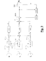
- Fig.3 there is shown a further embodiment with respect to the schematic of Fig.2.
- the sole difference consists in performing the signal demodulation DEM after the sum node SUM.
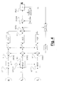
- Fig.4 there is shown still a furter embodiment of the present invention.
- the difference with respect to the embodiment of Fig.2 lies in that the demodulation occurs through two different carrier recovery circuits (DEM1, DEM2), respectively located downstream and upstream of the sum node SUM.
- DEM1, DEM2 carrier recovery circuits
- Fig.5 there is shown a still furter embodiment of the present invention.
- the demodulation of the signal is performed upstream of the sum node SUM through a free oscillator OL and downstream of the sum node utilizing a conventional carrier recovery circuit.
Landscapes
- Engineering & Computer Science (AREA)
- Computer Networks & Wireless Communication (AREA)
- Signal Processing (AREA)
- Power Engineering (AREA)
- Radio Transmission System (AREA)
- Synchronisation In Digital Transmission Systems (AREA)
- Cable Transmission Systems, Equalization Of Radio And Reduction Of Echo (AREA)
Abstract
Description
- Fig. 1 shows the basic diagram of an XPIC;
- Fig. 2 shows the basic diagram of a complete receiving apparatus devoted to the cancellation, in the case at issue, of two generic co-channel interferers;
- Fig. 3 shows only one receive branch and represents a variant with respect to the basic diagram of Fig. 2, with the demodulation circuits located downstream of the cancellation circuits;
- Fig. 4 shows only one receive branch and represents a further variant with respect to the basic diagram of Fig. 2, with the demodulation circuits located both upstream and downstream of the cancellation circuits;
- Fig. 5 shows only one receive branch and represents a further variant with respect to the basic diagram of Fig. 2 wherein the signal demodulation is performed upstream of the sum node by means of a free oscillator and downstream thereof by means of a carrier recovery circuit; and
- Fig. 6 shows (for a single receive branch) the basic diagram of the space-diversity signal combination along with the cancellation of two co-channel interferers.
Claims (12)
- Method for realizing, in a radio transmission system, a carrier synchronization and for cancelling one or more interfering signals (I1 , I2, I3 ) of co - channel type from a received main signal (H), characterized by comprising the steps of:performing a synchronous down - conversion of the received main signal (H) and of each of the interfering signals (I 1 I 2, I 3) to obtain respective intermediate frequency signals (4, 5, 6); andperforming a synchronous demodulation of the intermediate frequency signals (4, 5, 6) so obtained.
- Method according to claim 1, characterized in that said received main signal comprises two or more space and/or angle - diversity received signals (H main, H diversity).
- Method according to claim 1 or 2, characterized by comprising the steps ofequalizing the received main signal (H; Hmain , Hdiversity ) and the one or more interfering signals (I 1 , I 2 , I 3 ) to obtain respective equalized signals; andsumming (SUM) the respective equalized signals to obtain a sum signal (13), wherein the signal synchronous demodulation step is performed upstream of the equalization step by means of suitable carrier recovery circuit utilizing the sum signal (13) and a decided data (14) at the output of a decision circuit (DEC).
- Method according to claim 1 or 2, characterized by comprising the steps ofequalizing the received main signal (H; Hmain , Hdiversity ) and the one or more interfering signals (I 1 , I 2, I 3) to obtain respective equalized signals; andsumming (SUM) the respective equalized signals to obtain a sum signal (13), wherein the signal synchronous demodulation step is performed downstream of the equalization step by means of suitable carrier recovery circuit utilizing the sum signal (13) and a decided data (14) at the output of a decision circuit (DEC).
- Method according to claim 1 or 2, characterized by comprising the steps ofequalizing the received main signal (H; Hmain , Hdiversity ) and the one or more interfering signals (I 1 , I 2, I 3) to obtain respective equalized signals; andsumming (SUM) the respective equalized signals to obtain a sum signal (13), wherein the signal synchronous demodulation step is performed upstream of the equalization step by means of a first carrier recovery circuit utilizing the sum signal (13) and a decided data (14) at the output of a decision circuit (DEC) and downstream of the equalization step by means of a second carrier recovery circuit utilizing the sum signal (13) and a decided data (14) at the output of the decision circuit (DEC).
- Method according to claim 1 or 2, characterized by comprising the steps ofequalizing the received main signal (H; Hmain , Hdiversity ) and the one or more interfering signals (I 1 , I 2, I 3) to obtain respective equalized signals; andsumming (SUM) the respective equalized signals to obtain a sum signal (13), wherein the signal synchronous demodulation step is performed downstream of the equalization step by means of a carrier recovery circuit utilizing the sum signal (13) and a decided data (14) at the output of a decision circuit (DEC) and upstream of the equalization step by means of a free oscillator (OL).
- Device for realizing, in a radio transmission system, a carrier synchronization and for cancelling one or more co - channel interfering signals (l1 , l2, l3 ) from a received main signal (H), characterized by comprising :means (LO, RF/IF) for performing a synchronous down - conversion of the received main signal (H) and of each of the one or more interfering signals (l1, l2, l3) to obtain respective intermediate frequency signals (4,5,6); andmeans for performing a syncronous demodulation of the intermediate frequency signals (4,5,6) so obtained.
- Device according to claim 7, characterized in that said received main signal (H) comprises two or more space and/or angle - diversity received signals (Hmain Hdiversity ).
- Device according to claim 7 or 8, characterized by further comprising:equalizers (EQ1, EQ2, EQ3, EQ4) for equalizing the received main signal (H; Hmain Hdiversity ) and the one or more interfering signals (l1, l2, l3 ) to obtain respective equalized signals; andan adder (SUM) for summing the respective equalized signals and obtaining a sum signal (13), wherein the means for performing the signal synchronous demodulation step operate upstream of said equalizers and comprise a carrier recovery circuit utilizing the sum signal (13) and a decided data (14), at the output of a decision circuit (DEC).
- Device according to claim 7 or 8, characterized by further comprising:equalizers (EQ1, EQ2, EQ3, EQ4) for equalizing the received main signal (H; Hmain , Hdiversity ) and the two or more interfering signals (l1 , l2, l3 ) to obtain respective equalized signals; andan adder (SUM) for summing the respective equalized signals and obtaining a sum signal (13), wherein the means for performing the signal synchronous demodulation step operate downstream of the equalization step and comprise a carrier recovery circuit utilizing the sum signal (13) and a decided data (14), at the output of a decision circuit (DEC).
- Device according to claim 7 or 8, characterized by further comprising:equalizers (EQ1, EQ2, EQ3, EQ4) for equalizing the received main signal (H; Hmain, Hdiversity ) and the one or more interfering signals (l1 , l2, l3 ) to obtain respective equalized signals; andan adder (SUM) for summing the respective equalized signals and obtaining a sum signal (13), wherein the means for performing the signal synchronous demodulation step operate upstream of the equalization step and comprise a first carrier recovery circuit utilizing the sum signal (13) and a decided data (14), at the output of a decision circuit (DEC) and downstream of the equalization step and comprise a second carrier recovery circuit utilizing the sum signal (13) and a decided data (14), at the output of a decision citcuit (DEC).
- Device according to claim 7 or 8, characterized by further comprising:equalizers (EQ1, EQ2, EQ3, EQ4) for equalizing the received main signal (H; Hmain Hdiversity ) and the one or more interfering signals (l1 , l2, l3 ) to obtain respective equalized signals; andan adder (SUM) for summing the respective equalized signals and obtaining a sum signal (13), wherein the means for performing the signal synchronous demodulation step operate downstream of the equalization step and comprise a second carrier recovery circuit utilizing the sum signal (13) and a decided data (14), at the output of a decision circuit (DEC) and upstream of the equalization step and comprise a free oscillator (OL).
Applications Claiming Priority (2)
| Application Number | Priority Date | Filing Date | Title |
|---|---|---|---|
| IT2002MI000371A ITMI20020371A1 (en) | 2002-02-26 | 2002-02-26 | SYNCHRONIZATION AND CANCELLATION OF TWO OR MORE INTERFERING SIGNALS IN RADIO TRANSMISSIONS WITH FREQUENCY REUSE |
| ITMI20020371 | 2002-02-26 |
Publications (2)
| Publication Number | Publication Date |
|---|---|
| EP1339171A2 true EP1339171A2 (en) | 2003-08-27 |
| EP1339171A3 EP1339171A3 (en) | 2008-07-30 |
Family
ID=11449366
Family Applications (1)
| Application Number | Title | Priority Date | Filing Date |
|---|---|---|---|
| EP03290386A Withdrawn EP1339171A3 (en) | 2002-02-26 | 2003-02-18 | Method and device for synchronization and cancellation of a plurality of interfering signals in radio transmission with frequency reuse |
Country Status (3)
| Country | Link |
|---|---|
| US (1) | US7130605B2 (en) |
| EP (1) | EP1339171A3 (en) |
| IT (1) | ITMI20020371A1 (en) |
Cited By (1)
| Publication number | Priority date | Publication date | Assignee | Title |
|---|---|---|---|---|
| EP1708381A1 (en) * | 2005-03-31 | 2006-10-04 | Siemens Mobile Communications S.p.A. | Cross-polarization transmission system with asynchronous receivers |
Families Citing this family (10)
| Publication number | Priority date | Publication date | Assignee | Title |
|---|---|---|---|---|
| WO2007088493A1 (en) * | 2006-01-31 | 2007-08-09 | Nxp B.V. | Fm radio receiver |
| US8095088B2 (en) | 2007-05-17 | 2012-01-10 | Harris Stratex Networks Operating Corporation | Compact wide dynamic range transmitter for point to point radio |
| US8395256B2 (en) * | 2007-02-02 | 2013-03-12 | Harris Stratex Networks Operating Corporation | Packaging for low-cost, high-performance microwave and millimeter wave modules |
| US7782765B2 (en) | 2007-01-22 | 2010-08-24 | Harris Stratex Networks Operating Corporation | Distributed protection switching architecture for point-to-point microwave radio systems |
| US8275071B2 (en) * | 2007-05-17 | 2012-09-25 | Harris Stratex Networks Operating Corporation | Compact dual receiver architecture for point to point radio |
| EP2112772B1 (en) * | 2008-04-24 | 2016-08-31 | Alcatel Lucent | Method for reducing interference in a radio network equipment and equipment performing the method |
| US8615055B2 (en) * | 2009-03-30 | 2013-12-24 | Telefonaktiebolaget L M Ericsson (Publ) | Communication between modems in XPIC configuration for wireless applications |
| CN101800678B (en) * | 2010-03-12 | 2012-05-23 | 华为技术有限公司 | Microwave transmission method, device and system applying CCDP and XPIC |
| EP2560306A4 (en) * | 2010-04-15 | 2016-03-23 | Nec Corp | Cross polarization interference compensation device, cross polarization interference compensation method and program |
| WO2015149373A1 (en) * | 2014-04-04 | 2015-10-08 | 华为技术有限公司 | Same frequency interference cancellation method, device and system |
Citations (1)
| Publication number | Priority date | Publication date | Assignee | Title |
|---|---|---|---|---|
| US4757319A (en) | 1986-05-06 | 1988-07-12 | Siemens Aktiengesellschaft | Adaptive depolarization-interference-compensator |
Family Cites Families (12)
| Publication number | Priority date | Publication date | Assignee | Title |
|---|---|---|---|---|
| US4577330A (en) * | 1984-04-19 | 1986-03-18 | At&T Bell Laboratories | Cross-polarization interference cancellation arrangement for digital radio channels |
| US4723321A (en) * | 1986-11-07 | 1988-02-02 | American Telephone And Telegraph Company, At&T Bell Laboratories | Techniques for cross-polarization cancellation in a space diversity radio system |
| DE69228649T2 (en) * | 1991-11-18 | 1999-08-12 | Nec Corp., Tokio/Tokyo | Automatic equalizer for effective compensation of neighboring symbol interference and cross-polarization interference in the case of double co-channel polarization |
| US5710799A (en) * | 1992-06-01 | 1998-01-20 | Fujitsu Limited | Cross polarization interference canceler and cross polarization interference eliminating apparatus using the same |
| JP2780576B2 (en) * | 1992-08-05 | 1998-07-30 | 日本電気株式会社 | Interference wave canceller |
| US5818517A (en) * | 1993-11-12 | 1998-10-06 | Northern Telecom Limited | Broadband interference reduction |
| US5442663A (en) * | 1994-04-22 | 1995-08-15 | Loral Aerospace Corp. | Residual carrier adaptive cross-polarization equalizer |
| JP3616706B2 (en) * | 1997-06-19 | 2005-02-02 | 富士通株式会社 | Demodulator with cross-polarization interference compensation function |
| DE19926658A1 (en) * | 1999-06-11 | 2000-12-14 | Bosch Gmbh Robert | Receiver for two orthogonally polarized signals |
| JP3859909B2 (en) * | 1999-08-20 | 2006-12-20 | 富士通株式会社 | Cross polarization interference canceller and bit shift method for cross polarization interference cancel |
| US6870882B1 (en) * | 1999-10-08 | 2005-03-22 | At&T Corp. | Finite-length equalization over multi-input multi-output channels |
| US6983125B2 (en) * | 2001-09-25 | 2006-01-03 | Qualcomm Incorporated | Method and apparatus for varying the length of an adaptive equalizer based on doppler frequency |
-
2002
- 2002-02-26 IT IT2002MI000371A patent/ITMI20020371A1/en unknown
-
2003
- 2003-02-18 EP EP03290386A patent/EP1339171A3/en not_active Withdrawn
- 2003-02-25 US US10/372,279 patent/US7130605B2/en not_active Expired - Fee Related
Patent Citations (1)
| Publication number | Priority date | Publication date | Assignee | Title |
|---|---|---|---|---|
| US4757319A (en) | 1986-05-06 | 1988-07-12 | Siemens Aktiengesellschaft | Adaptive depolarization-interference-compensator |
Cited By (1)
| Publication number | Priority date | Publication date | Assignee | Title |
|---|---|---|---|---|
| EP1708381A1 (en) * | 2005-03-31 | 2006-10-04 | Siemens Mobile Communications S.p.A. | Cross-polarization transmission system with asynchronous receivers |
Also Published As
| Publication number | Publication date |
|---|---|
| EP1339171A3 (en) | 2008-07-30 |
| ITMI20020371A0 (en) | 2002-02-26 |
| US7130605B2 (en) | 2006-10-31 |
| ITMI20020371A1 (en) | 2003-08-26 |
| US20030162522A1 (en) | 2003-08-28 |
Similar Documents
| Publication | Publication Date | Title |
|---|---|---|
| JP5317021B2 (en) | Wireless communication system, receiving device, transmitting device, wireless communication method, receiving method, and transmitting method | |
| US6839379B1 (en) | Adaptive DS-CDMA multi-user receiver with diversity combining for interference cancellation | |
| US6819943B2 (en) | Spatial spectral efficiency for wireless rings and network of links in millimeter wave (MMW) communication systems | |
| US9083413B2 (en) | Method for reducing interference in a radio network equipment and equipment performing the method | |
| US7130605B2 (en) | Method and device for synchronization and cancellation of a plurality on interfering signals in radio transmission with frequency reuse | |
| RU2439826C2 (en) | Radio transmission system and method for compensating for cross-talk | |
| EP1365519B1 (en) | Interference erasing system with independent receivers | |
| EP4681351A1 (en) | Transmitter for a satellite communication system | |
| AU2020311876B2 (en) | System and method for cancelling strong signals from combined weak and strong signals in communications systems | |
| US20240048410A1 (en) | Pilot-less channel estimation and evaluation for los-mimo microwave radio links | |
| IL276847A (en) | Receiver and method for receiving a combination signal using separate in-phase and quadrature components | |
| EP0902556B1 (en) | Telecommunication system and method using radio link | |
| Soria et al. | Performance comparison of 2× 2 and 4× 4 V-BLAST and Alamouti MIMO systems | |
| KR100719607B1 (en) | Interference cancellation method of dual polarization applied to the same frequency channel in mobile wireless communication system and system | |
| EP2015468A1 (en) | Baseband combiner for digital radio links | |
| WO2017161930A1 (en) | Accurate cross-phase estimation for dual polarized microwave transceiver | |
| EP4500709A1 (en) | Los-mimo microwave radio link reconfiguration for variable number of mimo data streams | |
| WO2023191669A1 (en) | Los-mimo microwave radio link channel estimation for rank deficient channels | |
| JP2025138172A (en) | wireless communication system | |
| EP1708381B1 (en) | Cross-polarization transmission system with asynchronous receivers | |
| Savazzi et al. | Channel parameter acquisition in MIMO LOS systems for high capacity microwave links | |
| WO2002017508A2 (en) | Digital receiver and method for symbol detection in a spread spectrum signal | |
| US20250030449A1 (en) | A successive interference cancellation receiver for line-of-sight multiple-input multiple-output receivers | |
| JP2025122325A (en) | wireless communication system | |
| Gävert | On pilot-based estimation of phase noise |
Legal Events
| Date | Code | Title | Description |
|---|---|---|---|
| PUAI | Public reference made under article 153(3) epc to a published international application that has entered the european phase |
Free format text: ORIGINAL CODE: 0009012 |
|
| AK | Designated contracting states |
Designated state(s): AT BE BG CH CY CZ DE DK EE ES FI FR GB GR HU IE IT LI LU MC NL PT SE SI SK TR |
|
| AX | Request for extension of the european patent |
Extension state: AL LT LV MK RO |
|
| RAP1 | Party data changed (applicant data changed or rights of an application transferred) |
Owner name: ALCATEL LUCENT |
|
| PUAL | Search report despatched |
Free format text: ORIGINAL CODE: 0009013 |
|
| AK | Designated contracting states |
Kind code of ref document: A3 Designated state(s): AT BE BG CH CY CZ DE DK EE ES FI FR GB GR HU IE IT LI LU MC NL PT SE SI SK TR |
|
| AX | Request for extension of the european patent |
Extension state: AL LT LV MK RO |
|
| 17P | Request for examination filed |
Effective date: 20090130 |
|
| 17Q | First examination report despatched |
Effective date: 20090305 |
|
| AKX | Designation fees paid |
Designated state(s): AT BE BG CH CY CZ DE DK EE ES FI FR GB GR HU IE IT LI LU MC NL PT SE SI SK TR |
|
| GRAP | Despatch of communication of intention to grant a patent |
Free format text: ORIGINAL CODE: EPIDOSNIGR1 |
|
| STAA | Information on the status of an ep patent application or granted ep patent |
Free format text: STATUS: THE APPLICATION IS DEEMED TO BE WITHDRAWN |
|
| 18D | Application deemed to be withdrawn |
Effective date: 20100729 |