EP1339156A2 - Electric rotary machine having bobbins with thin-walled extensions of flange - Google Patents
Electric rotary machine having bobbins with thin-walled extensions of flange Download PDFInfo
- Publication number
- EP1339156A2 EP1339156A2 EP03251082A EP03251082A EP1339156A2 EP 1339156 A2 EP1339156 A2 EP 1339156A2 EP 03251082 A EP03251082 A EP 03251082A EP 03251082 A EP03251082 A EP 03251082A EP 1339156 A2 EP1339156 A2 EP 1339156A2
- Authority
- EP
- European Patent Office
- Prior art keywords
- rotary machine
- stator ring
- flange
- bobbin
- thin
- Prior art date
- Legal status (The legal status is an assumption and is not a legal conclusion. Google has not performed a legal analysis and makes no representation as to the accuracy of the status listed.)
- Withdrawn
Links
Images




Classifications
-
- H—ELECTRICITY
- H02—GENERATION; CONVERSION OR DISTRIBUTION OF ELECTRIC POWER
- H02K—DYNAMO-ELECTRIC MACHINES
- H02K5/00—Casings; Enclosures; Supports
- H02K5/04—Casings or enclosures characterised by the shape, form or construction thereof
- H02K5/08—Insulating casings
-
- H—ELECTRICITY
- H02—GENERATION; CONVERSION OR DISTRIBUTION OF ELECTRIC POWER
- H02K—DYNAMO-ELECTRIC MACHINES
- H02K1/00—Details of the magnetic circuit
- H02K1/06—Details of the magnetic circuit characterised by the shape, form or construction
- H02K1/12—Stationary parts of the magnetic circuit
- H02K1/14—Stator cores with salient poles
- H02K1/146—Stator cores with salient poles consisting of a generally annular yoke with salient poles
- H02K1/148—Sectional cores
-
- H—ELECTRICITY
- H02—GENERATION; CONVERSION OR DISTRIBUTION OF ELECTRIC POWER
- H02K—DYNAMO-ELECTRIC MACHINES
- H02K3/00—Details of windings
- H02K3/46—Fastening of windings on the stator or rotor structure
- H02K3/52—Fastening salient pole windings or connections thereto
- H02K3/521—Fastening salient pole windings or connections thereto applicable to stators only
- H02K3/522—Fastening salient pole windings or connections thereto applicable to stators only for generally annular cores with salient poles
-
- H—ELECTRICITY
- H02—GENERATION; CONVERSION OR DISTRIBUTION OF ELECTRIC POWER
- H02K—DYNAMO-ELECTRIC MACHINES
- H02K15/00—Processes or apparatus specially adapted for manufacturing, assembling, maintaining or repairing of dynamo-electric machines
- H02K15/04—Processes or apparatus specially adapted for manufacturing, assembling, maintaining or repairing of dynamo-electric machines of windings prior to their mounting into the machines
-
- H—ELECTRICITY
- H02—GENERATION; CONVERSION OR DISTRIBUTION OF ELECTRIC POWER
- H02K—DYNAMO-ELECTRIC MACHINES
- H02K15/00—Processes or apparatus specially adapted for manufacturing, assembling, maintaining or repairing of dynamo-electric machines
- H02K15/12—Impregnating, moulding insulation, heating or drying of windings, stators, rotors or machines
-
- H—ELECTRICITY
- H02—GENERATION; CONVERSION OR DISTRIBUTION OF ELECTRIC POWER
- H02K—DYNAMO-ELECTRIC MACHINES
- H02K2203/00—Specific aspects not provided for in the other groups of this subclass relating to the windings
- H02K2203/12—Machines characterised by the bobbins for supporting the windings
Definitions
- the present invention relates to an electric rotary machine (hereinafter referred to as "rotary machine,” or occasionally “motor” as appropriate), and more particularly to a radial gap type rotary machine comprising an armature with discrete salient poles.
- a stator armature structured such that a plurality of ring-shaped yoke pieces, which are made of a soft magnetic plate, such as a silicon steel plate, and which each have a plurality of pole tooth portions protruding radially, are stacked in the axial direction, since each of the ring-shaped yoke pieces is punched out integrally with the plurality of pole tooth portions as a single piece (the armature composed of the ring-shaped yoke pieces thus structured is hereinafter referred to as "integral armature" as appropriate), pole teeth each composed of a stack number of pole tooth portions are not partitioned structurally and therefore a resultant armature will have superior magnetic efficiency (low reluctance).
- One example of the discrete armature is manufactured such that pole tooth portions are dismembered off its main body portion of an integral armature, a wire is wound around each of the dismembered pole tooth portions thereby constituting each salient pole portion, and that the pole tooth portions each with a wire wound therearound, namely, the salient pole portions are rejoined to the main body portion by laser-welding, or the like.
- the armature thus structured has a disadvantage that the integral armature has to be first sectioned and later reassembled, thereby requiring an additional time. Also, when the pole tooth portions each with a winding (salient poles) are rejoined to the main body portion, the stack layers of the both portions have to be matched with each other, and therefore it is required that respective portions be held together by a well-maintained tool and surely welded plate by plate for ensuring precision, which results in decreased workability. And, joints (welded portions) deteriorate significantly in mechanical strength and magnetic characteristics.
- a radial gap type rotary machine including a stator which comprises: a discrete armature including a plurality of discrete salient poles, and a cylindrical pole tooth ring for connecting the salient poles to one another magnetically and mechanically; and a cylindrical stator ring adapted to decrease leakage flux resulting from magnetic discontinuity.
- Fig. 10 is a partial cross-sectional view of a conventional rotary machine with a discrete armature viewed from the axial direction. Illustrated in Fig. 10 are: salient poles 106, an armature assembly 110, a flange 12, a rotor assembly 20, a shaft 21, pole teeth 134, bobbins 136, bobbin flanges 136b and 136c, coil winding portions 136g, magnetic wires 138, a molding resin 60, and a stator ring 100.
- 2001-238377 has a pole tooth ring for positioning and fixing salient poles, but the pole tooth ring is not essential for the prevent invention and is omitted in Fig. 10 for ease of understanding. However, it is noted that the present invention can be applied to a rotary machine having the pole tooth ring.
- the bobbin 136 which holds a pole tooth comprising a plurality of thin steel plates stacked, has its flanges 136b and 136c respectively on its both ends sandwiching the coil winding portion 136g.
- the bobbin flanges 136b and 136c are dimensioned to be larger than the coil winding thickness so as to keep the magnet wire 138 braided in good shape.
- the molding resin 60 is injected between the salient poles 106, whereby the salient poles 106 and the magnet wires 138 are fixed securely.
- the circumferential dimension of the bobbin flange 136b positioned toward the stator ring 100 is usually determined according to the coil winding thickness.
- the magnet wire 138 receives a stress due to the expansion and contraction of the molding resin 60 injected between the salient poles 106, and may become unbraided at its outer turns when the bobbin flange 136b is conventionally dimensioned, which allows a part of the magnet wire 138 to get in direct contact with the stator ring 100 of a steel plate, possibly causing an insulation failure.
- the bobbin flange 136b has a dimensional problem, which will be described with reference to Figs.11A, 11B and 12.
- Fig. 11A is a cross-sectional view of a bobbin of the salient pole 106, in which the bobbin flange 136b positioned toward the stator ring 100 is dimensioned to the outside dimension of a coil
- Fig. 11B is a cross-sectional view of a bobbin of a salient pole 206, in which a bobbin flange 236b positioned toward the stator ring 100 is dimensioned to be larger than the outside dimension of a coil.
- the bobbin flange 236b dimensioned to be larger than the outside dimension of a coil is forced to be located closer to another bobbin flange 236c due to the stator ring 100 arcing, thereby decreasing a winding space for a magnet wire 238.
- Fig. 12 is an explanatory view of the problem of the seeming solution.
- a salient pole 306 has a bobbin with a bobbin flange 336b located toward the stator ting 100 (not shown in Fig. 12).
- the bobbin flange 336b has an increased dimension, and is arced to follow the inner circumferential surface of the stator ring 100.
- a coil winding portion 336g defined by a space between the bobbin flange 336 b and another bobbin flange 336c can be increased by the dimension S in the length direction.
- the inwardly-overhanging (downwardly in the figure) ends of the bobbin flange 336b stand in the way when a magnet wire 338 is wound on the bobbin, making the winding operation very difficult, and can touch the magnet wire 338 causing a trouble. Accordingly, the increased dimension S cannot be fully utilized due to the existence of the downwardly-overhanging ends of the bobbin flange 336b.
- the rotary machine shown in Fig. 10 is structured such that the rotor assembly 20 is disposed at the center of the stator ring 100, and a plurality (six in the figure) of salient poles 106 are arrayed circumferentially between the stator ring 100 and the rotor assembly 20.
- This structure causes it that an open space, into which the molding resin 60 is poured, is larger toward the stator ring 100 than toward the rotor assembly 20.
- the above described problem produces an additional open space proportionate to the decreased coil winding portion, which increases the amount of the molding resin 60 thereby pushing up the material cost and increasing the injecting time, especially in case of a large size rotary machine.
- the present invention has been made in the light of the above problems, and it is an object of the invention to provide a rotary machine, in which a magnet wire is free from contact with a stator ring, the space factor of a coil is increased, and the amount of a molding resin to be injected inside the stator ring is decreased.
- a rotary machine includes a stator comprising: a stator ring thereby forming a magnetic circuit; a plurality of salient poles each having a pole tooth, disposed inside the stator ring, and fixed by a molding resin injected inside the stator ring; and a plurality of bobbins each constituting the salient pole, adapted to lodge the pole tooth fitted thereinto and to have a magnet wire wound thereon, and each having its outward-positioned flange in contact with the stator ring, wherein the outward-positioned flange has two flexible thin-walled extensions at its respective ends thereby securely holding the wound magnet wire in place.
- a resin compartment is formed at the end of one of the two thin-walled extensions.
- any part of the resin compartment is positioned behind the plane of the inner wall face of the bobbin flange before assembly.
- the resin compartment is hollow.
- the flexible thin-walled extensions which are adapted to hold the magnet wire wound in place thereby preventing the magnet wire from making contact with the stator ring, stay unbent before assembly and are bent during assembly, whereby the winding operation is not hindered improving the production efficiency and also the coil winding portion can be successfully increased improving the space factor.
- the resin compartment works to reduce the open space in the stator ring to be filled by the molding resin, thereby decreasing the amount of the molding resin and reducing the time for injecting the molding resin.
- Figs. 1 and 2 show a structure of a three-phase inner rotor type brushless DC motor with six salient poles and eight rotor magnetic poles, as an embodiment of the present invention, wherein illustrated are: salient poles 6, an armature assembly 10, flanges 12 and 13, a rotor assembly 20, a shaft 21, a sleeve 22, a rotor field magnet 23, a rotor position detecting magnet 23a, a spacer 24, a ball bearing 25, a sleeve bearing 26, a preload spring holder 27, a preload spring 28, pole teeth 34, pole tooth end portions 34a, bobbins 36, bobbin flanges 36b and 36c, coil winding portions 36g, resin compartments 36e, bobbin flange thin-walled extensions 36f and 36i having flexibility, magnet wires 38, terminal pins 40, a printed circuit board 51, a Hall sensor 52, connector terminals 53, a connector 57, a molding resin 60, and a cylindrical stator ring
- the embodiment here refers to a so-called integrally resin-molded armature assembly structured such that a resin is filled inside an armature assembly except a portion where a rotor field magnet is received.
- the brushless DC motor generally comprises: the armature assembly 10; the two flanges 12 and 13 arranged respectively at both axial ends of the armature assembly 10; and the rotor assembly 20 rotatably disposed inside the armature assembly 10.
- the armature assembly 10 includes: the stator ring 100 as its outer circumference; and six of the salient poles 6 each extending radially, and arrayed circumferentially at an even angular interval of 60 degrees.
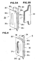
- the salient poles 6 are each structured such that the pole tooth 34 (Fig. 3B) composed of seven surface-insulated magnetic steel plates stacked on one another, each plate having a thickness of 0.5 mm and punched out to be substantially T-shaped, has its T-letter's vertical (oriented horizontal in the figure) bar portion inserted into a rectangular hole 36a of the bobbin 36 (Fig. 3A) and such that the wire 38 is wound on the coil winding portion 36g defined between the bobbin flanges 36b and 36c as shown in Fig. 4.
- the terminations of the magnet wire 38 are bound around respective terminal pins 40 attached to the lower end of the bobbin flange 36c.
- the pole tooth 34 is dimensioned so as to protrude by a predetermined dimension overall from the surface of the bobbin flange 36b when fitted into the hole 36a of the bobbin 36.
- the pole tooth 34 may alternatively be made of a soft magnetic material such as a ceramic molding formed by sintering a soft magnetic powder, and a metallurgic molding formed by sintering a soft magnetic material composed of micro-powder of surface-insulated pure iron.
- the pole tooth 34 made of a different soft magnetic steel material containing Fe-Ni-Cr series steel not only keeps a high permeability but also has a relatively high electrical resistance thereby reducing its eddy current loss, and at the same time is free from corrosion without rustproof treatment thus being suitable for use in extreme environments such as automotive application.
- the bobbin flange 36c has, on each of its both sides, two notches 36d, 36d forming resin injection holes for injecting the molding resin 48 through.
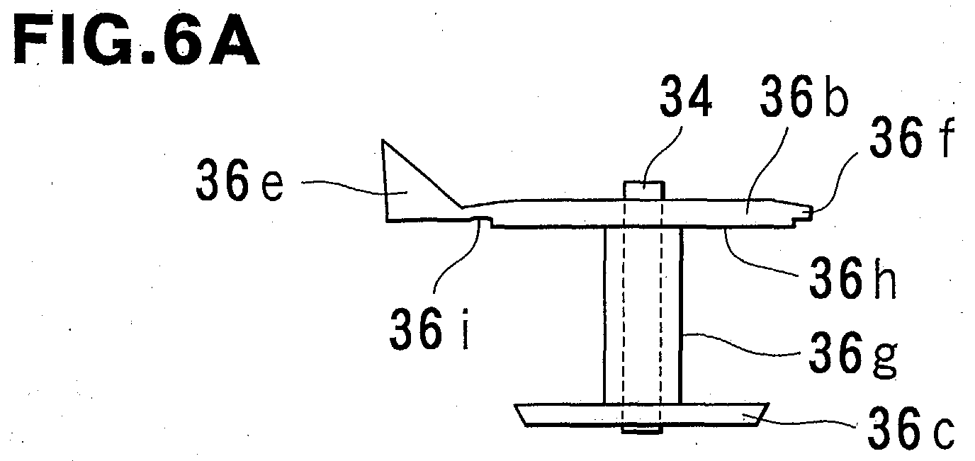
- the bobbin flange 36b has a thin-walled extension 36f at one end thereof, and a thin-walled extension 36i and a resin compartment 36e at the other end.
- the thin-walled extensions 36f and 36i, and the resin compartment 36e may be formed of the same material as the other portions of the bobbin 36, for example, resin.
- the bobbin flange 36b of the present invention has its width increased for the dimensions of the thin-walled extensions 36f and 36i, and the resin compartment 36e, whereby the magnet wire 38 wound is prevented from becoming unbraided to get in contact with the stator ring 100 while assembling the rotary machine.
- Figs. 5A and 5B which in combination constitute an exploded view of the armature assembly 10 shown in Fig. 1.
- any component parts corresponding to those in Figs. 1 to 4 are denoted by the same reference numerals, and a detailed description thereof will be omitted.
- the stator ring 100 shown in Fig. 5B is a hollow cylinder of soft magnetic steel and has a notch 100a for accommodating the connector 57 (see Fig. 1).
- the stator ring 100 is put over the salient poles 6 shown in Fig. 5A, whereby a magnetic circuit is formed.
- a pole tooth ring which is used in a rotary machine disclosed in Japanese Patent Application Laid-open No. 2001-238377, is eliminated, but the present invention is not limited thereto but may be applied to the rotary machine using the pole tooth ring.
- the thin-walled extension 36i is formed between bobbin flange 36b and the resin compartment 36e, and is adapted to bend flexibly. Also, the thin-walled extension 36f is adapted to bend flexibly.
- the wire magnet 38 is wound on the coil winding extension 36g of the bobbin 36, the thin-walled extensions 36f and 36i stay unbent as shown in Fig. 6A thereby not hindering the winding operation, thus the magnet wire 38 can be fully wound all the way up to a flange inner face 36h of the bobbin flange 36b.
- the resin compartment 36e will be described with reference to Fig. 7.
- the bobbin flange 36b is provided integrally with the resin compartment 36e, which is a hollow-triangular prism having two closed end faces, one open flat (in section) side face 36k and two closed flat side faces 36m and 36n, and which extends from the very end of the thin-walled extension 36i such that the side face 36n is positioned behind the plane of the flange inner face 36h.
- the open space to be filled with the molding resin 60 is reduced for the volume of the prism compared to the conventional rotary machine shown in Fig. 1, thereby decreasing the amount of the molding resin 60 to be injected in the stator ring 100 thus reducing the material cost (resin cost), and reducing the time for injection resulting in improved production efficiency. Also, this enables a small inexpensive molding machine to be used.
- the hollow-triangular prism as shown in Fig. 7 is used as the resin compartment 36e but the present invention is not limited thereto but the present invention may alternatively use, for example, a resin compartment 436e as shown in Fig. 8 showing a second embodiment.
- the resin compartment 436e is continuous with a bobbin flange via a thin-walled portion 436i, and is a hollow-semicircular prism having two closed end faces, one open arced (in section) side face 436k, one closed arced face 436m and one closed flat face 436n.
- FIGS. 9A and 9B show a bobbin 536, bobbin flanges 536b and 536c, a coil winding portion 536g, a flange inner face 536h of the bobbin flange 536b, thin-walled extensions 536f and 536i, and a resin compartment 536j.
- the resin compartment 536j is formed such that the thin-walled portion 536i is extended thereby preventing the magnet wire 38 (not shown in Figs. 9A and 9B) from becoming unbraided, and keeping the magnet wire 38 free from contact with the stator ring.
- This resin compartment 536j has its inside face positioned flush with or behind the flange inner face 536f thereby not hindering the winding operation, and is flexibly bent at the thin-walled extension 536i when the salient pole assembly is housed in the stator ring thereby not taking up an unnecessary space unlike the bobbin flange 236b in the conventional rotary machine shown in Fig. 11B.
Landscapes
- Engineering & Computer Science (AREA)
- Power Engineering (AREA)
- Insulation, Fastening Of Motor, Generator Windings (AREA)
- Iron Core Of Rotating Electric Machines (AREA)
- Windings For Motors And Generators (AREA)
- Permanent Magnet Type Synchronous Machine (AREA)
Abstract
Description
Claims (4)
- An electric rotary machine, in which a stator comprises: a stator ring; a plurality of discrete salient poles each comprising a pole tooth, and disposed inside the stator ring thereby forming a magnetic circuit, and fixed by a molding resin injected inside the stator ring; and a plurality of bobbins each constituting the salient pole, adapted to lodge the pole tooth fitted thereinto and to have a magnet wire wound thereon, and each having its outward-positioned flange in contact with the stator ring, characterized in that the flange of the bobbin has two flexible thin-walled extensions at its respective ends thereby securely holding the wound magnet wire in place.
- An electric rotary machine according to Claim 1, wherein a resin compartment is formed at an end of one of the two thin-walled extensions.
- An electric rotary machine according to Claim 2, wherein any part of the resin compartment is positioned behind a plane of an inner face of the bobbin flange before assembly.
- An electric rotary machine according to Claim 2 or 3, wherein the resin compartment is hollow.
Applications Claiming Priority (2)
| Application Number | Priority Date | Filing Date | Title |
|---|---|---|---|
| JP2002048047A JP3930340B2 (en) | 2002-02-25 | 2002-02-25 | Rotating electric machine |
| JP2002048047 | 2002-02-25 |
Publications (2)
| Publication Number | Publication Date |
|---|---|
| EP1339156A2 true EP1339156A2 (en) | 2003-08-27 |
| EP1339156A3 EP1339156A3 (en) | 2006-03-22 |
Family
ID=27655433
Family Applications (1)
| Application Number | Title | Priority Date | Filing Date |
|---|---|---|---|
| EP03251082A Withdrawn EP1339156A3 (en) | 2002-02-25 | 2003-02-22 | Electric rotary machine having bobbins with thin-walled extensions of flange |
Country Status (3)
| Country | Link |
|---|---|
| US (1) | US6737782B2 (en) |
| EP (1) | EP1339156A3 (en) |
| JP (1) | JP3930340B2 (en) |
Cited By (8)
| Publication number | Priority date | Publication date | Assignee | Title |
|---|---|---|---|---|
| EP1619779A1 (en) * | 2004-07-22 | 2006-01-25 | Moving Magnet Technologies | Electrical Three-Phase Motor |
| WO2007033639A1 (en) * | 2005-09-21 | 2007-03-29 | Temic Automotive Electric Motors Gmbh | Stator for an electric motor and method for production thereof |
| CN103683555A (en) * | 2012-09-19 | 2014-03-26 | 株式会社安川电机 | Stator and rotating electrical machine |
| WO2015071089A3 (en) * | 2013-11-13 | 2015-08-13 | Robert Bosch Gmbh | Electric machine with a potted winding head |
| CN113315290A (en) * | 2021-07-05 | 2021-08-27 | 珠海格力电器股份有限公司 | Motor stator insulation framework assembly, motor stator, motor and air conditioner |
| GB2604034A (en) * | 2021-02-19 | 2022-08-24 | Electrified Automation Ltd | Electric machine, rotor and stator |
| DE102022103713A1 (en) | 2022-02-17 | 2023-08-17 | Voith Patent Gmbh | Pole assembly for constructing a pole ring for an electrical machine |
| GB2616461A (en) * | 2022-03-10 | 2023-09-13 | Protean Electric Ltd | A bobbin |
Families Citing this family (24)
| Publication number | Priority date | Publication date | Assignee | Title |
|---|---|---|---|---|
| US7078843B2 (en) | 2003-09-05 | 2006-07-18 | Black & Decker Inc. | Field assemblies and methods of making same |
| US7205696B2 (en) | 2003-09-05 | 2007-04-17 | Black & Decker Inc. | Field assemblies having pole pieces with ends that decrease in width, and methods of making same |
| US7233091B2 (en) | 2003-09-05 | 2007-06-19 | Black & Decker Inc. | Electric motor with field assemblies having core pieces with mating features |
| US7211920B2 (en) | 2003-09-05 | 2007-05-01 | Black & Decker Inc. | Field assemblies having pole pieces with axial lengths less than an axial length of a back iron portion and methods of making same |
| KR100653931B1 (en) * | 2005-01-17 | 2006-12-05 | 주식회사 이엠에프 세이프티 | Ultra Low Frequency Small 3-Axis Magnetic Field Measurement Probe |
| EP2562912A1 (en) | 2005-03-07 | 2013-02-27 | Black & Decker Inc. | Power Tools with Motor Having a Multi-Piece Stator |
| JP4863061B2 (en) | 2006-05-12 | 2012-01-25 | 株式会社ジェイテクト | Electric motor |
| DE102008012680A1 (en) * | 2008-03-05 | 2009-09-17 | Minebea Co., Ltd. | Electric machine |
| US7569965B2 (en) * | 2007-02-13 | 2009-08-04 | Sanyo Denki Co., Ltd. | Stator for motor |
| JP5282780B2 (en) * | 2010-12-09 | 2013-09-04 | 株式会社安川電機 | Rotating electric machine |
| CA2802466A1 (en) * | 2012-01-17 | 2013-07-17 | Regal Beloit America, Inc. | Electric motor |
| US20130207506A1 (en) * | 2012-02-13 | 2013-08-15 | Fang-Fu Chang | Insulated structure of shield type motor coil |
| WO2014011783A1 (en) * | 2012-07-11 | 2014-01-16 | Remy Technologies, Llc | Interlocking coil isolators for resin retention in a segmented stator assembly |
| JP5954198B2 (en) * | 2013-01-28 | 2016-07-20 | 株式会社デンソー | Rotating electric machine |
| US10298104B2 (en) * | 2014-04-16 | 2019-05-21 | Power It Perfect, Inc. | Electrical motor and electrical generator device |
| JP6287976B2 (en) * | 2015-06-30 | 2018-03-07 | トヨタ自動車株式会社 | Manufacturing method of stator of rotating electric machine |
| EP3940236B1 (en) * | 2015-12-14 | 2024-11-13 | Pleuger Industries GmbH | Method of constructing a rotor for an electric submersible pump with a one-piece rotor/yoke configuration and resin embedded magnets |
| JP6719052B2 (en) * | 2016-06-23 | 2020-07-08 | パナソニックIpマネジメント株式会社 | Insulator, electric motor, and blower |
| JP6932546B2 (en) * | 2017-05-19 | 2021-09-08 | エドワーズ株式会社 | A vacuum pump, a magnetic bearing device used in the vacuum pump, and an annular electromagnet. |
| JP7001016B2 (en) * | 2017-12-28 | 2022-01-19 | 株式会社デンソー | Wheel drive |
| CN111656648B (en) * | 2018-01-29 | 2021-04-27 | 三菱电机株式会社 | Stator and Motor |
| DE102019202760A1 (en) * | 2019-02-28 | 2020-09-03 | Rolls-Royce Deutschland Ltd & Co Kg | Sealing sleeve for a stator of an electrical machine |
| US12068659B2 (en) | 2019-12-05 | 2024-08-20 | Sharkninja Operating Llc | Diffuser for an electric motor |
| DE102020131410A1 (en) | 2020-11-26 | 2022-06-02 | Nidec Motors & Actuators (Germany) Gmbh | Electric motor with an injection-molded rotor having an axial support for a ball bearing |
Family Cites Families (10)
| Publication number | Priority date | Publication date | Assignee | Title |
|---|---|---|---|---|
| US3339097A (en) * | 1965-08-10 | 1967-08-29 | Eastman Mfg Co Inc | Bobbin and pole construction |
| US3609427A (en) * | 1970-05-13 | 1971-09-28 | Gould Inc | Field coil structure for electric motor |
| FR2384376A1 (en) * | 1977-03-16 | 1978-10-13 | Roshardt Didier | Winding spool construction for split pole motor - is used where spools are joined together at radially outward end by flexible strip |
| GB2172444B (en) * | 1985-03-09 | 1988-08-17 | Asmo Co Ltd | Stator for an electric motor |
| DE9216478U1 (en) * | 1992-12-03 | 1993-01-21 | Maico Elektroapparate-Fabrik GmbH, 7730 Villingen-Schwenningen | Electric motor, especially small motor |
| US5698923A (en) * | 1996-05-24 | 1997-12-16 | Alliedsignal Inc. | Exciter stator insulating bobbin |
| JP3318531B2 (en) * | 1998-08-04 | 2002-08-26 | ミネベア株式会社 | Rotating electric machine and its bearing structure |
| JP3421251B2 (en) * | 1998-08-21 | 2003-06-30 | ミネベア株式会社 | Rotating electric machine and its bobbin |
| JP2001045692A (en) * | 1999-08-03 | 2001-02-16 | Toyoda Mach Works Ltd | Coil-winding structure of motor |
| JP2001238377A (en) * | 2000-02-24 | 2001-08-31 | Minebea Co Ltd | Rotating electric machine |
-
2002
- 2002-02-25 JP JP2002048047A patent/JP3930340B2/en not_active Expired - Fee Related
-
2003
- 2003-02-20 US US10/370,966 patent/US6737782B2/en not_active Expired - Fee Related
- 2003-02-22 EP EP03251082A patent/EP1339156A3/en not_active Withdrawn
Cited By (12)
| Publication number | Priority date | Publication date | Assignee | Title |
|---|---|---|---|---|
| EP1619779A1 (en) * | 2004-07-22 | 2006-01-25 | Moving Magnet Technologies | Electrical Three-Phase Motor |
| FR2873512A1 (en) * | 2004-07-22 | 2006-01-27 | Moving Magnet Tech | THREE-PHASE ELECTRIC MOTOR |
| WO2007033639A1 (en) * | 2005-09-21 | 2007-03-29 | Temic Automotive Electric Motors Gmbh | Stator for an electric motor and method for production thereof |
| CN103683555A (en) * | 2012-09-19 | 2014-03-26 | 株式会社安川电机 | Stator and rotating electrical machine |
| CN103683555B (en) * | 2012-09-19 | 2016-01-20 | 株式会社安川电机 | Stator and electric rotating machine |
| WO2015071089A3 (en) * | 2013-11-13 | 2015-08-13 | Robert Bosch Gmbh | Electric machine with a potted winding head |
| GB2604034A (en) * | 2021-02-19 | 2022-08-24 | Electrified Automation Ltd | Electric machine, rotor and stator |
| GB2604034B (en) * | 2021-02-19 | 2023-05-31 | Electrified Automation Ltd | Electric machine, stator and insulator |
| CN113315290A (en) * | 2021-07-05 | 2021-08-27 | 珠海格力电器股份有限公司 | Motor stator insulation framework assembly, motor stator, motor and air conditioner |
| DE102022103713A1 (en) | 2022-02-17 | 2023-08-17 | Voith Patent Gmbh | Pole assembly for constructing a pole ring for an electrical machine |
| GB2616461A (en) * | 2022-03-10 | 2023-09-13 | Protean Electric Ltd | A bobbin |
| WO2023170377A1 (en) * | 2022-03-10 | 2023-09-14 | Protean Electric Limited | A bobbin |
Also Published As
| Publication number | Publication date |
|---|---|
| JP3930340B2 (en) | 2007-06-13 |
| JP2003250241A (en) | 2003-09-05 |
| US6737782B2 (en) | 2004-05-18 |
| EP1339156A3 (en) | 2006-03-22 |
| US20030160532A1 (en) | 2003-08-28 |
Similar Documents
| Publication | Publication Date | Title |
|---|---|---|
| US6737782B2 (en) | Electric rotary machine having bobbins with thin-walled extensions of flange | |
| EP1345306B1 (en) | Electric rotary machine having positioning ring for securing salient poles in place | |
| EP1128524B1 (en) | Electric rotary machine | |
| US6822356B2 (en) | Electric rotary machine with stator armature including barrier walls | |
| JP3421251B2 (en) | Rotating electric machine and its bobbin | |
| US6815861B2 (en) | Electric rotary machine with armature of discrete salient pole structure | |
| US7279821B2 (en) | Motor | |
| US6812611B2 (en) | Permanent magnet type electric rotating machine | |
| US6194806B1 (en) | Compact cylindrical radial gap type motor | |
| US6717319B2 (en) | Electric rotary machine with armature of discrete salient pole structure | |
| KR100729750B1 (en) | Stepping motor and drive device | |
| EP1394922A1 (en) | Bobbin provided with cover for protecting magnet wire | |
| EP1445851B1 (en) | Motor | |
| EP1901415B1 (en) | Electric rotary machine | |
| EP4300773A1 (en) | Stator and brushless motor | |
| JP3517606B2 (en) | motor | |
| JP2024055348A (en) | Rotating Electric Machine | |
| JP2024055347A (en) | Rotating Electric Machine | |
| JPH0479743A (en) | Small motor bobbin structure |
Legal Events
| Date | Code | Title | Description |
|---|---|---|---|
| PUAI | Public reference made under article 153(3) epc to a published international application that has entered the european phase |
Free format text: ORIGINAL CODE: 0009012 |
|
| AK | Designated contracting states |
Designated state(s): AT BE BG CH CY CZ DE DK EE ES FI FR GB GR HU IE IT LI LU MC NL PT SE SI SK TR |
|
| AX | Request for extension of the european patent |
Extension state: AL LT LV MK RO |
|
| PUAL | Search report despatched |
Free format text: ORIGINAL CODE: 0009013 |
|
| AK | Designated contracting states |
Kind code of ref document: A3 Designated state(s): AT BE BG CH CY CZ DE DK EE ES FI FR GB GR HU IE IT LI LU MC NL PT SE SI SK TR |
|
| AX | Request for extension of the european patent |
Extension state: AL LT LV MK RO |
|
| RIC1 | Information provided on ipc code assigned before grant |
Ipc: H02K 1/14 20060101ALI20060130BHEP Ipc: H02K 3/52 20060101ALI20060130BHEP Ipc: H02K 3/32 20060101AFI20030604BHEP |
|
| 17P | Request for examination filed |
Effective date: 20060512 |
|
| AKX | Designation fees paid |
Designated state(s): DE FR |
|
| 17Q | First examination report despatched |
Effective date: 20081216 |
|
| STAA | Information on the status of an ep patent application or granted ep patent |
Free format text: STATUS: THE APPLICATION IS DEEMED TO BE WITHDRAWN |
|
| 18D | Application deemed to be withdrawn |
Effective date: 20090428 |