EP1339046A2 - Method of magnetic transfer - Google Patents
Method of magnetic transfer Download PDFInfo
- Publication number
- EP1339046A2 EP1339046A2 EP03004211A EP03004211A EP1339046A2 EP 1339046 A2 EP1339046 A2 EP 1339046A2 EP 03004211 A EP03004211 A EP 03004211A EP 03004211 A EP03004211 A EP 03004211A EP 1339046 A2 EP1339046 A2 EP 1339046A2
- Authority
- EP
- European Patent Office
- Prior art keywords
- slave medium
- magnetic field
- magnetic
- transfer
- master information
- Prior art date
- Legal status (The legal status is an assumption and is not a legal conclusion. Google has not performed a legal analysis and makes no representation as to the accuracy of the status listed.)
- Withdrawn
Links
Images


Classifications
-
- G—PHYSICS
- G11—INFORMATION STORAGE
- G11B—INFORMATION STORAGE BASED ON RELATIVE MOVEMENT BETWEEN RECORD CARRIER AND TRANSDUCER
- G11B5/00—Recording by magnetisation or demagnetisation of a record carrier; Reproducing by magnetic means; Record carriers therefor
- G11B5/86—Re-recording, i.e. transcribing information from one magnetisable record carrier on to one or more similar or dissimilar record carriers
-
- G—PHYSICS
- G11—INFORMATION STORAGE
- G11B—INFORMATION STORAGE BASED ON RELATIVE MOVEMENT BETWEEN RECORD CARRIER AND TRANSDUCER
- G11B5/00—Recording by magnetisation or demagnetisation of a record carrier; Reproducing by magnetic means; Record carriers therefor
- G11B5/86—Re-recording, i.e. transcribing information from one magnetisable record carrier on to one or more similar or dissimilar record carriers
- G11B5/865—Re-recording, i.e. transcribing information from one magnetisable record carrier on to one or more similar or dissimilar record carriers by contact "printing"
-
- G—PHYSICS
- G11—INFORMATION STORAGE
- G11B—INFORMATION STORAGE BASED ON RELATIVE MOVEMENT BETWEEN RECORD CARRIER AND TRANSDUCER
- G11B5/00—Recording by magnetisation or demagnetisation of a record carrier; Reproducing by magnetic means; Record carriers therefor
- G11B5/48—Disposition or mounting of heads or head supports relative to record carriers ; arrangements of heads, e.g. for scanning the record carrier to increase the relative speed
- G11B5/58—Disposition or mounting of heads or head supports relative to record carriers ; arrangements of heads, e.g. for scanning the record carrier to increase the relative speed with provision for moving the head for the purpose of maintaining alignment of the head relative to the record carrier during transducing operation, e.g. to compensate for surface irregularities of the latter or for track following
- G11B5/596—Disposition or mounting of heads or head supports relative to record carriers ; arrangements of heads, e.g. for scanning the record carrier to increase the relative speed with provision for moving the head for the purpose of maintaining alignment of the head relative to the record carrier during transducing operation, e.g. to compensate for surface irregularities of the latter or for track following for track following on disks
- G11B5/59633—Servo formatting
Definitions
- This invention relates to a method of magnetic transfer for transferring information to a magnetic recording medium (slave medium) from a master information carrier carrying thereon a magnetic layer pattern representing the information to be transferred to the magnetic recording medium.
- a magnetic recording medium which is high in capacity, low in cost and preferably requires a short time to read out a necessary part of data (a magnetic recording medium which allows so-called high-speed access).
- a magnetic recording medium which allows so-called high-speed access.
- a high recording density magnetic medium such as a hard disc or a flexible disc.
- so-called servo tracking technology for causing a magnetic head to accurately trace narrow data tracks plays an important role.
- a servo tracking signal, an address information signal, a reproduction clock signal and the like are recorded on the disc at certain intervals as so-called preformat.
- a master information carrier having thereon an irregularity pattern (a pattern of protruding portions and recessed portions) representing information (e.g., servo information) to be transferred to a slave medium (a magnetic recording medium such as a magnetic disc) and a magnetic layer formed at least on the protruding portions is brought into a close contact with the slave medium and a transfer magnetic field is applied to the master information carrier and the slave medium in a close contact with each other, whereby a magnetization pattern corresponding to the information represented by the irregularity pattern is magnetically transferred from the master information carrier to the slave medium.
- the information carried by the master information carrier can be statically recorded on the slave medium with the relative position between the master information carrier and the slave medium kept constant.
- the preformat recording can be performed accurately and the time required for the preformat recording is very short.
- the intensity of the transfer magnetic field should be substantially the same as the coercive force Hc of the slave medium and the intensity of the initial DC magnetic field should be stronger than that of the transfer magnetic field and preferably not weaker than about twice the intensity of the transfer magnetic field (i.e., the coercive force Hc of the slave medium).
- the coercive force Hc of the slave medium tends to increase under the demands for magnetic recording medium of higher capacity, higher recording/reproducing accuracy or the like.
- the coercive force Hc of the slave medium becomes stronger, it is necessary to increase the intensity of the transfer magnetic field and the initial magnetic field.
- the intensity of a magnetic field generated by a magnetic field generator is limited, it is important how to efficiently use a magnetic field of an intensity which can be currently generated.
- the primary object of the present invention is to provide an improved method of magnetic transfer in which the initial DC magnetic field and the transfer magnetic field can be efficiently applied to the slave medium.
- a method of magnetic transfer for magnetically transferring information represented by a pattern of a magnetic layer formed on a master information carrier to a magnetic layer of a slave medium comprising the steps of applying an initial DC magnetic field to the slave medium by a magnetic field generator to initially magnetize the magnetic layer of the slave medium in one direction of recording tracks and applying a transfer magnetic field to the slave medium and the master information carrier by a magnetic field generator in the direction opposite to the direction of the initial-magnetization with the initially-magnetized magnetic layer of the slave medium held in close contact with the magnetic layer on the master information carrier, wherein the improvement comprises that the initial DC magnetic field is applied to the slave medium with the slave medium supported from one side thereof so that the other side of the slave medium is directly opposed to the magnetic field generator, and the transfer magnetic field is applied to the slave medium and the master information carrier held in close contact with each other so that the initially-magnetized magnetic layer of the slave medium held in close contact with the magnetic layer on the master information carrier by a holder, which covers both the
- the transfer magnetic field is applied to the slave medium through the holder by the magnetic field generator and the initial DC magnetic field is directly applied to the slave medium without a holder intervening between the magnetic field generator and the slave medium.
- the slave medium may be provided with the magnetic layer on one side thereof or on both the sides thereof.
- the "slave medium/master information carrier assembly” comprises a slave medium and a pair of master information carriers on the respective sides of the slave medium.
- to transfer information means to pattern the arrangement of magnetization of the magnetic layer of the slave medium according to the information.
- the intensity of the initial DC magnetic field is preferably not lower than the coercive force of the magnetic layer of the slave medium, more preferably not lower than 1.2 times the coercive force of the same and most preferably not lower than about twice the coercive force of the same.
- the intensity of the transfer magnetic field is preferably not lower than about 0.6 times the coercive force of the magnetic layer of the slave medium and not higher than about 1.3 times the coercive force of the magnetic layer of the slave medium.
- an electromagnet unit or a permanent magnet unit may be employed as the magnetic field generator for applying the initial DC magnetic field and the transfer magnetic field.
- the magnetic field generator can be disposed in the vicinity of the surface of the slave medium and a sufficiently strong magnetic field can be applied to the magnetic layer of the slave medium. This is especially useful when the coercive force of the slave medium is strong and an initial DC magnetic field whose intensity is not weaker than about twice the coercive force of the slave medium is to be applied to the slave medium.
- the transfer magnetic field can be uniformly applied to the slave medium/master information carrier assembly.
- a pair of pieces of information are transferred to opposite sides (upper and lower sides 2b and 2c) of a slave medium (magnetic recording medium) 2 by a method of magnetic transfer in accordance with a first embodiment of the present invention from a pair of master information carriers 3 and 4.
- the slave medium 2 is a disc-like magnetic recording medium such as a hard disc, a flexible disc or the like . That is, in this particular embodiment, the slave medium 2 is a double-sided magnetic recording medium comprising a disc-like base sheet and magnetic layers formed on upper and lower sides 2b and 2c of the base sheet.
- the master information carriers 3 and 4 are like a disc in shape and comprises substrates 3a and 4a having on their one sides irregularity patterns (patterns of protruding portions and recessed portions) representing information to be transferred to the magnetic layers of the magnetic recording media (slave media) and soft magnetic layers 3b and 4b provided on the surface of the substrates 3a and 4a.
- the irregularity patterns respectively carried by the master information carriers 3 and 4 represent information to be transferred to the lower magnetic layer 2c and the upper magnetic layer 2b of the slave medium 2.
- the information carried by the master information carriers 3 and 4 may be transferred to opposite sides 2b and 2c of the slave medium 2 either simultaneously or in sequence.
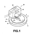
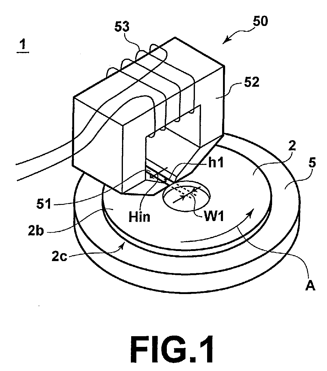
- the slave medium 2 is first applied with an initial DC magnetic field Hin by an initial magnetization system 1 shown in Figure 1 and the magnetic layer 2c and/or 2b of the slave medium 2 is initially magnetized in one direction of recording tracks.
- the initial magnetization system 1 shown in Figure 1 comprises a support table 5 which supports the slave medium 2 from the lower side 2c thereof, an electromagnet unit 50 held in the vicinity of the upper side 2b of the slave medium 2, and a rotating means (not shown) which rotates the support table 5 relatively to the electromagnet unit 50 in the direction of arrow A.
- the slave medium 2 is directly opposed to the magnetic poles of the electromagnet unit 50, and accordingly, the magnetic field generated by the electromagnet unit 50 is directly applied to the slave medium 2.
- the electromagnet unit 50 comprises a core 52 having a gap 51 which radially extends at least from an innermost track to an outermost track of the slave medium 2 and a winding 53 wound around the core 52.
- the electromagnet unit 50 generates an initial DC magnetic field Hin across the gap 51 in parallel to the direction of the recording tracks. Accordingly, by rotating the slave medium 2 once or more relatively to the initial DC magnetic field Hin, the initial DC magnetic field Hin parallel to the concentric recording tracks can be applied to over the entire recording track area.
- the width w1 of the gap 51 is set to be not larger than half of the radius of the innermost recording track and the distance h1 between the gap 51 and the upper surface of the slave medium is set to be not larger than 5mm (preferably 3mm) so that the initial DC magnetic field applied to the slave medium is not weaker than twice the coercive force of the magnetic layer of the slave medium 1 on both the sides of the slave medium 2.
- the width w1 of the gap 51 is set to be not larger than 10mm (preferably not larger than 5mm).
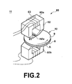
- the slave medium 2 together with the lower and upper master information carriers 3 and 4 held in close contact with the lower and upper side of the slave medium 2 is applied with a transfer magnetic field Hdu ( Figure2 2) by a transfer magnetic field application system 11 shown in Figure 2.
- the transfer magnetic field application system 11 comprises a holder 10 which holds the slave medium 2 and the master information carriers 3 and 4 in close contact with each other covering the upper and lower sides of the slave medium/master information carrier assembly, a magnetic field generator 60 having upper and lower electromagnet units 60a and 60b respectively opposed to the upper and lower sides 2b and 2c of the slave medium 2 and a rotating means (not shown) which rotates the holder 10 in the direction of arrow A relatively to the magnetic field generator 60. That is, in this transfer magnetic field application system 11, the slave medium 2, and the master information carriers 3 and 4 are accommodated in the holder 10, and the transfer magnetic field Hdu is applied to the slave medium 2, and the master information carriers 3 and 4 through the holder 10.
- Each of the upper and lower electromagnet units 60a and 60b of the magnetic field generator 60 comprises a core 62 having a gap 61 which radially extends at least from an innermost track to an outermost track of the slave medium 2 and a winding 63 wound around the core 62, and the upper and lower electromagnet units 60a and 60b generate magnetic fields parallel to the direction of the tracks in the same directions on opposite sides of the slave medium 2. It is not necessary to provide an electromagnet on each side of the slave medium but an electromagnet may be provided only on one side of the slave medium 2.
- the intensity of the transfer magnetic field is set to be not lower than about 0.6 times the coercive force Hc of the magnetic layer of the slave medium and not higher than about 1.3 times the coercive force of the magnetic layer of the slave medium (preferably 0.8Hc to 1.2Hc and more preferably 1Hc to 1.1Hc) on both the sides of the slave medium 2.
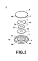
- Figure 3 is an exploded perspective view of the holder 10.
- the holder 10 comprises a lower holder member 8 having a lower correcting member 6 which holds the lower master information carrier 3, for transferring the information to the lower magnetic layer (the magnetic layer on the lower side 2c) of the slave medium 2, under suction force and forces it flat and an upper holder member 9 having an upper correcting member 7 (the same as the lower correcting member 6 in structure) which holds the upper master information carrier 4, for transferring the information to the upper magnetic layer (the magnetic layer on the upper side 2b) of the slave medium 2, under suction force and forces it flat.
- a lower holder member 8 having a lower correcting member 6 which holds the lower master information carrier 3, for transferring the information to the lower magnetic layer (the magnetic layer on the lower side 2c) of the slave medium 2, under suction force and forces it flat
- an upper holder member 9 having an upper correcting member 7 (the same as the lower correcting member 6 in structure) which holds the upper master information carrier 4, for transferring the information to the upper magnetic layer (the magnetic layer on the upper side 2b) of the slave medium 2,
- the upper and lower holder members 9 and 8 presses the upper and lower master information carriers 4 and 3 respectively against the upper and lower magnetic layers of the slave medium 2 with the centers of the upper and lower master information carriers 4 and 3 and the slave medium 2 aligned with each other, thereby holding the upper and lower master information carriers 4 and 3 and the slave medium 2 in close contact with each other.
- the lower and upper master information carriers 3 and 4 are respectively held under suction by lower and upper holder members 8 and 9 on the side opposite to the magnetic layer 3b and 4b carrying thereon the information to be transferred.
- small through holes extending from one side of the master information carrier to the other side may be formed in the master information carrier so that air trapped between the slave medium 2 and the master information carrier is purged therethrough at portions where the through holes do not interfere with the irregularity pattern representing the information to be transferred and do not communicate with suction holes (to be described later) of the correcting members 6 and 7.
- the lower correcting member 6 is like a disc in shape and is sized according to the size of the master information carrier 3.
- the surface of the lower correcting member 6 which is brought into contact with the master information carrier 3 is formed into a suction face 6a whose surface is about 0.01 to 0.1 ⁇ m in centerline mean surface roughness Ra.
- About 25 to 100 suction holes 6b not larger than about 2mm in diameter uniformly open is the suction face 6a.
- each of the suction holes 6b is connected to a vacuum pump through a vacuum passage which is led outside the lower holder member 8 through the lower correcting member 6.
- the back side (opposite to the magnetic layer) of the lower master information carrier 3 is forced flat along the suction face 6a under the suction force applied thereto through the suction holes 6b and thus the flatness of the lower master information carrier 3 is corrected.
- the upper correcting member 7 is the same as the lower correcting member 6 in structure, and will not be described here.
- the lower and upper holder member 8 and 9 are like a disc in shape and one or both of them is movable in the axial direction toward and away from each other.
- the lower and upper holder member 8 and 9 are opened and closed by an opening/closing mechanism (a pressing mechanism, a fastener mechanism or the like) not shown, and pressed against each other at a predetermined pressure when closed.
- the lower and upper holder member 8 and 9 are provided with flanges 8a and 9a on their outer peripheries which are brought into abutment against each other to close its inside in an air-tight fashion when the lower and upper holder member 8 and 9 are closed.
- a locator pin 8 which engages with the central opening of the slave medium 2 to locate the slave medium 2 is erected at the center of the lower holder member 8.
- the slave medium 2 is first placed on the support table 5 of the initial magnetization system 1 and an initial DC magnetic field Hin is generated across the gap 51 of the electromagnet unit 50.
- the magnetic field Hin is parallel to a tangent of the recording tracks, and the initial DC magnetic field is applied to over the entire area of the recording tracks by rotating the support table 5 (or the slave medium 2) relatively to the magnetic field once or more in the direction of arrow A by rotating means (not shown) .
- the intensity of the magnetic field Hin on the upper and lower sides 2b and 2c of the slave medium 2 it is necessary for the intensity of the magnetic field Hin on the upper and lower sides 2b and 2c of the slave medium 2 to be not weaker than the coercive force Hc of the slave medium 2.
- the strength of the magnetic field Hin on the lower side of the slave medium 2 is insufficient, it is necessary to turn over the slave medium 2 and to initially magnetize the magnetic layers on the opposite sides of the slave medium 2 in sequence.
- the master information carriers 3 and 4 and the slave medium 2 are set in the holder 10 with the lower master information carrier 3 and the upper master information carrier 4 respectively in close contact with the lower and upper magnetic layers of the slave medium 2 and the holder 10 is set to the transfer magnetic field application system 11.
- Each of the electromagnet units 60a and 60b opposed to the upper and lower surfaces of the holder 10 generates a transfer magnetic field Hdu in a direction opposite to the initial DC magnetic field.
- the transfer magnetic field Hdu is applied to over the entire area of the recording tracks by rotating the holder 10 relatively to the magnetic field once or more in the direction of arrow A, whereby the information represented by the irregularity patterns on the master information carriers 3 and 4 are magnetically transferred to the slave medium 2.
- An initial DC magnetic field Hin is applied to the slave medium 2 to magnetize the magnetic layers 2b and 2c of the slave medium 2 in a direction parallel to the recording tracks as shown in Figure 4A.
- the magnetic layer 3b of the lower master information carrier 3 and the magnetic layer 4b of the upper master information carrier 4 are brought into close contact with the lower and upper magnetic layers of the slave medium 2 by the holder 10.
- the holder 10 together with the slave medium 2 and the master information carriers 3 and 4 in close contact with opposite sides of the slave medium 2 is positioned in place between the upper and lower electromagnet units 60a and 60b of the transfer magnetic field application system 11 each generating a transfer magnetic field Hdu in a direction opposite to the initial DC magnetic field as shown in Figure 4B, thereby effecting magnetic transfer.
- the information represented by the irregularity pattern on each of the upper and lower master information carriers 3 and 4 is recorded on each of the magnetic layers 2b and 2c of the slave medium 2 as a magnetization pattern as shown in Figure 4C.
- the information can be magnetically transferred to the slave medium 2 by reversing the directions of the initial DC magnetic field Hin and the transfer magnetic field Hdu.
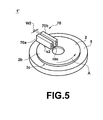
- FIG. 5 is a fragmentary perspective view showing an initial magnetization system 1' employed in a magnetic transfer apparatus for carrying out a method of magnetic transfer in accordance with a second embodiment of the present invention.
- the initial magnetization system 1' shown in Figure 5 differs from that 1 shown in Figure 1 in that a pair of permanent magnets 70a and 70b is employed as a magnetic field generator in place of an electromagnet unit 50.
- the initial magnetization system 1' has a magnetic field generator 70 comprising a pair of permanent magnets 70a and 70b which are magnetized in a direction substantially perpendicular to the upper side 2b of the slave medium 2 and radially extend from an innermost track to an outermost track of the slave medium 2 so that opposite poles of the respective permanent magnets 70a and 70b are opposed to the surface of the slave medium 2. Also, in this initial magnetization system 1', the permanent magnets 70a and 70b are directly opposed to the slave medium 2 and the magnetic field generated between the permanent magnets 70a and 70b is directly applied to the slave medium 2.
- the permanent magnets 70a and 70b generates an initial DC magnetic field Hin in parallel to the direction of the recording tracks. Accordingly, by rotating the slave medium 2 once or more relatively to the permanent magnets 70a and 70b, the initial DC magnetic field Hin can be applied to over the entire area of the slave medium 2.
- the intensity of the initial DC magnetic field Hin applied to the slave medium 2 is set to be not weaker than twice the coercive force Hc of the magnetic layer of the slave medium 2.
- a third permanent magnet 71 magnetized in a direction perpendicular to the direction of magnetization of the permanent magnets 70a and 70b may be inserted between the permanent magnets 70a and 70b so that the third permanent magnet 71 generates a magnetic field directed in the same direction as the magnetic field generated by the permanent magnets 70a and 70b, as in a magnetic field generator 70' shown in Figure 6.
- the magnetic field generated by the third permanent magnet 71 enhances the magnetic field generated by the permanent magnets 70a and 70b.
- the slave medium (or the holder) is rotated relatively to the magnetic field generator to apply the magnetic field to over the entire area of the slave medium 2, it is possible to rotate the latter relatively to the former.
- the surface of the slave medium (or the slave medium/master information carrier assembly) is held horizontal but the surface may be held vertical with the magnetic field generator opposed to the surface.
Landscapes
- Recording Or Reproducing By Magnetic Means (AREA)
- Magnetic Record Carriers (AREA)
- Manufacturing Of Magnetic Record Carriers (AREA)
Abstract
Description
applying an initial DC magnetic field to the slave medium by a magnetic field generator to initially magnetize the magnetic layer of the slave medium in one direction of recording tracks and
applying a transfer magnetic field to the slave medium and the master information carrier by a magnetic field generator in the direction opposite to the direction of the initial-magnetization with the initially-magnetized magnetic layer of the slave medium held in close contact with the magnetic layer on the master information carrier, wherein the improvement comprises that
the initial DC magnetic field is applied to the slave medium with the slave medium supported from one side thereof so that the other side of the slave medium is directly opposed to the magnetic field generator, and
the transfer magnetic field is applied to the slave medium and the master information carrier held in close contact with each other so that the initially-magnetized magnetic layer of the slave medium held in close contact with the magnetic layer on the master information carrier by a holder, which covers both the sides of the slave medium/master information carrier assembly, with the magnetic field generator positioned to oppose both the sides or one side of the slave medium/master information carrier assembly so that the magnetic field generated by the magnetic field generator is applied to the slave medium and the master information carrier through the holder.
Claims (7)
- A method of magnetic transfer for magnetically transferring information represented by a pattern of a magnetic layer formed on a master information carrier to a magnetic layer of a slave medium comprising the steps of
applying an initial DC magnetic field to the slave medium by a magnetic field generator to initially magnetize the magnetic layer of the slave medium in one direction of recording tracks and
applying a transfer magnetic field to the slave medium and the master information carrier by a magnetic field generator in the direction opposite to the direction of the initial-magnetization with the initially-magnetized magnetic layer of the slave medium held in close contact with the magnetic layer on the master information carrier, wherein the improvement comprises that
the initial DC magnetic field is applied to the slave medium with the slave medium supported from one side thereof so that the other side of the slave medium is directly opposed to the magnetic field generator, and
the transfer magnetic field is applied to the slave medium and the master information carrier held in close contact with each other so that the initially-magnetized magnetic layer of the slave medium held in close contact with the magnetic layer on the master information carrier by a holder, which covers both the sides of the slave medium/master information carrier assembly, with the magnetic field generator positioned to oppose both the sides or one side of the slave medium/master information carrier assembly so that the magnetic field generated by the magnetic field generator is applied to the slave medium and the master information carrier through the holder. - A method of magnetic transfer as defined in Claim 1 in which the intensity of the initial DC magnetic field is set to be not lower than the coercive force of the magnetic layer of the slave medium.
- A method of magnetic transfer as defined in Claim 2 in which the intensity of the initial DC magnetic field is set to be not lower than 1.2 times the coercive force of the magnetic layer of the slave medium.
- A method of magnetic transfer as defined in Claim 3 in which the intensity of the initial DC magnetic field is set to be not lower than twice the coercive force of the magnetic layer of the slave medium.
- A method of magnetic transfer as defined in any one of Claims 1 to 4 in which the intensity of the transfer magnetic field is set to be not lower than about 0.6 times the coercive force of the magnetic layer of the slave medium and not higher than about 1.3 times the coercive force of the magnetic layer of the slave medium.
- A method of magnetic transfer as defined in any one of Claims 1 to 5 in which the magnetic field generator comprises an electromagnet unit.
- A method of magnetic transfer as defined in any one of Claims 1 to 5 in which the magnetic field generator comprises a permanent magnet unit.
Applications Claiming Priority (2)
| Application Number | Priority Date | Filing Date | Title |
|---|---|---|---|
| JP2002048118A JP2003248922A (en) | 2002-02-25 | 2002-02-25 | Magnetic transfer method |
| JP2002048118 | 2002-02-25 |
Publications (2)
| Publication Number | Publication Date |
|---|---|
| EP1339046A2 true EP1339046A2 (en) | 2003-08-27 |
| EP1339046A3 EP1339046A3 (en) | 2008-05-28 |
Family
ID=27655435
Family Applications (1)
| Application Number | Title | Priority Date | Filing Date |
|---|---|---|---|
| EP03004211A Withdrawn EP1339046A3 (en) | 2002-02-25 | 2003-02-25 | Method of magnetic transfer |
Country Status (7)
| Country | Link |
|---|---|
| US (1) | US6972915B2 (en) |
| EP (1) | EP1339046A3 (en) |
| JP (1) | JP2003248922A (en) |
| KR (1) | KR100585826B1 (en) |
| CN (1) | CN1260710C (en) |
| MY (1) | MY134739A (en) |
| SG (1) | SG108904A1 (en) |
Families Citing this family (2)
| Publication number | Priority date | Publication date | Assignee | Title |
|---|---|---|---|---|
| JP4076056B2 (en) * | 2001-05-21 | 2008-04-16 | 富士フイルム株式会社 | Magnetic transfer method |
| JP4339865B2 (en) * | 2006-03-17 | 2009-10-07 | 富士通株式会社 | Manufacturing method of magnetic disk |
Family Cites Families (15)
| Publication number | Priority date | Publication date | Assignee | Title |
|---|---|---|---|---|
| JPS63183623A (en) | 1987-01-23 | 1988-07-29 | Sony Corp | Method for contact magnetic field transfer to flexible disk |
| US5121258A (en) | 1991-08-12 | 1992-06-09 | Eastman Kodak Company | Apparatus for anhysteretic duplication of a flexible magnetic disk |
| TW342495B (en) * | 1996-07-22 | 1998-10-11 | Matsushita Electric Industrial Co Ltd | Master information carrier, method of producing the same, and method for recording master information signal on magnetic recording medium |
| JP3361740B2 (en) * | 1998-03-23 | 2003-01-07 | 松下電器産業株式会社 | Master information magnetic recording device and method of manufacturing magnetic recording medium |
| US6433944B1 (en) * | 1998-09-25 | 2002-08-13 | Fuji Photo Film Co., Ltd. | Master carrier for magnetic transfer and method for transfer |
| JP2001014667A (en) | 1999-04-26 | 2001-01-19 | Fuji Photo Film Co Ltd | Magnetic transferring method and magnetic transferring device |
| JP2001143258A (en) | 1999-11-10 | 2001-05-25 | Fuji Photo Film Co Ltd | Magnetic transfer method |
| SG92760A1 (en) * | 2000-03-29 | 2002-11-19 | Fuji Photo Film Co Ltd | Magnetic transfer method and system |
| KR20020035776A (en) * | 2000-11-07 | 2002-05-15 | 무네유키 가코우 | Method and apparatus for magnetic transfer and magnetic recording medium |
| US6906875B2 (en) * | 2001-05-15 | 2005-06-14 | Fuji Photo Film Co., Ltd. | Magnetic transfer device |
| US20020187295A1 (en) * | 2001-05-15 | 2002-12-12 | Fuji Photo Film Co., Ltd. | Magnetic transfer master medium |
| CN1253857C (en) * | 2001-06-21 | 2006-04-26 | 富士胶片株式会社 | magnetic replication device |
| CN1260709C (en) * | 2002-02-12 | 2006-06-21 | 富士胶片株式会社 | magnetic replication method |
| JP2003303413A (en) * | 2002-04-04 | 2003-10-24 | Fuji Photo Film Co Ltd | Magnetic transfer device |
| EP1376548A3 (en) * | 2002-06-25 | 2008-07-30 | FUJIFILM Corporation | Magnetic transfer system |
-
2002
- 2002-02-25 JP JP2002048118A patent/JP2003248922A/en active Pending
-
2003
- 2003-02-24 KR KR1020030011349A patent/KR100585826B1/en not_active Expired - Fee Related
- 2003-02-24 SG SG200300772A patent/SG108904A1/en unknown
- 2003-02-24 MY MYPI20030628A patent/MY134739A/en unknown
- 2003-02-24 US US10/370,477 patent/US6972915B2/en not_active Expired - Fee Related
- 2003-02-25 CN CNB03106440XA patent/CN1260710C/en not_active Expired - Fee Related
- 2003-02-25 EP EP03004211A patent/EP1339046A3/en not_active Withdrawn
Also Published As
| Publication number | Publication date |
|---|---|
| US6972915B2 (en) | 2005-12-06 |
| SG108904A1 (en) | 2005-02-28 |
| CN1441408A (en) | 2003-09-10 |
| EP1339046A3 (en) | 2008-05-28 |
| JP2003248922A (en) | 2003-09-05 |
| US20030161060A1 (en) | 2003-08-28 |
| KR20030070550A (en) | 2003-08-30 |
| KR100585826B1 (en) | 2006-06-07 |
| CN1260710C (en) | 2006-06-21 |
| MY134739A (en) | 2007-12-31 |
Similar Documents
| Publication | Publication Date | Title |
|---|---|---|
| US6954317B2 (en) | Magnetic transfer method and apparatus | |
| US6804070B2 (en) | Magnetic transfer apparatus | |
| US6867935B2 (en) | Magnetic transfer apparatus | |
| US7079335B2 (en) | Magnetic transfer method and apparatus | |
| US6972915B2 (en) | Method of magnetic transfer using a side-supported slave medium directly opposed to the magnetic field generator | |
| US7038868B2 (en) | Method of magnetic transfer and stopping slave medium rotation | |
| EP1930885A1 (en) | Master information carrier for magnetic transfer, magnetic transfer method, and magnetic recording medium | |
| US6909634B2 (en) | Magnetic transfer method and magnetic transfer device | |
| US20040233559A1 (en) | Master carrier for magnetic transfer and magnetic transfer method | |
| EP1258867A2 (en) | Magnetic transfer method and apparatus | |
| JP3731813B2 (en) | Magnetic transfer device | |
| JP3999709B2 (en) | Master carrier for magnetic transfer and magnetic transfer method | |
| JP4044065B2 (en) | Master carrier for magnetic transfer, magnetic transfer method | |
| US20080192587A1 (en) | Transfer apparatus, transfer method, recording medium, and magnetic recording apparatus | |
| US20060114586A1 (en) | Magnetic transfer apparatus | |
| JP2003228829A (en) | Magnetic transfer method | |
| KR20020064203A (en) | Method and apparatus for magnetic transfer | |
| JP2002304723A (en) | Magnetic transfer method | |
| JP2006236466A (en) | Master carrier for magnetic transfer | |
| JP2006252609A (en) | Method for adsorbing and holding master disk and magnetic transfer device |
Legal Events
| Date | Code | Title | Description |
|---|---|---|---|
| PUAI | Public reference made under article 153(3) epc to a published international application that has entered the european phase |
Free format text: ORIGINAL CODE: 0009012 |
|
| AK | Designated contracting states |
Designated state(s): AT BE BG CH CY CZ DE DK EE ES FI FR GB GR HU IE IT LI LU MC NL PT SE SI SK TR |
|
| AX | Request for extension of the european patent |
Extension state: AL LT LV MK RO |
|
| RAP1 | Party data changed (applicant data changed or rights of an application transferred) |
Owner name: FUJIFILM CORPORATION |
|
| PUAL | Search report despatched |
Free format text: ORIGINAL CODE: 0009013 |
|
| AK | Designated contracting states |
Kind code of ref document: A3 Designated state(s): AT BE BG CH CY CZ DE DK EE ES FI FR GB GR HU IE IT LI LU MC NL PT SE SI SK TR |
|
| AX | Request for extension of the european patent |
Extension state: AL LT LV MK RO |
|
| 17P | Request for examination filed |
Effective date: 20080918 |
|
| 17Q | First examination report despatched |
Effective date: 20081110 |
|
| AKX | Designation fees paid |
Designated state(s): DE FR GB |
|
| STAA | Information on the status of an ep patent application or granted ep patent |
Free format text: STATUS: THE APPLICATION IS DEEMED TO BE WITHDRAWN |
|
| 18D | Application deemed to be withdrawn |
Effective date: 20090321 |