EP1338937A1 - Servo control method - Google Patents
Servo control method Download PDFInfo
- Publication number
- EP1338937A1 EP1338937A1 EP01963570A EP01963570A EP1338937A1 EP 1338937 A1 EP1338937 A1 EP 1338937A1 EP 01963570 A EP01963570 A EP 01963570A EP 01963570 A EP01963570 A EP 01963570A EP 1338937 A1 EP1338937 A1 EP 1338937A1
- Authority
- EP
- European Patent Office
- Prior art keywords
- motor
- references
- speed
- feed
- control method
- Prior art date
- Legal status (The legal status is an assumption and is not a legal conclusion. Google has not performed a legal analysis and makes no representation as to the accuracy of the status listed.)
- Withdrawn
Links
Images

Classifications
-
- G—PHYSICS
- G05—CONTROLLING; REGULATING
- G05B—CONTROL OR REGULATING SYSTEMS IN GENERAL; FUNCTIONAL ELEMENTS OF SUCH SYSTEMS; MONITORING OR TESTING ARRANGEMENTS FOR SUCH SYSTEMS OR ELEMENTS
- G05B19/00—Program-control systems
- G05B19/02—Program-control systems electric
- G05B19/18—Numerical control [NC], i.e. automatically operating machines, in particular machine tools, e.g. in a manufacturing environment, so as to execute positioning, movement or co-ordinated operations by means of program data in numerical form
- G05B19/19—Numerical control [NC], i.e. automatically operating machines, in particular machine tools, e.g. in a manufacturing environment, so as to execute positioning, movement or co-ordinated operations by means of program data in numerical form characterised by positioning or contouring control systems, e.g. to control position from one programmed point to another or to control movement along a programmed continuous path
-
- G—PHYSICS
- G05—CONTROLLING; REGULATING
- G05D—SYSTEMS FOR CONTROLLING OR REGULATING NON-ELECTRIC VARIABLES
- G05D3/00—Control of position or direction
- G05D3/12—Control of position or direction using feedback
-
- G—PHYSICS
- G05—CONTROLLING; REGULATING
- G05B—CONTROL OR REGULATING SYSTEMS IN GENERAL; FUNCTIONAL ELEMENTS OF SUCH SYSTEMS; MONITORING OR TESTING ARRANGEMENTS FOR SUCH SYSTEMS OR ELEMENTS
- G05B2219/00—Program-control systems
- G05B2219/30—Nc systems
- G05B2219/41—Servomotor, servo controller till figures
- G05B2219/41428—Feedforward of position and speed
Definitions
- the present invention relates to a method for controlling a servomotor that drives a feed shaft of a machine tool and a robot arm, etc., and in particular, a method for carrying out feed-forward control in order to improve the follow-up ability to references.
- feed-forward control has been frequently employed as a method for improving the follow-up ability to references.
- a value obtained by differentiating a position reference is used as a speed feed-forward reference value, and a value obtained by differentiating the same again is used as a torque feed-forward reference value.
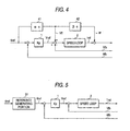
- Fig. 4 is a block diagram showing the construction of a prior art system.
- the method is such that a value obtained by multiplying a deviation between position reference ⁇ ref and real position ⁇ fb by position loop gain Kp at position "1" is made into speed reference Vref, next, a value obtained by multiplying a value, which is obtained by differentiating the position reference value ⁇ ref at a differentiator 41, by coefficient ⁇ is made into speed feed-forward reference Vff, and is added to the speed reference Vref.
- FIG. 5 discloses a method for improving a follow-up ability to references and achieving complete follow-up, wherein a transfer function including a control system and a mechanics system is inversely solved in the reference generating portion 51, a position reference is prepared, in which a transfer function from a position reference to a load position is made into 1.
- Reference symbols shown in Fig. 5 are the same as those in Fig. 4.
- the present invention provides a servo control method using feed-forward, in which the position of a load and the position of a motor are expressed by respective functions capable of higher order differentiation, the respective functions capable of higher order differentiation being determined on the basis of operating conditions and mechanical parameters, the position, speed and torque references of the motor are calculated from functions capable of a determined higher order differentiation, and the obtained motor position and speed, and the above-described torque references are made into feed-forward references.
- the present invention provides a servo control method using feed-forward, in which the position of a load and the position of a motor are expressed by respective functions capable of higher order differentiation, the respective functions capable of higher order differentiation being determined on the basis of the operating conditions and mechanical parameters, torque references of the motor are calculated from functions capable of the determined higher order differentiation, the calculated torque references are inputted into a mechanical model, and the obtained motor position, speed, and the above-described torque references are made into feed-forward references.
- functions capable of higher order differentiation may be the 15th order polynomial equation.
- the above-described operating conditions may be a moving distance and moving time.
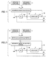
- Fig. 1 is a block diagram showing an embodiment of the invention.
- reference number 1 denotes a position loop proportional gain Kp
- 2 denotes a speed loop
- 3 denotes an reference generating portion for calculating a motor position, speed, and torque reference.
- Prescribed operating conditions 4 are stored in a memory.
- Reference number 5 denotes amechanical parameter which is stored in a memory.
- Proportional integration control is carried out in the speed loop 2. Also, a moving distance dist and moving time te are inputted and stored as the operating conditions 4 as set forth in Claim 4. Motor inertia J1, load inertia J2, spring constant Kc, and dumping coefficient DL are inputted and stored as the mechanical parameters 5.
- motor position reference ⁇ ref Using the four operating conditions and five mechanical parameters, which are stored in the memory, motor position reference ⁇ ref, motor speed reference Vff, and motor torque reference value Tff are calculated by the reference generating portion 3 and are made into control inputs.
- references are generated not by a transfer function including the control system but by only the dynamic equation of the mechanics system, it is not necessary to change any references without being influenced at all with respect to a change in the control gain.
- the torque reference value Tref(t) is led out by the sequence described in Embodiment 1.
- amechanical model is held in advance in the controller, and the torque reference led out as described above is inputted into the mechanical model, and the motor position and motor speed, which are calculated in the mechanical model, may be made into the feed-forward reference values.
- it is sufficient that only the torque reference is inputted into the control calculation portion, wherein effects similar to those in Embodiment 1 can be brought about.
- the load position and motor position are expressed by a higher-order differentiable polynomial equation, and coefficients of the polynomial equation are determined according to the boundary conditions obtained from the operating conditions (moving distance and moving time) and a mechanical dynamic equation.
- the motor position reference, motor speed reference, and motor torque reference are calculated, and these are used as feed-forward reference values, whereby such an effect can be brought about, by which a flexible structure can be caused to completely follow up with references.
- the same reference may be used, wherein such an effect can be brought about, by which troublesome re-calculations, etc., are not required even in the case where the feed-forward references are calculated in advance by an off-line process.
Landscapes
- Engineering & Computer Science (AREA)
- Physics & Mathematics (AREA)
- General Physics & Mathematics (AREA)
- Automation & Control Theory (AREA)
- Human Computer Interaction (AREA)
- Manufacturing & Machinery (AREA)
- Control Of Electric Motors In General (AREA)
- Control Of Position Or Direction (AREA)
- Manipulator (AREA)
- Feedback Control In General (AREA)
Abstract
Description
- Operating conditions: dist, te
- Mechanical parameters: J1, J2, Kc, DL
- 4
- Operating conditions
- 5
- Mechanical parameters
- 3
- Reference generating portion
- 2
- Speed loop
- 4
- Operating conditions
- 5
- Mechanical parameters
- 3
- Reference generating portion
- 6
- Mechanical model calculation portion
- 2
- Speed loop
- 2
- Speed loop
- 51
- Reference generating portion
- 2
- Speed loop
Claims (5)
- A servo control method using feed-forward, comprising: the steps of expressing a load position and a motor position in terms of a higher-order differentiable function; determining said higher-order differentiable function on the basis of operating conditions and mechanical parameters; calculating the position, speed and torque reference of said motor on the basis of said determined higher-order differentiable function; and making said calculated motor position, speed, and torque references into feed-forward references.
- A servo control method using feed-forward, comprising: the steps of expressing a load position and a motor position in terms of a higher-order differentiable function; determining said higher-order differentiable function on the basis of operating conditions and mechanical parameters; calculating torque references of said motor on the basis of said determined higher-order differentiable function; inputting said calculated torque references into a mechanical model; and making said obtained motor position, speed, and torque references into feed-forward references.
- The servo control method as set forth in Claim 1 or 2, wherein said higher-order differentiable function is a 15th order polynomial equation.
- The servo control method as set forth in Claim 1 or 2, wherein said operating conditions are a moving distance and moving time.
- The servo control method as set forth in Claim 1 or 2, wherein a dynamic equation of the mechanics system is used, which is controlled when said higher-order differentiable function is determined.
Applications Claiming Priority (3)
| Application Number | Priority Date | Filing Date | Title |
|---|---|---|---|
| JP2000284444A JP2002091570A (en) | 2000-09-20 | 2000-09-20 | Servo control method |
| JP2000284444 | 2000-09-20 | ||
| PCT/JP2001/007851 WO2002025390A1 (en) | 2000-09-20 | 2001-09-10 | Servo control method |
Publications (2)
| Publication Number | Publication Date |
|---|---|
| EP1338937A1 true EP1338937A1 (en) | 2003-08-27 |
| EP1338937A4 EP1338937A4 (en) | 2004-03-17 |
Family
ID=18768651
Family Applications (1)
| Application Number | Title | Priority Date | Filing Date |
|---|---|---|---|
| EP01963570A Withdrawn EP1338937A4 (en) | 2000-09-20 | 2001-09-10 | SERVO CONTROL PROCESS |
Country Status (7)
| Country | Link |
|---|---|
| US (1) | US20030173928A1 (en) |
| EP (1) | EP1338937A4 (en) |
| JP (1) | JP2002091570A (en) |
| KR (1) | KR100842978B1 (en) |
| CN (1) | CN100343767C (en) |
| TW (1) | TW525045B (en) |
| WO (1) | WO2002025390A1 (en) |
Cited By (1)
| Publication number | Priority date | Publication date | Assignee | Title |
|---|---|---|---|---|
| EP1785792A1 (en) | 2005-11-11 | 2007-05-16 | C.C.M. Beheer B.V. | Method and system for control of a compliant system |
Families Citing this family (11)
| Publication number | Priority date | Publication date | Assignee | Title |
|---|---|---|---|---|
| JP4541218B2 (en) | 2005-04-08 | 2010-09-08 | 三菱電機株式会社 | Command generator |
| JP5011700B2 (en) * | 2005-09-23 | 2012-08-29 | 日本電産株式会社 | Power steering electric drive |
| JP4673326B2 (en) * | 2007-01-11 | 2011-04-20 | オークマ株式会社 | Rotary shaft position control device |
| JP4807600B2 (en) * | 2009-08-18 | 2011-11-02 | 村田機械株式会社 | Mobile system |
| KR101793685B1 (en) | 2011-09-19 | 2017-11-06 | 한화지상방산 주식회사 | Control system for rotating shaft |
| CN104348393A (en) * | 2013-07-23 | 2015-02-11 | 广东美的制冷设备有限公司 | Air conditioner, variable-frequency speed regulation system and control method thereof |
| JP6106582B2 (en) * | 2013-12-09 | 2017-04-05 | 山洋電気株式会社 | Motor control device |
| KR102698952B1 (en) * | 2020-02-13 | 2024-08-23 | 엘에스일렉트릭(주) | Position controlling apparatus for motor |
| KR102698936B1 (en) * | 2020-02-13 | 2024-08-23 | 엘에스일렉트릭(주) | Position controlling apparatus for motor |
| JP7508920B2 (en) * | 2020-07-22 | 2024-07-02 | 富士電機株式会社 | Control device and design method |
| CN111872942B (en) * | 2020-08-07 | 2023-06-20 | 四川福莫斯工业技术有限公司 | A torque feed-forward method for multi-axis robots |
Family Cites Families (18)
| Publication number | Priority date | Publication date | Assignee | Title |
|---|---|---|---|---|
| JP2559279B2 (en) * | 1989-11-30 | 1996-12-04 | 三菱電機株式会社 | Servo motor superposition / synchronous operation error correction device |
| KR940003005B1 (en) * | 1991-01-26 | 1994-04-09 | 삼성전자 주식회사 | Arrangement for speed regulation of electric motor |
| JP2810246B2 (en) * | 1991-02-25 | 1998-10-15 | オークマ株式会社 | Drive control device |
| DE69223236T2 (en) * | 1991-09-09 | 1998-03-19 | Fanuc Ltd | METHOD FOR CONTROLLING A SERVO MOTOR WITH FORWARD CLUTCH |
| JP3084928B2 (en) * | 1992-05-29 | 2000-09-04 | 三菱電機株式会社 | Motor position control device |
| JPH06147468A (en) * | 1992-11-16 | 1994-05-27 | Sanden Corp | Method for controlling gasification type combustion device |
| JP3296527B2 (en) * | 1994-08-05 | 2002-07-02 | 株式会社安川電機 | Motor speed control device |
| CN1187887A (en) * | 1995-06-14 | 1998-07-15 | 霍尼韦尔公司 | Method of Adding Independent Feedforward Control to Multivariable Predictive Controller |
| JPH11265202A (en) * | 1998-01-14 | 1999-09-28 | Sony Corp | Control method and control device |
| JP3313643B2 (en) * | 1998-04-30 | 2002-08-12 | 東芝機械株式会社 | Servo control method in orbit machining with bite tool and servo controller for orbit machining |
| JP2000148210A (en) * | 1998-11-12 | 2000-05-26 | Toyota Central Res & Dev Lab Inc | Gain calculator |
| JP3621278B2 (en) * | 1998-12-10 | 2005-02-16 | 三菱電機株式会社 | Servo control device |
| US7433144B2 (en) * | 1999-03-04 | 2008-10-07 | Convolve, Inc. | Dynamic system control method |
| US6470225B1 (en) * | 1999-04-16 | 2002-10-22 | Siemens Energy & Automation, Inc. | Method and apparatus for automatically tuning feedforward parameters |
| US6961628B2 (en) * | 1999-04-16 | 2005-11-01 | Siemens Energy & Automation, Inc. | Method and apparatus for tuning compensation parameters |
| SE0001312D0 (en) * | 2000-04-10 | 2000-04-10 | Abb Ab | Industrial robot |
| US6677722B2 (en) * | 2001-04-19 | 2004-01-13 | Toshiba Kikai Kabushiki Kaisha | Servo control method |
| JP4875413B2 (en) * | 2006-06-22 | 2012-02-15 | グンゼ株式会社 | clothing |
-
2000
- 2000-09-20 JP JP2000284444A patent/JP2002091570A/en not_active Abandoned
-
2001
- 2001-09-10 WO PCT/JP2001/007851 patent/WO2002025390A1/en not_active Ceased
- 2001-09-10 US US10/380,827 patent/US20030173928A1/en not_active Abandoned
- 2001-09-10 CN CNB018158528A patent/CN100343767C/en not_active Expired - Fee Related
- 2001-09-10 KR KR1020037003929A patent/KR100842978B1/en not_active Expired - Fee Related
- 2001-09-10 EP EP01963570A patent/EP1338937A4/en not_active Withdrawn
- 2001-09-19 TW TW090123112A patent/TW525045B/en not_active IP Right Cessation
Cited By (1)
| Publication number | Priority date | Publication date | Assignee | Title |
|---|---|---|---|---|
| EP1785792A1 (en) | 2005-11-11 | 2007-05-16 | C.C.M. Beheer B.V. | Method and system for control of a compliant system |
Also Published As
| Publication number | Publication date |
|---|---|
| CN100343767C (en) | 2007-10-17 |
| EP1338937A4 (en) | 2004-03-17 |
| CN1633629A (en) | 2005-06-29 |
| TW525045B (en) | 2003-03-21 |
| KR100842978B1 (en) | 2008-07-01 |
| JP2002091570A (en) | 2002-03-29 |
| KR20030036802A (en) | 2003-05-09 |
| WO2002025390A1 (en) | 2002-03-28 |
| US20030173928A1 (en) | 2003-09-18 |
Similar Documents
| Publication | Publication Date | Title |
|---|---|---|
| US10481566B2 (en) | Machine learning device, servo control device, servo control system and machine learning method | |
| JP3506157B2 (en) | Motor position control device | |
| EP0417312A1 (en) | Feedforward control unit for servomotor | |
| CN108356823A (en) | Control system with learning control function and control method | |
| JPH04233001A (en) | Time-delay controlling method | |
| JP2017102617A (en) | Correction apparatus, correction apparatus control method, information processing program, and recording medium | |
| US6825631B1 (en) | Prediction controlling device | |
| US20030173928A1 (en) | Servo control method | |
| JP4697139B2 (en) | Servo control device | |
| US5986422A (en) | Control mode changing over method for servo control system | |
| CN114043999B (en) | A method and device for longitudinal control of a vehicle | |
| US5637969A (en) | Vibration control method | |
| CN110941242A (en) | Motor control device | |
| EP0510212B1 (en) | Method for controlling servomotor feedforward | |
| CN114063662B (en) | Control method and control device based on dynamic torque compensation | |
| CN110929874A (en) | Characteristic determination device, characteristic determination method, and characteristic determination program | |
| KR970002259B1 (en) | Servo motor control method | |
| JP3582541B2 (en) | Positioning control method by sliding mode control | |
| JPH0475113A (en) | Controller | |
| JPH10149210A (en) | Command creation method for positioning control system | |
| JP2003274684A (en) | Servo control device | |
| JPH06266425A (en) | Controller of robot | |
| CN118884820A (en) | A digital signal heterogeneous controller system for multi-axis motion systems | |
| JP3188396B2 (en) | Feed rate control method and apparatus in numerical control | |
| Soeterboek et al. | An application of a self-tuning controller on a robotic manipulator |
Legal Events
| Date | Code | Title | Description |
|---|---|---|---|
| PUAI | Public reference made under article 153(3) epc to a published international application that has entered the european phase |
Free format text: ORIGINAL CODE: 0009012 |
|
| 17P | Request for examination filed |
Effective date: 20030318 |
|
| AK | Designated contracting states |
Designated state(s): AT BE CH CY DE DK ES FI FR GB GR IE IT LI LU MC NL PT SE TR |
|
| AX | Request for extension of the european patent |
Extension state: AL LT LV MK RO SI |
|
| A4 | Supplementary search report drawn up and despatched |
Effective date: 20040130 |
|
| RIC1 | Information provided on ipc code assigned before grant |
Ipc: 7G 05B 19/19 B Ipc: 7G 05D 3/12 A |
|
| RBV | Designated contracting states (corrected) |
Designated state(s): DE GB |
|
| GRAP | Despatch of communication of intention to grant a patent |
Free format text: ORIGINAL CODE: EPIDOSNIGR1 |
|
| STAA | Information on the status of an ep patent application or granted ep patent |
Free format text: STATUS: THE APPLICATION IS DEEMED TO BE WITHDRAWN |
|
| 18D | Application deemed to be withdrawn |
Effective date: 20081018 |