EP1338930A1 - Electrophotographic image forming apparatus using non-volatile ink carrier liquid - Google Patents
Electrophotographic image forming apparatus using non-volatile ink carrier liquid Download PDFInfo
- Publication number
- EP1338930A1 EP1338930A1 EP02255992A EP02255992A EP1338930A1 EP 1338930 A1 EP1338930 A1 EP 1338930A1 EP 02255992 A EP02255992 A EP 02255992A EP 02255992 A EP02255992 A EP 02255992A EP 1338930 A1 EP1338930 A1 EP 1338930A1
- Authority
- EP
- European Patent Office
- Prior art keywords
- developing
- developing solution
- unit
- carrier
- image
- Prior art date
- Legal status (The legal status is an assumption and is not a legal conclusion. Google has not performed a legal analysis and makes no representation as to the accuracy of the status listed.)
- Granted
Links
Images


Classifications
-
- G—PHYSICS
- G03—PHOTOGRAPHY; CINEMATOGRAPHY; ANALOGOUS TECHNIQUES USING WAVES OTHER THAN OPTICAL WAVES; ELECTROGRAPHY; HOLOGRAPHY
- G03G—ELECTROGRAPHY; ELECTROPHOTOGRAPHY; MAGNETOGRAPHY
- G03G13/00—Electrographic processes using a charge pattern
- G03G13/06—Developing
- G03G13/10—Developing using a liquid developer, e.g. liquid suspension
-
- G—PHYSICS
- G03—PHOTOGRAPHY; CINEMATOGRAPHY; ANALOGOUS TECHNIQUES USING WAVES OTHER THAN OPTICAL WAVES; ELECTROGRAPHY; HOLOGRAPHY
- G03G—ELECTROGRAPHY; ELECTROPHOTOGRAPHY; MAGNETOGRAPHY
- G03G15/00—Apparatus for electrographic processes using a charge pattern
- G03G15/06—Apparatus for electrographic processes using a charge pattern for developing
-
- G—PHYSICS
- G03—PHOTOGRAPHY; CINEMATOGRAPHY; ANALOGOUS TECHNIQUES USING WAVES OTHER THAN OPTICAL WAVES; ELECTROGRAPHY; HOLOGRAPHY
- G03G—ELECTROGRAPHY; ELECTROPHOTOGRAPHY; MAGNETOGRAPHY
- G03G9/00—Developers
- G03G9/08—Developers with toner particles
- G03G9/12—Developers with toner particles in liquid developer mixtures
- G03G9/125—Developers with toner particles in liquid developer mixtures characterised by the liquid
Definitions
- the present invention relates to a liquid electrophotographic image forming apparatus, and more particularly, to a liquid electrophotographic image forming apparatus using a developing agent in which a non-volatile ink carrier is used as a solvent.
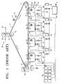
- FIG. 1 is a cross-sectional view of a conventional liquid electrophotographic image forming apparatus.
- the liquid electrophotographic image forming apparatus includes a photosensitive belt 14, a charger 15 for charging the photosensitive belt 14, laser scanning units (LSUs) 16 for projecting light onto the charged photosensitive belt 14 and forming a latent electrostatic image, developing units 30 for developing the latent electrostatic image, a dryer 18 for absorbing and vaporizing a liquid carrier on the photosensitive belt 14, and a transfer unit 20 for transferring the image onto a paper 23.
- LSUs laser scanning units
- the photosensitive belt 14 is circulated by a plurality of rollers including a driving roller 11 and passive rollers 12 and 13. Paper 23 is fed into the transfer unit 20 by rotation of a transfer roller 21 and a fixing roller 22, and the image is transferred onto the paper 23.
- the LSU 16 scans data related to colors, such as yellow (Y), cyan (C), magenta (M), and black (K), onto the photosensitive belt 14, and each developing unit 30 supplies a developing solution of corresponding colors onto the photosensitive belt 14.
- colors such as yellow (Y), cyan (C), magenta (M), and black (K)
- the developing unit 30 includes a developing solution supplier 32 for supplying a developing solution onto the photosensitive belt 14 and a developing container 31 for capturing the developing solution that drops from the photosensitive belt 14.
- the developing container 31 includes a developing roller 36, a brush roller 37 for removing the developing solution that is stained on the developing roller 36, a squeeze roller 34 for separating a liquid carrier that does not form images from the developing solution that is supplied onto the photosensitive belt 14, and a plate 35 for capturing the liquid carrier that is squeezed out of the squeeze roller 34 into the developing container 31.
- the developing unit 30 includes the developing roller 36 charged to a predetermined voltage, for maintaining a developing gap in the photosensitive belt 14 so that latent electrostatic images for each color such as Y, C, M, and K, are developed, an injector for supplying the developing solution to the developing gap, and the squeeze roller 34 that is placed to apply pressure onto the photosensitive belt 14.
- the developing solution comprises ink having a high concentration of a toner, which is transferred onto the paper 23 and forms an image, and a low concentration of a liquid carrier for transferring the toner to a region where the latent electrostatic image of the photosensitive belt 11 is formed.
- a liquid carrier used as a solvent and ink that is a developing material and has colors, such as Y, C, M, and K, are supplied from an ink cartridge 38 to the developing solution supplier 32.
- a developing solution having a proper concentration in which the liquid carrier is mixed with the ink, and a developing solution that is stored in the developing container 31 are supplied to the developing solution supplier 32, and the developing solution supplier 32 supplies the developing solution to the photosensitive belt 14.
- the ink having a concentration of 10-30% that is supplied from the ink cartridge 38 is diluted with a carrier having a low concentration and is supplied to the developing unit 30.
- the ink is supplied between the developing roller 36 and the photosensitive belt 14 using a developing supply unit 35.
- the developing solution having a low concentration forms a latent electrostatic image on the photosensitive belt 14, and then passes the squeeze roller 34, and thus, a surplus carrier is removed.
- a residual carrier is absorbed into the dryer 18 and is heated and vaporized, captured and compressed by a condenser, and then removed.
- the toner having a high concentration and forming an image on the photosensitive belt 14 is transferred to the transfer roller 21 by heat, pressure, or electrostatic force, and part of the residual carrier is vaporized by heat and pressure that is applied to the fixing roller 22 so that the image is retransferred onto the paper 23, and is thus printed out.
- a liquid ink carrier is used in the conventional image forming apparatus using a liquid developing agent, and thus, a high quality image can be acquired.
- the flash point of a carrier of a liquid developing solution is less than 80°C, and thus, when the liquid ink carrier is fixed at a temperature of more than 110°C and vaporized, the liquid ink carrier smells.
- a complex vapor capture system for supplying and capturing vapor of the vaporized carrier is required, and thus the volume of the image forming apparatus is increased and the structure of the image forming apparatus becomes complicated.
- An additional cooler is required also for the condensation of the captured carrier.
- the concentration of the liquid developing solution is 2-3% and is different from the concentration of 10-30% of the ink that is provided in the ink cartridge 38, and thus a complex ink supply system and a concentration controlling apparatus are required to prepare a developing solution having a concentration of 2-3% by mixing ink having a high concentration with a carrier. Also, a squeeze process is required to remove a surplus carrier remaining in a liquid developing agent having a low concentration.
- a liquid electrophotographic image forming apparatus comprising: a photosensitive body; a charge unit for increasing a potential of the photosensitive body to a charge potential; an exposure unit for projecting a beam onto the photosensitive body and forming a latent electrostatic image; a developing solution supply unit for supplying a developing solution to the photosensitive body, having a high concentration where a non-volatile carrier is used as a dispersion solvent; a developing unit to which the developing solution having a high concentration is supplied for forming a developing film having a high concentration and developing the latent electrostatic image; a transfer unit for contacting the photosensitive body and moving the developed image to a recording medium; and a fixing unit for fixing the transferred image in the recording medium at a temperature lower than the flash point of the carrier.
- the non-volatile carrier includes perfluocarbons (compound including fluorine (F) and carbon (C)), silicon oil, vegetable oil, and hydrocarbon, has relative permittivity and low surface tension, and has a flash point of more than 90°C.
- the developing solution has a high concentration of 2-40%, a glass transition temperature (Tg) of more than 30°C, and a melting point (Tm) that is not melted at a temperature 20°C more than the flash point of the carrier.
- Tg glass transition temperature
- Tm melting point
- the apparatus further includes a metering unit for forming an ink film having a high concentration.
- liquid ink where a non-volatile carrier is used as a dispersion solvent smell due to the vapor of the carrier during a printing step or from a printed matter can be prevented, fixing energy is reduced, and use of a developing solution having a high concentration is avoided, and a dryer or condenser for removing a carrier is not required. Also, a high quality image can be acquired without the contamination of a non-image portion during a contacting and developing step, and a squeeze process of removing a surplus carrier is not required.
- FIG. 2 is a schematic diagram of an image forming apparatus according to an embodiment of the present invention.
- the image forming apparatus 50 includes a plurality of photosensitive bodies 51 on which a latent electrostatic image for each color such as Y, C, M, and K, is formed, charge rollers 52 for increasing the surface potential of the photosensitive body 51 to charge potential, exposure units 55 for projecting light onto the charged photosensitive body 51 and forming a latent electrostatic image, developing units 53 for developing the latent electrostatic image, an intermediate transfer belt (ITB) 59 for contacting the photosensitive body 51 and moving the developed image, a transfer roller 56 for transferring the image that is moved from the ITB 59 onto a paper S, and a fixing unit 54 for fixing the transferred image.
- the ITB 59 and the transfer roller 56 constitute a transfer unit.
- the exposure unit 55 scans data related to colors, such as yellow (Y), cyan (C), magenta (M), and black (K), onto the photosensitive body 51 to decrease the exposure potential, thereby forming a latent electrostatic image for each color.
- Each developing unit 53 supplies the developing solution 68 for each color to the photosensitive body 51 to form a latent electrostatic image.
- a toner on the photosensitive body 51 is moved to the ITB 59 by an electrostatic force, and a toner for each color overlaps and is transferred when passing each developing unit 53.
- the transfer characteristics In a case where elastic rubber is used for the ITB 59, pressure during a transfer step is about 2 ⁇ 4kgf, and a transfer voltage is set to 400-1500V, the transfer characteristics of 90-99% can be achieved.
- the transfer characteristics depend on the remaining amount of a carrier in the previous step, and the most proper transfer characteristics can be achieved when the toner has a concentration of about 30-40%.
- the fixing unit 54 includes two fixing rollers and fixes the image on the paper S by passing the paper S onto which an image is transferred, through the two fixing rollers.
- the fixing rollers are heated at a temperature lower than the flash point of the carrier and pressure of about 10-30kgf is applied to the fixing rollers, the vaporization of the carrier can be minimized during a fixing step.
- a developing solution where a non-volatile carrier is used as a dispersion solvent, and the developing unit 53 for supplying the developing solution to the photosensitive body 51, will be described below with reference to Figure 3.
- the developing unit included in the image forming apparatus includes the developing unit 53 where the developing solution 68 is soaked, a depositing roller 67, which is soaked in the developing solution 68 in the developing unit 53, contacts the developing roller 63 or forms a developing gap in the developing roller 63 and supplies the developing solution 68, a developing roller 63 of which half is soaked in the developing solution 68 rotates in an arrow direction and retains the particles of the toner attached by the depositing roller 67, a metering blade 61 for applying predetermined pressure to the developing roller 63 and adjusting the thickness of the toner attached to the developing roller 63, and a cleaning roller 65, which contacts the developing roller 63, rotates in the same direction and cleans the undeveloped toner.
- the developing unit 53 included in the image forming apparatus includes an ink cartridge 57 in which ink 62 having a high concentration, which is a material of the developing solution that is supplied to the developing unit 53, is soaked, a power supply 66 for applying a predetermined voltage to the deposition roller 67, and a power supply 64 for applying a predetermined voltage to the developing roller 63.
- the developing unit 53 is filled with the developing solution 68 having a concentration of about 2-40%.
- the developing solution 68 is the mixture of the ink 62 having a high concentration containing the toner and the non-volatile carrier, and is a developing agent that is supplied to develop a latent electrostatic image.
- the ink 62 having a high concentration is mounted on the ink cartridge 57 according to each color, and the ink cartridge 57 of a piston shape supplies the ink 62 having a high concentration to the developing unit 53 or captures the developing solution 67 in the developing unit 53.
- Perfluocarbons compound including fluorine (F) and carbon (C)
- silicon oil silicon oil
- vegetable oil and hydrocarbon
- hydrocarbon may be used for the non-volatile carrier.
- Relative permittivity should be low (smaller than 5) so that the non-volatile carrier acts as a dispersion solvent, a charge director should be well dissolved so as to charge the particles of the ink, and the particles of the ink should be well charged.
- viscosity should be low (smaller than 10 cps), and mobility should be quick, and surface tension should be low (smaller than 30 dynes/cm) so that the non-volatile carrier has good developing characteristics.
- a flash point of more than 90°C is desired to prevent vaporization and not to have limitations of stability due to the vaporization.
- Norpar 15 or Isopar M product name of Exxon
- the flash point is 116°C
- the conductivity of the ink is 20-30 pMho/cm
- ink mobility is (5 ⁇ 8) x 10 -11 (m 2 /V ⁇ s).
- the glass transition temperature (Tg) of the ink is maintained at more than 30°C
- the melting point (Tm) of the ink is less than 130°C so that the glass transition temperature (Tg) is fixed to be lower than the flash point 116°C of the carrier during a fixing step.
- the photosensitive body 51 is a photosensitive drum that is coated with an organic photosensitive material and is charged using the charge roller 52, which is a conductor.
- the charge potential of about 600V is applied to the photosensitive body 51
- exposure potential may be set to about 50V.
- the developing potential that is higher than the exposure potential is applied to the developing roller 63, and a deposition process is performed, as described above, a latent electrostatic image is formed.
- a developing voltage i.e. 200-500V
- an electrical field is formed between the developing roller 63 and the depositing roller 67, and the toner that is dispersed in the developing solution 68 is attached to the developing roller 63.
- a conductive elastic body is used for the developing roller 63, and the developing roller 63 is formed of polyurethane rubber or nitryl butadiene rubber (NBR).
- the resistance of the developing roller 63 is about 10 5 - 10 8 ⁇ , and the hardness of the developing roller 63 is about Shore A 25-65 degrees, and the surface roughness of the developing roller 63 is about Ra 1-4 ⁇ m.
- the depositing roller 67 is formed of a SUS material of stainless steel.
- a metering process of making the concentration of the image that is transferred onto the paper S uniform is performed.
- a metering blade 61 formed of a proper material should be selected, and proper pressure should be applied to the metering blade 61.
- the metering blade is a metering unit for forming a developing solution film having a high concentration on the photosensitive body 51.
- An L-shaped metal plate having a thickness of 0.05-2 mm is suitable for the metering blade 61, and the metering blade 61 is preferably installed to be higher than the water level of the developing solution 68 in the developing unit 53.
- metering pressure is about 100-300gf/cm.
- the M/A is about 20-300 ⁇ g/cm 2
- the concentration (% solid) of the developing solution is about 20-35%.
- the thickness of a toner layer is determined from the correlation between the pressure applied to the metering blade 61 and the adhesive force of the attached particles of the toner.
- vapor of a carrier can be prevented using ink having a high concentration as a developing solution and a non-volatile carrier used as a dispersion solvent, thereby removing smell and providing a high quality image without the contamination of a non-image portion during a contacting and developing step.
- a conventional additional unit for capturing vapor of the carrier and condensing the vapor, a complex ink supply unit for making the ink having a high concentration into a developing solution having a low concentration, and a concentration controlling unit, and a squeeze unit are removed, thereby providing an image forming apparatus having a simple structure.
- the non-volatile ink having a high concentration is fixed, thereby reducing fixing energy and forming an image at a high speed.
- the image forming apparatus has the following advantages.
- a dryer for removing a carrier, a condenser, and a squeeze unit are not required, thus the structure of the image forming apparatus can be simplified, and by the reduction of fixing energy, a uniform image can be printed out at a high speed.
Landscapes
- Physics & Mathematics (AREA)
- General Physics & Mathematics (AREA)
- Wet Developing In Electrophotography (AREA)
- Fixing For Electrophotography (AREA)
- Liquid Developers In Electrophotography (AREA)
Abstract
Description
- The present invention relates to a liquid electrophotographic image forming apparatus, and more particularly, to a liquid electrophotographic image forming apparatus using a developing agent in which a non-volatile ink carrier is used as a solvent.
- Figure 1 is a cross-sectional view of a conventional liquid electrophotographic image forming apparatus. Referring to Figure 1, the liquid electrophotographic image forming apparatus includes a
photosensitive belt 14, acharger 15 for charging thephotosensitive belt 14, laser scanning units (LSUs) 16 for projecting light onto the chargedphotosensitive belt 14 and forming a latent electrostatic image, developingunits 30 for developing the latent electrostatic image, adryer 18 for absorbing and vaporizing a liquid carrier on thephotosensitive belt 14, and atransfer unit 20 for transferring the image onto apaper 23. - The
photosensitive belt 14 is circulated by a plurality of rollers including adriving roller 11 andpassive rollers Paper 23 is fed into thetransfer unit 20 by rotation of atransfer roller 21 and afixing roller 22, and the image is transferred onto thepaper 23. - The LSU 16 scans data related to colors, such as yellow (Y), cyan (C), magenta (M), and black (K), onto the
photosensitive belt 14, and each developingunit 30 supplies a developing solution of corresponding colors onto thephotosensitive belt 14. - The developing
unit 30 includes a developingsolution supplier 32 for supplying a developing solution onto thephotosensitive belt 14 and a developingcontainer 31 for capturing the developing solution that drops from thephotosensitive belt 14. The developingcontainer 31 includes a developingroller 36, abrush roller 37 for removing the developing solution that is stained on the developingroller 36, asqueeze roller 34 for separating a liquid carrier that does not form images from the developing solution that is supplied onto thephotosensitive belt 14, and aplate 35 for capturing the liquid carrier that is squeezed out of thesqueeze roller 34 into the developingcontainer 31. - The developing
unit 30 includes the developingroller 36 charged to a predetermined voltage, for maintaining a developing gap in thephotosensitive belt 14 so that latent electrostatic images for each color such as Y, C, M, and K, are developed, an injector for supplying the developing solution to the developing gap, and thesqueeze roller 34 that is placed to apply pressure onto thephotosensitive belt 14. The developing solution comprises ink having a high concentration of a toner, which is transferred onto thepaper 23 and forms an image, and a low concentration of a liquid carrier for transferring the toner to a region where the latent electrostatic image of thephotosensitive belt 11 is formed. - A liquid carrier used as a solvent and ink that is a developing material and has colors, such as Y, C, M, and K, are supplied from an
ink cartridge 38 to the developingsolution supplier 32. Thus, a developing solution having a proper concentration in which the liquid carrier is mixed with the ink, and a developing solution that is stored in the developingcontainer 31 are supplied to the developingsolution supplier 32, and the developingsolution supplier 32 supplies the developing solution to thephotosensitive belt 14. - Since the developing solution having a concentration of 2.5 - 3% is used in the conventional developing
unit 30, the ink having a concentration of 10-30% that is supplied from theink cartridge 38 is diluted with a carrier having a low concentration and is supplied to the developingunit 30. - In order to supply the developing solution prepared in the developing
supplier 32 to a developing nip, the ink is supplied between the developingroller 36 and thephotosensitive belt 14 using a developingsupply unit 35. The developing solution having a low concentration forms a latent electrostatic image on thephotosensitive belt 14, and then passes thesqueeze roller 34, and thus, a surplus carrier is removed. A residual carrier is absorbed into thedryer 18 and is heated and vaporized, captured and compressed by a condenser, and then removed. - The toner having a high concentration and forming an image on the
photosensitive belt 14 is transferred to thetransfer roller 21 by heat, pressure, or electrostatic force, and part of the residual carrier is vaporized by heat and pressure that is applied to thefixing roller 22 so that the image is retransferred onto thepaper 23, and is thus printed out. - A liquid ink carrier is used in the conventional image forming apparatus using a liquid developing agent, and thus, a high quality image can be acquired. However, the flash point of a carrier of a liquid developing solution is less than 80°C, and thus, when the liquid ink carrier is fixed at a temperature of more than 110°C and vaporized, the liquid ink carrier smells. Thus, in order to prevent the smell, a complex vapor capture system for supplying and capturing vapor of the vaporized carrier is required, and thus the volume of the image forming apparatus is increased and the structure of the image forming apparatus becomes complicated. An additional cooler is required also for the condensation of the captured carrier.
- In addition, in the conventional liquid electrophotographic forming apparatus, the concentration of the liquid developing solution is 2-3% and is different from the concentration of 10-30% of the ink that is provided in the
ink cartridge 38, and thus a complex ink supply system and a concentration controlling apparatus are required to prepare a developing solution having a concentration of 2-3% by mixing ink having a high concentration with a carrier. Also, a squeeze process is required to remove a surplus carrier remaining in a liquid developing agent having a low concentration. - It is an aim of the present invention to provide an image forming apparatus, which is capable of preventing smell caused by the vapor of a carrier and also capable of quickly providing a high quality image.
- According to the present invention there is provided a liquid electrophotographic image forming apparatus, the apparatus comprising: a photosensitive body; a charge unit for increasing a potential of the photosensitive body to a charge potential; an exposure unit for projecting a beam onto the photosensitive body and forming a latent electrostatic image; a developing solution supply unit for supplying a developing solution to the photosensitive body, having a high concentration where a non-volatile carrier is used as a dispersion solvent; a developing unit to which the developing solution having a high concentration is supplied for forming a developing film having a high concentration and developing the latent electrostatic image; a transfer unit for contacting the photosensitive body and moving the developed image to a recording medium; and a fixing unit for fixing the transferred image in the recording medium at a temperature lower than the flash point of the carrier.
- Here, the non-volatile carrier includes perfluocarbons (compound including fluorine (F) and carbon (C)), silicon oil, vegetable oil, and hydrocarbon, has relative permittivity and low surface tension, and has a flash point of more than 90°C.
- Preferably, the developing solution has a high concentration of 2-40%, a glass transition temperature (Tg) of more than 30°C, and a melting point (Tm) that is not melted at a
temperature 20°C more than the flash point of the carrier. - Preferably, the apparatus further includes a metering unit for forming an ink film having a high concentration.
- Advantageously, in the present invention, using liquid ink where a non-volatile carrier is used as a dispersion solvent, smell due to the vapor of the carrier during a printing step or from a printed matter can be prevented, fixing energy is reduced, and use of a developing solution having a high concentration is avoided, and a dryer or condenser for removing a carrier is not required. Also, a high quality image can be acquired without the contamination of a non-image portion during a contacting and developing step, and a squeeze process of removing a surplus carrier is not required.
- For a better understanding of the invention, and to show how embodiments of the same may be carried into effect, reference will now be made, by way of example, to the accompanying diagrammatic drawings in which:
- Figure 1 is a schematic diagram of a conventional image forming apparatus;
- Figure 2 is a schematic diagram of an image forming apparatus according to an embodiment of the present invention; and
- Figure 3 illustrates a developing unit included in the image forming apparatus according to the embodiment of the present invention.
-
- Figure 2 is a schematic diagram of an image forming apparatus according to an embodiment of the present invention. Referring to Figure 2, the
image forming apparatus 50 includes a plurality ofphotosensitive bodies 51 on which a latent electrostatic image for each color such as Y, C, M, and K, is formed,charge rollers 52 for increasing the surface potential of thephotosensitive body 51 to charge potential,exposure units 55 for projecting light onto the chargedphotosensitive body 51 and forming a latent electrostatic image, developingunits 53 for developing the latent electrostatic image, an intermediate transfer belt (ITB) 59 for contacting thephotosensitive body 51 and moving the developed image, atransfer roller 56 for transferring the image that is moved from theITB 59 onto a paper S, and afixing unit 54 for fixing the transferred image. Here, the ITB 59 and thetransfer roller 56 constitute a transfer unit. - In the preferred image forming apparatus, charge, exposure, and antistatic processes that were previously performed on a conventional
photosensitive belt 14, are now performed instead on thephotosensitive body 51 having a drum shape, and a developingsolution 68 having a high concentration, where a non-volatile carrier is used as a dispersion solvent, is supplied to the developingunit 53. Thus, a squeeze process is not required. - In a case where the surface potential of the
photosensitive body 51 is increased to the charge potential by thecharge unit 52, theexposure unit 55 scans data related to colors, such as yellow (Y), cyan (C), magenta (M), and black (K), onto thephotosensitive body 51 to decrease the exposure potential, thereby forming a latent electrostatic image for each color. Each developingunit 53 supplies the developingsolution 68 for each color to thephotosensitive body 51 to form a latent electrostatic image. - A toner on the
photosensitive body 51 is moved to the ITB 59 by an electrostatic force, and a toner for each color overlaps and is transferred when passing each developingunit 53. - In a case where elastic rubber is used for the
ITB 59, pressure during a transfer step is about 2∼4kgf, and a transfer voltage is set to 400-1500V, the transfer characteristics of 90-99% can be achieved. The transfer characteristics depend on the remaining amount of a carrier in the previous step, and the most proper transfer characteristics can be achieved when the toner has a concentration of about 30-40%. - The
fixing unit 54 includes two fixing rollers and fixes the image on the paper S by passing the paper S onto which an image is transferred, through the two fixing rollers. In a case where the fixing rollers are heated at a temperature lower than the flash point of the carrier and pressure of about 10-30kgf is applied to the fixing rollers, the vaporization of the carrier can be minimized during a fixing step. - A developing solution where a non-volatile carrier is used as a dispersion solvent, and the developing
unit 53 for supplying the developing solution to thephotosensitive body 51, will be described below with reference to Figure 3. - Referring to Figure 3, the developing unit included in the image forming apparatus according to the embodiment of the present invention includes the developing
unit 53 where the developingsolution 68 is soaked, a depositingroller 67, which is soaked in the developingsolution 68 in the developingunit 53, contacts the developingroller 63 or forms a developing gap in the developingroller 63 and supplies the developingsolution 68, a developingroller 63 of which half is soaked in the developingsolution 68 rotates in an arrow direction and retains the particles of the toner attached by the depositingroller 67, ametering blade 61 for applying predetermined pressure to the developingroller 63 and adjusting the thickness of the toner attached to the developingroller 63, and acleaning roller 65, which contacts the developingroller 63, rotates in the same direction and cleans the undeveloped toner. - The developing
unit 53 included in the image forming apparatus according to the embodiment of the present invention includes anink cartridge 57 in whichink 62 having a high concentration, which is a material of the developing solution that is supplied to the developingunit 53, is soaked, apower supply 66 for applying a predetermined voltage to thedeposition roller 67, and apower supply 64 for applying a predetermined voltage to the developingroller 63. - The developing
unit 53 is filled with the developingsolution 68 having a concentration of about 2-40%. The developingsolution 68 is the mixture of theink 62 having a high concentration containing the toner and the non-volatile carrier, and is a developing agent that is supplied to develop a latent electrostatic image. - The
ink 62 having a high concentration is mounted on theink cartridge 57 according to each color, and theink cartridge 57 of a piston shape supplies theink 62 having a high concentration to the developingunit 53 or captures the developingsolution 67 in the developingunit 53. - Perfluocarbons (compound including fluorine (F) and carbon (C)), silicon oil, vegetable oil, and hydrocarbon may be used for the non-volatile carrier.
- Relative permittivity should be low (smaller than 5) so that the non-volatile carrier acts as a dispersion solvent, a charge director should be well dissolved so as to charge the particles of the ink, and the particles of the ink should be well charged. In addition, viscosity should be low (smaller than 10 cps), and mobility should be quick, and surface tension should be low (smaller than 30 dynes/cm) so that the non-volatile carrier has good developing characteristics. Further, a flash point of more than 90°C is desired to prevent vaporization and not to have limitations of stability due to the vaporization. In consideration of the requirements, unit prices, and chemical stability, Norpar 15 or Isopar M (product name of Exxon) may be selected as the non-volatile carrier used in the image forming apparatus according to the embodiment of the present invention.
- In a case where Norpar 15 is used for the non-volatile carrier, the flash point is 116°C, the conductivity of the ink is 20-30 pMho/cm, and ink mobility is (5∼8) x 10-11 (m2/V·s). In order to prevent clotting of particles of the ink at a room temperature, the glass transition temperature (Tg) of the ink is maintained at more than 30°C, and the melting point (Tm) of the ink is less than 130°C so that the glass transition temperature (Tg) is fixed to be lower than the flash point 116°C of the carrier during a fixing step.
- The
photosensitive body 51 is a photosensitive drum that is coated with an organic photosensitive material and is charged using thecharge roller 52, which is a conductor. In a case where the charge potential of about 600V is applied to thephotosensitive body 51, exposure potential may be set to about 50V. In a case where the developing potential that is higher than the exposure potential is applied to the developingroller 63, and a deposition process is performed, as described above, a latent electrostatic image is formed. - The depositing
roller 67 that is soaked in the developingsolution 68 contacts the developingroller 63 or forms a predetermined developing gap, that is, is 50-500 µm apart. - In a case where a developing voltage (i.e., 200-500V) is applied to the developing
roller 63, an electrical field is formed between the developingroller 63 and thedepositing roller 67, and the toner that is dispersed in the developingsolution 68 is attached to the developingroller 63. - A conductive elastic body is used for the developing
roller 63, and the developingroller 63 is formed of polyurethane rubber or nitryl butadiene rubber (NBR). The resistance of the developingroller 63 is about 105 - 108 Ω, and the hardness of the developingroller 63 is about Shore A 25-65 degrees, and the surface roughness of the developingroller 63 is about Ra 1-4 µm. Preferably, the depositingroller 67 is formed of a SUS material of stainless steel. - After the deposition process, a metering process of making the concentration of the image that is transferred onto the paper S uniform is performed. In order to keep a constant mass per area (M/A) regardless of the concentration of the developing
solution 68 that is widely dispersed on the developingroller 63, ametering blade 61 formed of a proper material should be selected, and proper pressure should be applied to themetering blade 61. Here, the metering blade is a metering unit for forming a developing solution film having a high concentration on thephotosensitive body 51. - An L-shaped metal plate having a thickness of 0.05-2 mm is suitable for the
metering blade 61, and themetering blade 61 is preferably installed to be higher than the water level of the developingsolution 68 in the developingunit 53. Preferably, metering pressure is about 100-300gf/cm. - In a case where pressure, position, and shape of a contact portion of the
metering blade 61 vary in a state where themetering blade 61 is electrically floated, the M/A is about 20-300 µ g/cm2, and the concentration (% solid) of the developing solution is about 20-35%. The thickness of a toner layer is determined from the correlation between the pressure applied to themetering blade 61 and the adhesive force of the attached particles of the toner. A uniform M/A on the developing roller having not a single concentration of the developing solution but having a concentration of the developing solution in a wider range can be acquired using the metering blade. - In the image forming apparatus according to the embodiment of the present invention, vapor of a carrier can be prevented using ink having a high concentration as a developing solution and a non-volatile carrier used as a dispersion solvent, thereby removing smell and providing a high quality image without the contamination of a non-image portion during a contacting and developing step.
- In the image forming apparatus according to the embodiment of the present invention, a conventional additional unit for capturing vapor of the carrier and condensing the vapor, a complex ink supply unit for making the ink having a high concentration into a developing solution having a low concentration, and a concentration controlling unit, and a squeeze unit are removed, thereby providing an image forming apparatus having a simple structure. The non-volatile ink having a high concentration is fixed, thereby reducing fixing energy and forming an image at a high speed.
- This invention has been particularly shown and described with reference to a preferred embodiment thereof, but this is not limited to the scope of the invention but should be interpreted as an example of preferred embodiments. In particular, it will be understood by those skilled in the art that a unit constituting the image forming apparatus, such as a developing roller and a metering blade, may be manufactured using a material suitable for use with the developing solution having a high concentration. Thus, the scope of the invention may not be defined by the described preferred embodiment but should be defined by the appended claims.
- As described above, the image forming apparatus according to the present invention has the following advantages.
- First, by using a non-volatile developing solution having a high concentration, smell of vapor of a carrier can be prevented, and a high quality image can be provided without contamination of a non-image portion.
- Second, a dryer for removing a carrier, a condenser, and a squeeze unit are not required, thus the structure of the image forming apparatus can be simplified, and by the reduction of fixing energy, a uniform image can be printed out at a high speed.
- The reader's attention is directed to all papers and documents which are filed concurrently with or previous to this specification in connection with this application and which are open to public inspection with this specification, and the contents of all such papers and documents are incorporated herein by reference.
- All of the features disclosed in this specification (including any accompanying claims, abstract and drawings), and/or all of the steps of any method or process so disclosed, may be combined in any combination, except combinations where at least some of such features and/or steps are mutually exclusive.
- Each feature disclosed in this specification (including any accompanying claims, abstract and drawings), may be replaced by alternative features serving the same, equivalent or similar purpose, unless expressly stated otherwise. Thus, unless expressly stated otherwise, each feature disclosed is one example only of a generic series of equivalent or similar features.
- The invention is not restricted to the details of the foregoing embodiment(s). The invention extends to any novel one, or any novel combination, of the features disclosed in this specification (including any accompanying claims, abstract and drawings), or to any novel one, or any novel combination, of the steps of any method or process so disclosed.
Claims (9)
- A liquid electrophotographic image forming apparatus, the apparatus comprising:a photosensitive body (51);a charge unit (52) for increasing a potential of the photosensitive body (51) to a charge potential;an exposure unit (55) for projecting a beam onto the photosensitive body and forming a latent electrostatic image;a developing solution supply unit (53) for supplying a developing solution to the photosensitive body (51), having a high concentration where a non-volatile carrier is used as a dispersion solvent;a developing unit (53) to which the developing solution having a high concentration is supplied for forming a developing film having a high concentration and developing the latent electrostatic image;a transfer unit (59) for contacting the photosensitive body (51) and moving the developed image to a recording medium; anda fixing unit (54) for fixing the transferred image in the recording medium at a temperature lower than the flash point of the carrier.
- The apparatus of claim 1, wherein the non-volatile carrier includes perfluocarbons, silicon oil, vegetable oil, and hydrocarbon.
- The apparatus of claim 1 or 2, wherein the non-volatile carrier has relative permittivity and low surface tension.
- The apparatus of claim 1, 2 or 3, wherein the non-volatile carrier has a flash point of more than 90°C.
- The apparatus of any preceding claim, wherein the developing solution has a concentration in the range of 2-40%.
- The apparatus of any preceding claim, wherein the developing solution has a glass transition temperature of more than 30°C.
- The apparatus of any preceding claim, wherein the developing solution has a melting point that is not melted at a temperature 20°C more than a flash point of the carrier.
- The apparatus of any preceding claim, further comprising a metering unit (61) for forming an ink film having a high concentration.
- The apparatus of any preceding claim, wherein the transfer unit comprises:an intermediate transfer belt (59) for contacting the photosensitive body (51) and moving the developed image; anda transfer roller (56) for transferring the developed image from the transfer belt to the recording medium.
Applications Claiming Priority (2)
| Application Number | Priority Date | Filing Date | Title |
|---|---|---|---|
| KR10-2002-0006506A KR100400020B1 (en) | 2002-02-05 | 2002-02-05 | Wet type electronic photograph forming apparatus using non-volatile ink carrier |
| KR2002006506 | 2002-02-05 |
Publications (2)
| Publication Number | Publication Date |
|---|---|
| EP1338930A1 true EP1338930A1 (en) | 2003-08-27 |
| EP1338930B1 EP1338930B1 (en) | 2007-02-21 |
Family
ID=27656386
Family Applications (1)
| Application Number | Title | Priority Date | Filing Date |
|---|---|---|---|
| EP02255992A Expired - Lifetime EP1338930B1 (en) | 2002-02-05 | 2002-08-29 | Electrophotographic image forming apparatus using non-volatile ink carrier liquid |
Country Status (5)
| Country | Link |
|---|---|
| US (1) | US6778799B2 (en) |
| EP (1) | EP1338930B1 (en) |
| JP (1) | JP2003270986A (en) |
| KR (1) | KR100400020B1 (en) |
| DE (1) | DE60218280D1 (en) |
Families Citing this family (9)
| Publication number | Priority date | Publication date | Assignee | Title |
|---|---|---|---|---|
| US20060150836A1 (en) * | 2003-07-29 | 2006-07-13 | Oce Printing Systems Gmbh | Device and method for electrophoretic liquid development |
| EP1649326B1 (en) * | 2003-07-29 | 2011-10-05 | OCÉ Printing Systems GmbH | Device and method for electrophoretic liquid development |
| KR100533836B1 (en) | 2004-04-28 | 2005-12-07 | 삼성전자주식회사 | An oxidation catalyst unit and a wet-type electrophotographic image forming apparatus comprising oxidation catalyst unit |
| US7174114B2 (en) * | 2004-07-29 | 2007-02-06 | Hewlett-Packard Development Company, Lp. | Apparatus and method for reducing contamination of an image transfer device |
| US7869343B1 (en) * | 2006-06-05 | 2011-01-11 | Altera Corporation | Field programmable gate array architectures and methods for supporting forward error correction |
| JP2009205077A (en) * | 2008-02-29 | 2009-09-10 | Brother Ind Ltd | Developer cartridge and image forming apparatus |
| JP2009205078A (en) * | 2008-02-29 | 2009-09-10 | Brother Ind Ltd | Image forming apparatus |
| JP5311015B2 (en) * | 2008-11-28 | 2013-10-09 | セイコーエプソン株式会社 | Transfer device and image forming apparatus |
| CN104081288B (en) | 2012-03-01 | 2016-09-28 | 惠普发展公司,有限责任合伙企业 | charging roller |
Citations (3)
| Publication number | Priority date | Publication date | Assignee | Title |
|---|---|---|---|---|
| WO1993006531A1 (en) * | 1991-09-25 | 1993-04-01 | Olin Corporation | Liquid colored toner compositions |
| US5240806A (en) * | 1990-03-26 | 1993-08-31 | Olin Corporation | Liquid colored toner compositions and their use in contact and gap electrostatic transfer processes |
| US5573883A (en) * | 1995-06-05 | 1996-11-12 | Xerox Corporation | Method for developing an latent image with liquid developer having a mixture of a high vapor pressure carrier fluid and a low vapor pressure carrier fluid |
Family Cites Families (18)
| Publication number | Priority date | Publication date | Assignee | Title |
|---|---|---|---|---|
| US4024292A (en) * | 1973-06-27 | 1977-05-17 | Xerox Corporation | Process for developing latent electrostatic images with ink |
| US4059444A (en) * | 1974-03-14 | 1977-11-22 | Xerox Corporation | Liquid development using conductive inks |
| US4004931A (en) * | 1975-05-29 | 1977-01-25 | Xerox Corporation | Constant viscosity inks |
| US4268597A (en) * | 1976-04-13 | 1981-05-19 | Philip A. Hunt Chemical Corp. | Method, apparatus and compositions for liquid development of electrostatic images |
| JPS5393842A (en) * | 1977-01-28 | 1978-08-17 | Canon Inc | Method and apparatus for developing electrostatic latent image |
| US5176980A (en) * | 1991-08-08 | 1993-01-05 | Eastman Kodak Company | Electrographic liquid developer and method of making same |
| KR100308693B1 (en) * | 1993-09-20 | 2002-04-24 | 제이.엠. 알스톤 | Liquid development method and liquid developing device |
| US6167225A (en) * | 1994-01-10 | 2000-12-26 | Research Laboratories Of Australia Pty Ltd | Liquid developing method of electrostatic latent image and liquid developing apparatus |
| DE69529064T2 (en) * | 1994-02-08 | 2003-05-08 | Research Laboratories Of Australia Pty. Ltd., Eastwood | MULTICOLOR IMAGE GENERATION DEVICE WITH LIQUID DEVELOPMENT |
| US6173147B1 (en) * | 1997-08-27 | 2001-01-09 | Pfu Limited | Wet type electrophotography apparatus to heat toner on intermediate transfer medium |
| WO1999010779A1 (en) * | 1997-08-27 | 1999-03-04 | Pfu Limited | Wet electrophotographic device |
| WO1999050716A1 (en) * | 1998-03-25 | 1999-10-07 | Pfu Limited | Wet electrophotographic apparatus |
| JP3810953B2 (en) * | 1999-07-07 | 2006-08-16 | 株式会社Pfu | Liquid toner developing type electrophotographic apparatus |
| AUPQ529000A0 (en) * | 2000-01-28 | 2000-02-17 | Research Laboratories Of Australia Pty Ltd | Toner characterization cell |
| US6219501B1 (en) * | 2000-03-28 | 2001-04-17 | Xerox Corporation | Method and apparatus for toner cake delivery |
| EP1292892A4 (en) * | 2000-04-14 | 2006-11-15 | Goahead Software Inc | SYSTEM AND METHOD FOR UPDATING NETWORK TERMINALS |
| JP3721048B2 (en) * | 2000-05-16 | 2005-11-30 | 株式会社Pfu | Liquid developing electrophotographic apparatus |
| US6389242B1 (en) * | 2000-09-15 | 2002-05-14 | Toshiba Tec Kabushiki Kaisha | Image forming apparatus and image forming method |
-
2002
- 2002-02-05 KR KR10-2002-0006506A patent/KR100400020B1/en not_active Expired - Fee Related
- 2002-08-29 DE DE60218280T patent/DE60218280D1/en not_active Expired - Lifetime
- 2002-08-29 EP EP02255992A patent/EP1338930B1/en not_active Expired - Lifetime
- 2002-09-19 US US10/246,519 patent/US6778799B2/en not_active Expired - Fee Related
-
2003
- 2003-01-23 JP JP2003015218A patent/JP2003270986A/en active Pending
Patent Citations (3)
| Publication number | Priority date | Publication date | Assignee | Title |
|---|---|---|---|---|
| US5240806A (en) * | 1990-03-26 | 1993-08-31 | Olin Corporation | Liquid colored toner compositions and their use in contact and gap electrostatic transfer processes |
| WO1993006531A1 (en) * | 1991-09-25 | 1993-04-01 | Olin Corporation | Liquid colored toner compositions |
| US5573883A (en) * | 1995-06-05 | 1996-11-12 | Xerox Corporation | Method for developing an latent image with liquid developer having a mixture of a high vapor pressure carrier fluid and a low vapor pressure carrier fluid |
Also Published As
| Publication number | Publication date |
|---|---|
| US6778799B2 (en) | 2004-08-17 |
| JP2003270986A (en) | 2003-09-25 |
| EP1338930B1 (en) | 2007-02-21 |
| US20030147673A1 (en) | 2003-08-07 |
| KR100400020B1 (en) | 2003-09-29 |
| DE60218280D1 (en) | 2007-04-05 |
| KR20030066177A (en) | 2003-08-09 |
Similar Documents
| Publication | Publication Date | Title |
|---|---|---|
| US8041275B2 (en) | Release layer | |
| US9529307B2 (en) | Imaging system for patterning of an image definition material by electro-wetting and methods therefor | |
| WO1995022086A1 (en) | Liquid development type multi-color image formation apparatus | |
| EP0577597A1 (en) | Imaging system with intermediate transfer members. | |
| EP1338930B1 (en) | Electrophotographic image forming apparatus using non-volatile ink carrier liquid | |
| JP4166271B2 (en) | Imaging apparatus and toner therefor | |
| EP2467757B1 (en) | Intermediate transfer member blanket, apparatus and transfer method | |
| US6122471A (en) | Method and apparatus for delivery of high solids content toner cake in a contact electrostatic printing system | |
| US6219501B1 (en) | Method and apparatus for toner cake delivery | |
| US8586277B1 (en) | Patterning of an image definition material by electro-wetting | |
| US8594544B2 (en) | Imaging system and method | |
| US5763131A (en) | Liquid toner and imaging system | |
| US5574547A (en) | Liquid electrophotographic reproduction machine employing heated carrier liquid | |
| US6289191B1 (en) | Single pass, multicolor contact electrostatic printing system | |
| US6553205B1 (en) | System for toner cleaning | |
| US6438332B2 (en) | Method and apparatus for toner cake delivery | |
| US6621998B2 (en) | Method and apparatus for formation and development of high solids content toner cake in an electrostatic printing system | |
| EP0913744A2 (en) | Liquid developing material layer charging | |
| US7092661B2 (en) | Liquid electrophotographic image forming apparatus having a liquid carrier depositing unit | |
| WO1995015516A1 (en) | Liquid developing apparatus for electrostatic latent image | |
| JP4193919B2 (en) | Electrostatic latent image liquid developing device |
Legal Events
| Date | Code | Title | Description |
|---|---|---|---|
| PUAI | Public reference made under article 153(3) epc to a published international application that has entered the european phase |
Free format text: ORIGINAL CODE: 0009012 |
|
| 17P | Request for examination filed |
Effective date: 20020909 |
|
| AK | Designated contracting states |
Designated state(s): AT BE BG CH CY CZ DE DK EE ES FI FR GB GR IE IT LI LU MC NL PT SE SK TR |
|
| AX | Request for extension of the european patent |
Extension state: AL LT LV MK RO SI |
|
| AKX | Designation fees paid |
Designated state(s): DE FR GB |
|
| 17Q | First examination report despatched |
Effective date: 20040630 |
|
| GRAP | Despatch of communication of intention to grant a patent |
Free format text: ORIGINAL CODE: EPIDOSNIGR1 |
|
| GRAS | Grant fee paid |
Free format text: ORIGINAL CODE: EPIDOSNIGR3 |
|
| GRAA | (expected) grant |
Free format text: ORIGINAL CODE: 0009210 |
|
| AK | Designated contracting states |
Kind code of ref document: B1 Designated state(s): DE FR GB |
|
| REG | Reference to a national code |
Ref country code: GB Ref legal event code: FG4D |
|
| REF | Corresponds to: |
Ref document number: 60218280 Country of ref document: DE Date of ref document: 20070405 Kind code of ref document: P |
|
| EN | Fr: translation not filed | ||
| PLBE | No opposition filed within time limit |
Free format text: ORIGINAL CODE: 0009261 |
|
| STAA | Information on the status of an ep patent application or granted ep patent |
Free format text: STATUS: NO OPPOSITION FILED WITHIN TIME LIMIT |
|
| 26N | No opposition filed |
Effective date: 20071122 |
|
| PG25 | Lapsed in a contracting state [announced via postgrant information from national office to epo] |
Ref country code: DE Free format text: LAPSE BECAUSE OF FAILURE TO SUBMIT A TRANSLATION OF THE DESCRIPTION OR TO PAY THE FEE WITHIN THE PRESCRIBED TIME-LIMIT Effective date: 20070522 |
|
| GBPC | Gb: european patent ceased through non-payment of renewal fee |
Effective date: 20070829 |
|
| PG25 | Lapsed in a contracting state [announced via postgrant information from national office to epo] |
Ref country code: FR Free format text: LAPSE BECAUSE OF FAILURE TO SUBMIT A TRANSLATION OF THE DESCRIPTION OR TO PAY THE FEE WITHIN THE PRESCRIBED TIME-LIMIT Effective date: 20071012 |
|
| PG25 | Lapsed in a contracting state [announced via postgrant information from national office to epo] |
Ref country code: FR Free format text: LAPSE BECAUSE OF FAILURE TO SUBMIT A TRANSLATION OF THE DESCRIPTION OR TO PAY THE FEE WITHIN THE PRESCRIBED TIME-LIMIT Effective date: 20070221 Ref country code: GB Free format text: LAPSE BECAUSE OF NON-PAYMENT OF DUE FEES Effective date: 20070829 |