EP1338908A2 - Block base having tree-structured groove array, multi-core optical fiber block having tree-structured groove arrays, and method for aligning optical fiber arrays in the same - Google Patents
Block base having tree-structured groove array, multi-core optical fiber block having tree-structured groove arrays, and method for aligning optical fiber arrays in the same Download PDFInfo
- Publication number
- EP1338908A2 EP1338908A2 EP03002141A EP03002141A EP1338908A2 EP 1338908 A2 EP1338908 A2 EP 1338908A2 EP 03002141 A EP03002141 A EP 03002141A EP 03002141 A EP03002141 A EP 03002141A EP 1338908 A2 EP1338908 A2 EP 1338908A2
- Authority
- EP
- European Patent Office
- Prior art keywords
- optical fiber
- array
- block
- tree
- aligning
- Prior art date
- Legal status (The legal status is an assumption and is not a legal conclusion. Google has not performed a legal analysis and makes no representation as to the accuracy of the status listed.)
- Granted
Links
Images






Classifications
-
- G—PHYSICS
- G02—OPTICS
- G02B—OPTICAL ELEMENTS, SYSTEMS OR APPARATUS
- G02B6/00—Light guides; Structural details of arrangements comprising light guides and other optical elements, e.g. couplings
- G02B6/24—Coupling light guides
- G02B6/36—Mechanical coupling means
- G02B6/3628—Mechanical coupling means for mounting fibres to supporting carriers
- G02B6/3632—Mechanical coupling means for mounting fibres to supporting carriers characterised by the cross-sectional shape of the mechanical coupling means
- G02B6/3636—Mechanical coupling means for mounting fibres to supporting carriers characterised by the cross-sectional shape of the mechanical coupling means the mechanical coupling means being grooves
-
- G—PHYSICS
- G02—OPTICS
- G02B—OPTICAL ELEMENTS, SYSTEMS OR APPARATUS
- G02B6/00—Light guides; Structural details of arrangements comprising light guides and other optical elements, e.g. couplings
- G02B6/24—Coupling light guides
-
- G—PHYSICS
- G02—OPTICS
- G02B—OPTICAL ELEMENTS, SYSTEMS OR APPARATUS
- G02B6/00—Light guides; Structural details of arrangements comprising light guides and other optical elements, e.g. couplings
- G02B6/24—Coupling light guides
- G02B6/36—Mechanical coupling means
- G02B6/3628—Mechanical coupling means for mounting fibres to supporting carriers
- G02B6/368—Mechanical coupling means for mounting fibres to supporting carriers with pitch conversion between input and output plane, e.g. for increasing packing density
-
- G—PHYSICS
- G02—OPTICS
- G02B—OPTICAL ELEMENTS, SYSTEMS OR APPARATUS
- G02B6/00—Light guides; Structural details of arrangements comprising light guides and other optical elements, e.g. couplings
- G02B6/24—Coupling light guides
- G02B6/36—Mechanical coupling means
- G02B6/3628—Mechanical coupling means for mounting fibres to supporting carriers
- G02B6/3648—Supporting carriers of a microbench type, i.e. with micromachined additional mechanical structures
- G02B6/3652—Supporting carriers of a microbench type, i.e. with micromachined additional mechanical structures the additional structures being prepositioning mounting areas, allowing only movement in one dimension, e.g. grooves, trenches or vias in the microbench surface, i.e. self aligning supporting carriers
-
- G—PHYSICS
- G02—OPTICS
- G02B—OPTICAL ELEMENTS, SYSTEMS OR APPARATUS
- G02B6/00—Light guides; Structural details of arrangements comprising light guides and other optical elements, e.g. couplings
- G02B6/24—Coupling light guides
- G02B6/36—Mechanical coupling means
- G02B6/3628—Mechanical coupling means for mounting fibres to supporting carriers
- G02B6/3664—2D cross sectional arrangements of the fibres
- G02B6/3676—Stacked arrangement
-
- G—PHYSICS
- G02—OPTICS
- G02B—OPTICAL ELEMENTS, SYSTEMS OR APPARATUS
- G02B6/00—Light guides; Structural details of arrangements comprising light guides and other optical elements, e.g. couplings
- G02B6/24—Coupling light guides
- G02B6/36—Mechanical coupling means
- G02B6/38—Mechanical coupling means having fibre to fibre mating means
- G02B6/3807—Dismountable connectors, i.e. comprising plugs
- G02B6/3833—Details of mounting fibres in ferrules; Assembly methods; Manufacture
- G02B6/3834—Means for centering or aligning the light guide within the ferrule
- G02B6/3838—Means for centering or aligning the light guide within the ferrule using grooves for light guides
- G02B6/3839—Means for centering or aligning the light guide within the ferrule using grooves for light guides for a plurality of light guides
Definitions
- a multi-core optical fiber block is typically used for aligning an array of cores or strands of a multi-core optical fiber cable relative to an input or output terminal of a planar lightwave circuit (PLC).
- PLC planar lightwave circuit
- the optical fiber block is also used as an input/output terminal of an optical device, such as a micro-optic device.
- Fig. 4 is a perspective view of a block base having a tree-structured groove array according to one preferred embodiment of the present invention.
- Figs. 5A to 5F are cross sectional views taken along the lines P 1 -P 1 to P 6 -P 6 of Fig. 4.
- the depth and pitch of the first sub-grooves 342 decrease. Accordingly, the depths can be represented as D 11 >D 12 >D 13 >D 14 >D 15 >D 16 and the pitches can be represented as W 11 >W 12 >W 13 >W 14 >W 15 >W 16 .
- the depths of the second sub-grooves 342 increase and can be represented as D 21 ⁇ D 22 ⁇ D 23 and the pitches also increase, W 21 ⁇ W 22 ⁇ W 23 .
- the body 320 is provided with the tree-structured groove array 340, thereby generating self-alignment of the first and second optical fiber arrays which are seated in the first and second sub-grooves 342 and 344, respectively, and saves the trouble of artificially causing each core of the first and second optical fiber arrays to be seated in the corresponding respective first and second sub-grooves 342 and 344, respectively.
- first and second optical fiber arrays 380 and 410 deflected from each other on the input end of the multi-core optical fiber block are arranged in a line as they approach to the output end of the multi-core optical fiber block according to the teachings of the present invention. Furthermore, since bending of the first and second optical fiber arrays 380 and 410 is minimized in this self-aligning process, the portions of the first and second optical fiber arrays 380 and 410, respectively, seated in the multi-core optical fiber block, may have a reduced length L 2 , as compared with the prior art, resulting in less incidences of breaking due to contracting and expanding stresses.
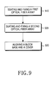
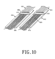
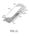
- step 530 for aligning the block base and the cover to each other the cover 640 is positioned on the block base 610 in alignment with the block base 610. As shown, in Figs. 11 and 12, the cover 640 shown in Fig. 10 is turned over and then aligned on the block base 610.
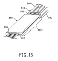
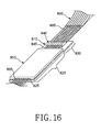
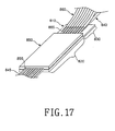
- the second optical fiber array 865 is inserted into eight cavities which are formed on an input end of the multi-core optical fiber block. As shown in Figs. 16 and 17, the second optical fiber array 865 is inserted through the input end of the multi-core optical fiber block until the leading end of the second optical fiber array 865 passes through the even cavities of the sixteen cavities formed on an output end of the multi-core optical fiber block. In this insertion process, the second optical fiber array 865 is inserted during a sliding movement on the first ribbon type optical fiber cable 840.
- the second optical fiber array 865 is seated in the even grooves of the first groove array 825 formed on the output end of the block base 810.
Landscapes
- Physics & Mathematics (AREA)
- General Physics & Mathematics (AREA)
- Optics & Photonics (AREA)
- Mechanical Coupling Of Light Guides (AREA)
- Optical Couplings Of Light Guides (AREA)
Abstract
Description
To reduce bending of the first and second de-sheathed multi-core
Claims (13)
- A block base having a groove array to allow an optical fiber array to be seated in the groove array, the groove array comprising:first sub-grooves having a depth and a pitch decreasing from an input end of the block base to an output end of the block base; and,second sub-grooves formed alternately between the first sub-grooves and having a depth and a pitch increasing from the input end of the block base to the output end of the block base.
- The block base according to claim 1, further comprising:a body formed with the groove array on a top surface thereof; and,a support extending from the body and having a thickness substantially less than that of the body.
- A multi-core optical fiber block having groove arrays, comprising:a block base formed with a first tree-structured groove array on a top surface thereof to allow an optical fiber array to be seated in the first groove array; and,a cover formed with a second tree-structured groove array on a bottom surface thereof and aligned with the block base to cover the optical fiber array.
- The multi-core optical fiber block according to claim 3, wherein the block base comprises:a body formed with the first tree-structured groove array on the top surface thereof; and,a support extending from the body and having a thickness substantially less than that of the body.
- The multi-core optical fiber block according to claim 3, wherein the cover further includes a support extending from the body and having a thickness substantially smaller than that of the body.
- A method for aligning a multi-core optical fiber block having groove arrays, the method comprising the steps of:(a) aligning a first optical fiber array on a block base having a tree-structured groove array;(b) aligning a cover having a tree-structured groove array with the block base to cover the first optical fiber array, thus forming a plurality of cavities therebetween; and,(c) inserting a second optical fiber array into the cavities formed between the first optical fiber array and the cover.
- The method according to claim 6, wherein the step (a) of aligning the first optical fiber array further comprises the step of aligning the first optical fiber array on odd number grooves of the tree-structure groove array.
- The method according to claim 6, wherein the step (b) of inserting the second optical fiber array further comprises the step of inserting the second optical fiber array through even number grooves of the tree-structure groove array.
- A method for aligning a multi-core optical fiber block having groove arrays, the method comprising the steps of:(a) aligning a first optical fiber array on a first block having a first tree-structured groove array;(b) aligning a second optical fiber array on a second block having a second tree-structure groove array; and(c) aligning the second black with the first block base to cover the first optical fiber array.
- The method according to claim 9, wherein the step (a) of aligning the first optical fiber array further comprises the step of applying epoxy resin along a predetermined position of the first optical fiber array.
- The method according to claim 9, wherein the step (a) of aligning the first optical fiber array further comprises the step of aligning the first optical fiber array on odd number grooves of the first tree-structure groove array.
- The method according to claim 9, wherein the step (b) of aligning the second optical fiber array further comprises the step of applying epoxy resin along a predetermined position of the second optical fiber array.
- The method according to claim 9, wherein the step (b) of aligning the second optical fiber array further comprises the step of aligning the second optical fiber array on even number grooves of the first tree-structure groove array.
Applications Claiming Priority (2)
| Application Number | Priority Date | Filing Date | Title |
|---|---|---|---|
| KR2002006057 | 2002-02-02 | ||
| KR10-2002-0006057A KR100446505B1 (en) | 2002-02-02 | 2002-02-02 | Block with grooves having tree structure and multicore optical fiber block using it and method for aligning the multicore optical fiber block |
Publications (3)
| Publication Number | Publication Date |
|---|---|
| EP1338908A2 true EP1338908A2 (en) | 2003-08-27 |
| EP1338908A3 EP1338908A3 (en) | 2004-07-14 |
| EP1338908B1 EP1338908B1 (en) | 2006-03-22 |
Family
ID=36217551
Family Applications (1)
| Application Number | Title | Priority Date | Filing Date |
|---|---|---|---|
| EP03002141A Expired - Lifetime EP1338908B1 (en) | 2002-02-02 | 2003-01-31 | Block base having tree-structured groove array, multi-core optical fiber block having tree-structured groove arrays, and method for aligning optical fiber arrays in the same |
Country Status (5)
| Country | Link |
|---|---|
| US (1) | US7103256B2 (en) |
| EP (1) | EP1338908B1 (en) |
| JP (1) | JP3723180B2 (en) |
| KR (1) | KR100446505B1 (en) |
| DE (1) | DE60304071T2 (en) |
Cited By (3)
| Publication number | Priority date | Publication date | Assignee | Title |
|---|---|---|---|---|
| WO2005040879A1 (en) * | 2003-10-16 | 2005-05-06 | 3M Innovative Properties Company | Optical interconnect device |
| WO2013151582A1 (en) * | 2012-04-05 | 2013-10-10 | Nanoprecision Products, Inc. | High density multi-fiber for optical fiber connector |
| WO2013124256A3 (en) * | 2012-02-21 | 2013-12-05 | Ldt Laser Display Technology Gmbh | Projection head for a laser projector |
Families Citing this family (18)
| Publication number | Priority date | Publication date | Assignee | Title |
|---|---|---|---|---|
| JP4301245B2 (en) * | 2003-11-17 | 2009-07-22 | 住友金属鉱山株式会社 | Optical fiber array |
| JP4848773B2 (en) * | 2006-01-06 | 2011-12-28 | リコープリンティングシステムズ株式会社 | MULTI-BEAM LIGHT SOURCE, MANUFACTURING METHOD THEREOF, OPTICAL SCANNING DEVICE AND IMAGE FORMING DEVICE USING THE MULTI-BEAM LIGHT SOURCE |
| JP5135513B2 (en) * | 2008-02-20 | 2013-02-06 | 並木精密宝石株式会社 | Optical fiber array |
| US20110123160A1 (en) * | 2009-11-24 | 2011-05-26 | Moshe Liberman | Dual floor densed fiber optic array |
| TWI490575B (en) * | 2010-12-14 | 2015-07-01 | Hon Hai Prec Ind Co Ltd | Optical fiber coupling connector |
| TW201321812A (en) * | 2011-11-22 | 2013-06-01 | Hon Hai Prec Ind Co Ltd | Optical fiber coupling assembly and male optical connector thereof |
| KR101462719B1 (en) * | 2012-05-31 | 2014-11-17 | 삼성전기주식회사 | COIL COMPONENT, ELECTRIONIC DEVICE AND PoE SYSTEM HAVING THE SAME |
| WO2014174333A1 (en) * | 2013-04-23 | 2014-10-30 | Fci | Ferrule for an optical connector |
| AU2015318357B2 (en) | 2014-09-19 | 2021-05-27 | CommScope Connectivity Belgium BVBA | Optical fiber connection system including optical fiber alignment device |
| KR20160071810A (en) * | 2014-12-12 | 2016-06-22 | (주)파이버프로 | Polarization maintain fiber array block and manufacturing method of the same |
| US10663665B2 (en) * | 2017-11-30 | 2020-05-26 | Corning Research & Development Corporation | Ribbon handling device for fusion splicer and methods of fusion splicing |
| EP3807684B1 (en) * | 2018-06-15 | 2024-09-18 | Corning Incorporated | High-density optical fiber ribbon and ribbon cable interconnects employing small diameter optical fibers |
| WO2021076649A1 (en) * | 2019-10-15 | 2021-04-22 | Ayar Labs, Inc. | Multi-chip packaging of silicon photonics |
| US10908362B1 (en) * | 2019-10-16 | 2021-02-02 | International Business Machines Corporation | Interlacing boot for two-row ferrule ribbon for one dimensional photonic chip beach front |
| US11500160B2 (en) * | 2020-05-29 | 2022-11-15 | Corning Research & Development Corporation | Multicore optical fiber fan-out assemblies and apparatuses |
| KR20230152042A (en) * | 2021-03-10 | 2023-11-02 | 스미토모 덴코 옵티프론티어 가부시키가이샤 | Optical fiber holder and optical fiber core wire connection method |
| CN218995720U (en) * | 2022-09-23 | 2023-05-09 | 苏州天孚光通信股份有限公司 | Substrate for optical fiber array |
| CN121794603A (en) * | 2023-08-30 | 2026-04-03 | 康宁研究与开发公司 | Fiber Optic Converter |
Family Cites Families (33)
| Publication number | Priority date | Publication date | Assignee | Title |
|---|---|---|---|---|
| US2537044A (en) * | 1946-11-29 | 1951-01-09 | Hydrocarbon Research Inc | Continuous method of producing oxygen involving the use of a thermophore and the purging thereof |
| FR2376425A1 (en) * | 1976-12-31 | 1978-07-28 | Socapex | POSITIONING SLEEVE FOR CONNECTOR OF AN OPTICAL MONOFIBER, CONNECTOR CONTAINING SUCH A SLEEVE, AND PROCESS FOR IMPLEMENTATION OF SUCH SLEEVE |
| DE2938224A1 (en) | 1979-09-21 | 1981-04-09 | Siemens AG, 1000 Berlin und 8000 München | OPTICAL DEVICE FOR CONTACTLESS WRITING |
| DE2938301A1 (en) * | 1979-09-21 | 1981-04-09 | Siemens AG, 1000 Berlin und 8000 München | OPTICAL DEVICE FOR CONTACTLESS WRITING, IN PARTICULAR FOR FACSIMILE RETURN OF IMAGES AND TEXT |
| US4405207A (en) | 1981-01-12 | 1983-09-20 | Xerox Corporation | Method of assembling a gradient index lens array having reduction properties |
| JPS59224812A (en) | 1983-06-06 | 1984-12-17 | Nippon Sheet Glass Co Ltd | Optical transmitter array |
| DE3476279D1 (en) * | 1983-08-08 | 1989-02-23 | Alliance Tech Ind | Process for joining optical fibres, and optical splice obtained |
| US4784456A (en) * | 1987-05-06 | 1988-11-15 | E. I. Du Pont De Nemours And Company | Fiber optic connector |
| US4880494A (en) | 1988-10-07 | 1989-11-14 | Eastman Kodak Company | Method of making a fiber optic array |
| US4911526A (en) * | 1988-10-07 | 1990-03-27 | Eastman Kodak Company | Fiber optic array |
| US4923275A (en) * | 1988-10-07 | 1990-05-08 | Eastman Kodak Company | Fiber optic array |
| US4991930A (en) * | 1989-11-22 | 1991-02-12 | Eastman Kodak Company | Fiber optic array |
| US5109460A (en) * | 1991-08-23 | 1992-04-28 | Eastman Kodak Company | Optical fiber array for a thermal printer and method of making same |
| JPH07249798A (en) * | 1994-03-09 | 1995-09-26 | Fujitsu Ltd | Optical component fixing device and manufacturing method thereof |
| JP3198039B2 (en) | 1996-01-12 | 2001-08-13 | 日立電線株式会社 | Optical fiber array component and method of manufacturing the same |
| JPH1010352A (en) | 1996-06-18 | 1998-01-16 | Hitachi Cable Ltd | Fiber array and manufacturing method thereof |
| JPH10213721A (en) * | 1997-01-30 | 1998-08-11 | Yazaki Corp | Optical fiber array ferrule and method of manufacturing the same |
| FR2760538B1 (en) * | 1997-03-05 | 1999-05-21 | France Telecom | INTEGRATED DUPLEXER MULTIPLEXER SPLITTER DEVICE FOR MULTI-CORE FIBERS |
| JPH11326704A (en) | 1998-03-19 | 1999-11-26 | Ngk Insulators Ltd | Optical fiber array and its production |
| JPH11344640A (en) * | 1998-03-31 | 1999-12-14 | Ngk Insulators Ltd | Glass substrate and its two-stage forming method |
| JP3111978B2 (en) * | 1998-05-15 | 2000-11-27 | 日本電気株式会社 | High precision mounting structure of optical fiber |
| JP3968543B2 (en) | 1998-09-03 | 2007-08-29 | 住友電気工業株式会社 | Manufacturing method of optical fiber array |
| JP2000275477A (en) * | 1999-03-23 | 2000-10-06 | Minolta Co Ltd | Optical-fiber array |
| US6366720B1 (en) * | 1999-07-09 | 2002-04-02 | Chiaro Networks Ltd. | Integrated optics beam deflector assemblies utilizing side mounting blocks for precise alignment |
| US6421493B1 (en) * | 2000-03-24 | 2002-07-16 | Fitel Usa Corp. | Apparatus and method for assembling and aligning a plurality of optical fibers |
| CA2350187A1 (en) | 2000-07-25 | 2002-01-25 | Hung Viet Ngo | Optical fiber connector |
| JP3722353B2 (en) * | 2000-07-26 | 2005-11-30 | 日本電信電話株式会社 | Optical fiber array device and waveguide type multilayer optical wave circuit module using the same |
| CA2325424A1 (en) * | 2000-11-07 | 2002-05-07 | Zenastra Photonics Inc. | Method for preparing optical fibers for connection to other fibers or to planar waveguides and device for such connection |
| US20030021572A1 (en) * | 2001-02-07 | 2003-01-30 | Steinberg Dan A. | V-groove with tapered depth and method for making |
| WO2002075413A1 (en) * | 2001-03-16 | 2002-09-26 | Zolo Technologies, Inc. | Optical fiber pigtail assembly |
| US6965721B1 (en) * | 2001-04-18 | 2005-11-15 | Tullis Barclay J | Integrated manufacture of side-polished fiber optics |
| US6535685B1 (en) * | 2001-07-19 | 2003-03-18 | Barclay J. Tullis | Arcuate fiber routing using stepped grooves |
| JP2004184676A (en) * | 2002-12-03 | 2004-07-02 | Japan Aviation Electronics Industry Ltd | Alignment member for optical fiber array and optical fiber array manufactured using the same |
-
2002
- 2002-02-02 KR KR10-2002-0006057A patent/KR100446505B1/en not_active Expired - Fee Related
-
2003
- 2003-01-28 JP JP2003018350A patent/JP3723180B2/en not_active Expired - Fee Related
- 2003-01-30 US US10/354,348 patent/US7103256B2/en not_active Expired - Lifetime
- 2003-01-31 EP EP03002141A patent/EP1338908B1/en not_active Expired - Lifetime
- 2003-01-31 DE DE60304071T patent/DE60304071T2/en not_active Expired - Fee Related
Cited By (6)
| Publication number | Priority date | Publication date | Assignee | Title |
|---|---|---|---|---|
| WO2005040879A1 (en) * | 2003-10-16 | 2005-05-06 | 3M Innovative Properties Company | Optical interconnect device |
| US7186031B2 (en) | 2003-10-16 | 2007-03-06 | 3M Innovative Properties Company | Optical interconnect device |
| WO2013124256A3 (en) * | 2012-02-21 | 2013-12-05 | Ldt Laser Display Technology Gmbh | Projection head for a laser projector |
| WO2013151582A1 (en) * | 2012-04-05 | 2013-10-10 | Nanoprecision Products, Inc. | High density multi-fiber for optical fiber connector |
| US9507099B2 (en) | 2012-04-05 | 2016-11-29 | Nanoprecision Products, Inc. | High density multi-fiber ferrule for optical fiber connector |
| RU2630201C2 (en) * | 2012-04-05 | 2017-09-06 | Нанопресижен Продактс, Инк. | Coupling for fiber connector with high density of placing full set of fibers |
Also Published As
| Publication number | Publication date |
|---|---|
| KR20030065961A (en) | 2003-08-09 |
| EP1338908A3 (en) | 2004-07-14 |
| US20030169995A1 (en) | 2003-09-11 |
| US7103256B2 (en) | 2006-09-05 |
| KR100446505B1 (en) | 2004-09-04 |
| DE60304071D1 (en) | 2006-05-11 |
| JP2003227966A (en) | 2003-08-15 |
| DE60304071T2 (en) | 2007-04-12 |
| EP1338908B1 (en) | 2006-03-22 |
| JP3723180B2 (en) | 2005-12-07 |
Similar Documents
| Publication | Publication Date | Title |
|---|---|---|
| EP1338908B1 (en) | Block base having tree-structured groove array, multi-core optical fiber block having tree-structured groove arrays, and method for aligning optical fiber arrays in the same | |
| RU2589445C2 (en) | Fibre-optic tape and fibre-optic cable, in which there is fibre-optic tape | |
| CN102681119B (en) | Optical fiber cable and optical fiber ribbon | |
| JP5235125B2 (en) | Optical fiber tape and optical fiber cable | |
| US7445832B2 (en) | Ribboned polarization-maintaining fiber and manufacturing method therefor, and polarization-maintaining optical fiber array using the same | |
| US6795634B2 (en) | Optical fiber block having holding sub-block | |
| US6345916B1 (en) | Fiber optic connector and its manufacturing method | |
| US6478473B1 (en) | Multiple-fiber optical connector, and method for assembling the same | |
| JP3772929B2 (en) | Optical fiber holding component and optical fiber array | |
| JP7271226B2 (en) | Optical fiber array manufacturing unit, manufacturing apparatus and manufacturing method | |
| US20030156814A1 (en) | Optical fiber block having semicircular grooves and method for same | |
| JPH08122577A (en) | Multi-core small-diameter fiber connector, fiber insertion aid used for making the same, and method for making multi-core small-diameter fiber connector | |
| CN119376048A (en) | A prefabricated butterfly-shaped lead-in optical cable | |
| US20020076167A1 (en) | Multiple-fiber optical connector, and method for assembling the same | |
| JPH0522205B2 (en) | ||
| JPH095576A (en) | Multi-fiber optical transmission body terminal part | |
| JP3968543B2 (en) | Manufacturing method of optical fiber array | |
| KR100259267B1 (en) | Splicer for optical fiber | |
| JP2003066264A (en) | Narrow pitch optical fiber array | |
| JP3916047B2 (en) | Optical fiber array | |
| KR100584115B1 (en) | Optical splitter and its manufacturing method | |
| JPH0915456A (en) | Fixing method of multi-core optical fiber cord | |
| JPH09230158A (en) | Array structure of optical fiber | |
| KR100407372B1 (en) | Optical fiber array | |
| JPH11109162A (en) | Optical fiber array |
Legal Events
| Date | Code | Title | Description |
|---|---|---|---|
| PUAI | Public reference made under article 153(3) epc to a published international application that has entered the european phase |
Free format text: ORIGINAL CODE: 0009012 |
|
| 17P | Request for examination filed |
Effective date: 20030131 |
|
| AK | Designated contracting states |
Designated state(s): AT BE BG CH CY CZ DE DK EE ES FI FR GB GR HU IE IT LI LU MC NL PT SE SI SK TR |
|
| AX | Request for extension of the european patent |
Extension state: AL LT LV MK RO |
|
| PUAL | Search report despatched |
Free format text: ORIGINAL CODE: 0009013 |
|
| AK | Designated contracting states |
Kind code of ref document: A3 Designated state(s): AT BE BG CH CY CZ DE DK EE ES FI FR GB GR HU IE IT LI LU MC NL PT SE SI SK TR |
|
| AX | Request for extension of the european patent |
Extension state: AL LT LV MK RO |
|
| RIC1 | Information provided on ipc code assigned before grant |
Ipc: 7G 02B 6/38 B Ipc: 7G 02B 6/36 A |
|
| 17Q | First examination report despatched |
Effective date: 20050204 |
|
| AKX | Designation fees paid |
Designated state(s): DE FR GB |
|
| GRAP | Despatch of communication of intention to grant a patent |
Free format text: ORIGINAL CODE: EPIDOSNIGR1 |
|
| GRAS | Grant fee paid |
Free format text: ORIGINAL CODE: EPIDOSNIGR3 |
|
| GRAA | (expected) grant |
Free format text: ORIGINAL CODE: 0009210 |
|
| AK | Designated contracting states |
Kind code of ref document: B1 Designated state(s): DE FR GB |
|
| REG | Reference to a national code |
Ref country code: GB Ref legal event code: FG4D |
|
| REF | Corresponds to: |
Ref document number: 60304071 Country of ref document: DE Date of ref document: 20060511 Kind code of ref document: P |
|
| ET | Fr: translation filed | ||
| PLBE | No opposition filed within time limit |
Free format text: ORIGINAL CODE: 0009261 |
|
| STAA | Information on the status of an ep patent application or granted ep patent |
Free format text: STATUS: NO OPPOSITION FILED WITHIN TIME LIMIT |
|
| 26N | No opposition filed |
Effective date: 20061227 |
|
| PG25 | Lapsed in a contracting state [announced via postgrant information from national office to epo] |
Ref country code: DE Free format text: LAPSE BECAUSE OF NON-PAYMENT OF DUE FEES Effective date: 20070801 |
|
| GBPC | Gb: european patent ceased through non-payment of renewal fee |
Effective date: 20070131 |
|
| REG | Reference to a national code |
Ref country code: FR Ref legal event code: ST Effective date: 20070930 |
|
| PG25 | Lapsed in a contracting state [announced via postgrant information from national office to epo] |
Ref country code: GB Free format text: LAPSE BECAUSE OF NON-PAYMENT OF DUE FEES Effective date: 20070131 |
|
| PG25 | Lapsed in a contracting state [announced via postgrant information from national office to epo] |
Ref country code: FR Free format text: LAPSE BECAUSE OF NON-PAYMENT OF DUE FEES Effective date: 20070131 |