EP1338899A1 - Fault diagnosis circuit for LED indicating light - Google Patents
Fault diagnosis circuit for LED indicating light Download PDFInfo
- Publication number
- EP1338899A1 EP1338899A1 EP02007790A EP02007790A EP1338899A1 EP 1338899 A1 EP1338899 A1 EP 1338899A1 EP 02007790 A EP02007790 A EP 02007790A EP 02007790 A EP02007790 A EP 02007790A EP 1338899 A1 EP1338899 A1 EP 1338899A1
- Authority
- EP
- European Patent Office
- Prior art keywords
- circuit
- current
- led indicating
- comparing
- signal
- Prior art date
- Legal status (The legal status is an assumption and is not a legal conclusion. Google has not performed a legal analysis and makes no representation as to the accuracy of the status listed.)
- Withdrawn
Links
- 238000003745 diagnosis Methods 0.000 title claims abstract description 23
- 230000000717 retained effect Effects 0.000 claims description 10
- 238000010586 diagram Methods 0.000 description 6
- 230000005856 abnormality Effects 0.000 description 4
- 238000000034 method Methods 0.000 description 4
- 239000003086 colorant Substances 0.000 description 1
- 239000004020 conductor Substances 0.000 description 1
- 239000012634 fragment Substances 0.000 description 1
- 230000006870 function Effects 0.000 description 1
- 208000012978 nondisjunction Diseases 0.000 description 1
- 230000008447 perception Effects 0.000 description 1
- 239000004065 semiconductor Substances 0.000 description 1
Images


Classifications
-
- G—PHYSICS
- G09—EDUCATION; CRYPTOGRAPHY; DISPLAY; ADVERTISING; SEALS
- G09G—ARRANGEMENTS OR CIRCUITS FOR CONTROL OF INDICATING DEVICES USING STATIC MEANS TO PRESENT VARIABLE INFORMATION
- G09G3/00—Control arrangements or circuits, of interest only in connection with visual indicators other than cathode-ray tubes
- G09G3/20—Control arrangements or circuits, of interest only in connection with visual indicators other than cathode-ray tubes for presentation of an assembly of a number of characters, e.g. a page, by composing the assembly by combination of individual elements arranged in a matrix no fixed position being assigned to or needed to be assigned to the individual characters or partial characters
- G09G3/22—Control arrangements or circuits, of interest only in connection with visual indicators other than cathode-ray tubes for presentation of an assembly of a number of characters, e.g. a page, by composing the assembly by combination of individual elements arranged in a matrix no fixed position being assigned to or needed to be assigned to the individual characters or partial characters using controlled light sources
- G09G3/30—Control arrangements or circuits, of interest only in connection with visual indicators other than cathode-ray tubes for presentation of an assembly of a number of characters, e.g. a page, by composing the assembly by combination of individual elements arranged in a matrix no fixed position being assigned to or needed to be assigned to the individual characters or partial characters using controlled light sources using electroluminescent panels
- G09G3/32—Control arrangements or circuits, of interest only in connection with visual indicators other than cathode-ray tubes for presentation of an assembly of a number of characters, e.g. a page, by composing the assembly by combination of individual elements arranged in a matrix no fixed position being assigned to or needed to be assigned to the individual characters or partial characters using controlled light sources using electroluminescent panels semiconductive, e.g. using light-emitting diodes [LED]
-
- G—PHYSICS
- G09—EDUCATION; CRYPTOGRAPHY; DISPLAY; ADVERTISING; SEALS
- G09G—ARRANGEMENTS OR CIRCUITS FOR CONTROL OF INDICATING DEVICES USING STATIC MEANS TO PRESENT VARIABLE INFORMATION
- G09G3/00—Control arrangements or circuits, of interest only in connection with visual indicators other than cathode-ray tubes
- G09G3/006—Electronic inspection or testing of displays and display drivers, e.g. of LED or LCD displays
-
- G—PHYSICS
- G01—MEASURING; TESTING
- G01R—MEASURING ELECTRIC VARIABLES; MEASURING MAGNETIC VARIABLES
- G01R31/00—Arrangements for testing electric properties; Arrangements for locating electric faults; Arrangements for electrical testing characterised by what is being tested not provided for elsewhere
- G01R31/50—Testing of electric apparatus, lines, cables or components for short-circuits, continuity, leakage current or incorrect line connections
Definitions
- the present invention relates to a fault diagnosis circuit allowing a fault diagnosis in an indicating light having an LED indicator, such as a signal indicating light, a character display panel, a signal, and a fire alarm.
- an LED indicator such as a signal indicating light, a character display panel, a signal, and a fire alarm.
- Indicating lights have been provided to lines and machine and equipment in factories to indicate an operation status, an abnormality, a fault, etc. of the lines and equipment.
- LED an element that emits light by flowing a current through a PN junction of a semiconductor
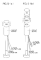
- Fig. 5 shows perspective views of the LED indicating lights.
- Fig. 5(a) shows a single-stage type having an indicator in one stage
- Fig. 5(b) shows a multi-stage type having indicators stacked in more than one stage.
- the multi-stage type can emit light in more than one color, which allows a current status to be judged by color discrimination of emitted light.
- the above method of constantly flowing a minimal current cannot be adapted to the LED indicating light, because the LED turns ON with such a minimal current.
- a fault diagnosis circuit for an LED indicating light of the present invention includes: an LED indicating unit; a pulse generating circuit; a current detecting circuit for detecting a flowing current by flowing a pulse of a current through the LED indicating unit based on pulses generated by the pulse generating circuit; a comparing circuit for comparing a current value detected by the current detecting circuit with a threshold value to judge a disconnection; a retaining circuit for generating a signal and retaining the signal when the current value is judged as being smaller than the threshold value as a result of a comparison by the comparing circuit; and an output circuit for outputting a disconnection notifying signal based on the signal retained by the retaining circuit.
- a fault diagnosis circuit for an LED indicating light of the present invention includes: an LED indicating unit; a pulse generating circuit; a current detecting circuit for detecting a flowing current by flowing a pulse of a current through the LED indicating unit based on pulses generated by the pulse generating circuit; a comparing circuit for comparing a current value detected by the current detecting circuit with a threshold value to judge a short-circuit; a retaining circuit for generating a signal and retaining the signal when the current value is judged as being larger than the threshold value as a result of a comparison by the comparing circuit; and an output circuit for outputting a short-circuit notifying signal based on the signal retained by the retaining circuit.
- the manager can diagnose a fault in the LED indicating unit by checking a notification output without perceiving the turning ON of the LED.
- a fault diagnosis circuit for an LED indicating light of the present invention includes: an LED indicating unit; a pulse generating circuit; a current detecting circuit for detecting a flowing current by flowing a pulse of a current through the LED indicating unit based on pulses generated by the pulse generating circuit; a first comparing circuit for comparing a current value detected by the current detecting circuit with a first threshold value to judge a disconnection; a second comparing circuit for comparing the current value detected by the current detecting circuit with a second threshold value to judge a short-circuit; a retaining circuit for generating a signal and retaining the signal when the current value is judged as being larger than the first threshold value to judge the disconnection and smaller than the second threshold value to judge the short-circuit as a result of comparisons by the first and second comparing circuits; and an output circuit for outputting a normality notifying signal based on the signal retained by the retaining circuit.
- the manager can diagnose a normality in the LED indicating unit by checking a notification output without perceiving the turning ON of the LED.
- the notification output is outputted constantly. Hence, the manager can check the notification output anytime.
- Fig. 1 is a circuit diagram showing an LED indicating light 2 and its fault diagnosis circuit 1.
- the LED indicating light 2 is provided with an outside direct current power source 4, an outside contact 5, and indicating units stacked in multiple stages 3a, 3b, and so forth each enclosing a plurality of LEDs.
- the colors of light emitted from the LEDs in the indicating units in the respective stages 3a, 3b, and so forth may be the same or different.
- the LEDs in any of the stages 3a, 3b, and so forth are allowed to emit light by switching the outside contact 5 depending on an operation status of the lines or machine and equipment in the factory.
- the terminals at the lower potential in the LEDs in the respective stages 3a, 3b, and so forth are connected to the collector terminal of a transistor Q1 through a resistor R1 by way of an automatic selection switch 6 provided in the fault diagnosis circuit 1. Also, these terminals are connected to comparing circuits 8 and 9 by way of the automatic selection switch 6.
- the base terminal of the transistor Q1 periodically receives pulses of a constant width generated from a pulse generating circuit 7.
- the comparing circuit 8 compares an input voltage V with a threshold value E1 while the pulses of a constant width are generated, and when the voltage V is lower than the threshold value E1, it outputs an output at a constant level. The output is retained by a retaining circuit 10 until the following pulse is inputted.
- the comparing circuit 9 compares the input voltage V with another threshold value E2 (E1 ⁇ E2) while the pulses of a constant width are generated, and when the voltage V is higher than the threshold value E2, it outputs an output at a constant level. The output is retained by another retaining circuit 11 until the following pulse is inputted.
- the threshold value E2 is set at a level that an occurrence of a short-circuit is likely from experiences and the threshold value E1 is set at a level that an occurrence of a disconnection is likely from experiences, so that a short-circuit is judged when the voltage V is higher the threshold value E2 and a disconnection is judged when the voltage V is lower than the threshold value E1.
- the pulses of a constant width are generated from the pulse generating circuit 7, an LED in any of the stages 3a, 3b, and so forth turns ON.
- the pulse width may be set to 100 microseconds or less.
- FIG. 3 is a detailed circuit diagram of a fault diagnosis circuit for judging a short-circuit and a disconnection.
- Fig. 3 shows a circuit for diagnosing only one stage in the LED indicating light, which means it is a fault diagnosis circuit corresponding to an LED indicating light of the single-stage type having an indicator in one stage as shown in Fig. 5(a).
- a special-purpose IC20 (NE555) is used for pulse generation.
- a pulse signal of a predetermined cycle (for example, every 5 seconds) can be obtained by using the IC20.
- the resistor R1 and the transistor Q1 function in the same manner as were described with reference to Fig. 1.
- operational amplifiers 21 and 22 and logical circuits 23 and 24 are used as the comparing circuits.
- the threshold value E1 and the threshold value E2 are generated by resistors R2, R3, and R4. When a voltage V at one end of the resistor R1 is higher than the threshold E2, the operational amplifier 21 outputs a high-level output, and when the voltage V is higher than the threshold value E1, the operational amplifier 22 also outputs a high-level output.
- Wiring is installed in such a manner that the logical product (AND) circuit 23 receives outputs from both the operational amplifiers 21 and 22 as inputs, and that the non-disjunction (NOR) circuit 24 also receives outputs from both the operational amplifiers 21 and 22 as inputs.
- an output from the AND circuit 23 is latched by a D-type latch circuit 25 until the following pulse signal is inputted, and the result is indicated by an indicating light 27.
- an output from the NOR circuit 24 is latched by a D-type latch circuit 26 until the following pulse signal is inputted, and the result is indicated by an indicating light 28.
- Fig. 4 is a detailed circuit diagram showing another fault diagnosis circuit.
- Fig. 4 also shows a circuit for diagnosing only one stage in the LED indicating light, and it should be appreciated that a circuit having a switch for switching LEDs in multiple stages (see Reference Numeral 6 in Fig. 1) may be adopted in order to correspond to an LED indicating light of the multi-stage type having indicators stacked in more than one stage.
- This circuit uses operational amplifiers 21 and 22 and logical circuits 31, 32, and 33 as the comparing circuits.
- the threshold value E1 and the threshold value E2 are generated by resistors R2, R3, and R4.
- the operational amplifier 21 When a voltage V at the resistor R1 is higher than the threshold value E2, the operational amplifier 21 outputs a high-level output, and when the voltage V at the resistor R1 is higher than the threshold E1, the operational amplifier 22 also outputs a high-level output.
- Wiring is installed in such a manner that the non-conjunction (NAND) circuit 31 receives outputs from both the operational amplifiers 21 and 22 as inputs, and that the logical sum (OR) circuit 32 also receives outputs from both the operational amplifiers 21 and 22 as inputs.
- NAND non-conjunction
- OR logical sum
- An output from the NAND circuit 31 and an output from the OR circuit 32 are inputted into the AND circuit 33, and the AND circuit 33 outputs a signal only when the output from the NAND circuit 31 and the output from the OR circuit 32 are both at a high level, that is, in the status of (2) above.
- the outputted signal is latched by a D-type latch circuit 34 until the following signal is inputted, and the result is indicated by an indicating light 35.
- the diagnosis result may be notified by a buzzer, an alarm, a data output, etc.
Landscapes
- Engineering & Computer Science (AREA)
- Physics & Mathematics (AREA)
- General Physics & Mathematics (AREA)
- Computer Hardware Design (AREA)
- Theoretical Computer Science (AREA)
- Testing Of Short-Circuits, Discontinuities, Leakage, Or Incorrect Line Connections (AREA)
- Circuit Arrangement For Electric Light Sources In General (AREA)
- Led Devices (AREA)
- Non-Portable Lighting Devices Or Systems Thereof (AREA)
- Illuminated Signs And Luminous Advertising (AREA)
Abstract
Description
- The present invention relates to a fault diagnosis circuit allowing a fault diagnosis in an indicating light having an LED indicator, such as a signal indicating light, a character display panel, a signal, and a fire alarm.
- Indicating lights have been provided to lines and machine and equipment in factories to indicate an operation status, an abnormality, a fault, etc. of the lines and equipment.
- Some of the recent indicating lights adopt a light emitting diode (LED: an element that emits light by flowing a current through a PN junction of a semiconductor)(hereinafter, referred to as the LED indicting light).
- Fig. 5 shows perspective views of the LED indicating lights. Fig. 5(a) shows a single-stage type having an indicator in one stage, and Fig. 5(b) shows a multi-stage type having indicators stacked in more than one stage. The multi-stage type can emit light in more than one color, which allows a current status to be judged by color discrimination of emitted light.
- When the LED indicating light fails, the status of the lines or equipment cannot be judged, and therefore, it is necessary to monitor the occurrence of an abnormality in the indicator of the LED indicating light.
- There has been known a technique of detecting a disconnection in a lamp or a disconnection in the indicator by constantly flowing a minimal current too small to turn ON the lamp (see Japanese Laid-open Utility Model No. 5-038703 (1993)). However, this technique is intended for lamps having filaments.
- The above method of constantly flowing a minimal current cannot be adapted to the LED indicating light, because the LED turns ON with such a minimal current.
- It is therefore an object of the present invention to achieve a circuit allowing a fault diagnosis in the LED indicating light while making the turning ON of the LED unperceivable by human sense.
- A fault diagnosis circuit for an LED indicating light of the present invention includes: an LED indicating unit; a pulse generating circuit; a current detecting circuit for detecting a flowing current by flowing a pulse of a current through the LED indicating unit based on pulses generated by the pulse generating circuit; a comparing circuit for comparing a current value detected by the current detecting circuit with a threshold value to judge a disconnection; a retaining circuit for generating a signal and retaining the signal when the current value is judged as being smaller than the threshold value as a result of a comparison by the comparing circuit; and an output circuit for outputting a disconnection notifying signal based on the signal retained by the retaining circuit.
- A fault diagnosis circuit for an LED indicating light of the present invention includes: an LED indicating unit; a pulse generating circuit; a current detecting circuit for detecting a flowing current by flowing a pulse of a current through the LED indicating unit based on pulses generated by the pulse generating circuit; a comparing circuit for comparing a current value detected by the current detecting circuit with a threshold value to judge a short-circuit; a retaining circuit for generating a signal and retaining the signal when the current value is judged as being larger than the threshold value as a result of a comparison by the comparing circuit; and an output circuit for outputting a short-circuit notifying signal based on the signal retained by the retaining circuit.
- According to each of the above arrangements, because a pulse of a current is flown through the LED indicating unit, even when an LED emits light, it becomes difficult to perceive emitted light by sight. The pulse of the current is compared with the threshold value, and the comparison result is retained and outputted as a notification. Hence, the manager can diagnose a fault in the LED indicating unit by checking a notification output without perceiving the turning ON of the LED.
- A fault diagnosis circuit for an LED indicating light of the present invention includes: an LED indicating unit; a pulse generating circuit; a current detecting circuit for detecting a flowing current by flowing a pulse of a current through the LED indicating unit based on pulses generated by the pulse generating circuit; a first comparing circuit for comparing a current value detected by the current detecting circuit with a first threshold value to judge a disconnection; a second comparing circuit for comparing the current value detected by the current detecting circuit with a second threshold value to judge a short-circuit; a retaining circuit for generating a signal and retaining the signal when the current value is judged as being larger than the first threshold value to judge the disconnection and smaller than the second threshold value to judge the short-circuit as a result of comparisons by the first and second comparing circuits; and an output circuit for outputting a normality notifying signal based on the signal retained by the retaining circuit.
- According to this arrangement, because a pulse of a current is flown through the LED indicating unit, even when an LED emits light, it becomes difficult to perceive emitted light by sight. The pulse of the current is compared with the threshold values, and the comparison result is retained and outputted as a notification. Hence, the manager can diagnose a normality in the LED indicating unit by checking a notification output without perceiving the turning ON of the LED.
- When it is arranged in such a manner that the pulse generating circuit generates pulses repetitively and the retaining circuit retains the signal during a pulse repetition cycle, the notification output is outputted constantly. Hence, the manager can check the notification output anytime.
- It is preferable to set a time width of the pulse of the current flown through the LED indicating unit too short to perceive light emitted from an LED by sight.
- In the following, embodiments of the present invention will be described in detail with reference to the accompanying drawings.
-
- Fig. 1 is a circuit diagram depicting an
LED indicating light 2 and its fault diagnosis circuit 1; - Fig. 2 is a graph showing a relation between a voltage V, which is converted from a current flowing through LEDs in each stage, and threshold values;
- Fig. 3 is a detailed circuit diagram depicting a fault diagnosis circuit for diagnosing a short-circuit and a disconnection;
- Fig. 4 is a detailed circuit diagram depicting a fault diagnosis circuit for outputting indication during a normal operation; and
- Fig. 5 is a perspective view of LED indicating lights.
-
- Fig. 1 is a circuit diagram showing an
LED indicating light 2 and its fault diagnosis circuit 1. TheLED indicating light 2 is provided with an outside directcurrent power source 4, anoutside contact 5, and indicating units stacked inmultiple stages respective stages - The LEDs in any of the
stages outside contact 5 depending on an operation status of the lines or machine and equipment in the factory. - The terminals at the lower potential in the LEDs in the
respective stages automatic selection switch 6 provided in the fault diagnosis circuit 1. Also, these terminals are connected to comparingcircuits 8 and 9 by way of theautomatic selection switch 6. The base terminal of the transistor Q1 periodically receives pulses of a constant width generated from apulse generating circuit 7. - The comparing
circuit 8 compares an input voltage V with a threshold value E1 while the pulses of a constant width are generated, and when the voltage V is lower than the threshold value E1, it outputs an output at a constant level. The output is retained by aretaining circuit 10 until the following pulse is inputted. - The comparing circuit 9 compares the input voltage V with another threshold value E2 (E1 < E2) while the pulses of a constant width are generated, and when the voltage V is higher than the threshold value E2, it outputs an output at a constant level. The output is retained by another
retaining circuit 11 until the following pulse is inputted. - The following description will describe the method of setting the threshold value E1 and the threshold value E2. When a normal voltage is applied to an LED from the direct
current power source 4, if a too large current flows, it can be judged that the LED short-circuits or a short-circuit is occurring in an LED driving circuit (due to the mixing of conductor fragments, for example). If no current or a too small current flows, it can be judged that the LED is disconnected or an abnormality, such as a disconnection, is occurring in the LED driving circuit. - Hence, a current flown through the LEDs in each stage is converted to a voltage V, and as shown in Fig. 2, the threshold value E2 is set at a level that an occurrence of a short-circuit is likely from experiences and the threshold value E1 is set at a level that an occurrence of a disconnection is likely from experiences, so that a short-circuit is judged when the voltage V is higher the threshold value E2 and a disconnection is judged when the voltage V is lower than the threshold value E1.
- With the circuit of Fig. 1, it is possible to judge a short-circuit and a disconnection in each of the
stages LED indicating light 2 by checking an output voltage from each of theretaining circuits selection switch 6 one by one. It should be noted that the switching period of theselection switch 6 has to be longer than the pulse generation cycle of thepulse generating circuit 7. - While the pulses of a constant width are generated from the pulse generating
circuit 7, an LED in any of thestages LED indicating light 2. For example, the pulse width may be set to 100 microseconds or less. - Next, the following description will describe a more concrete example of the circuit. Fig. 3 is a detailed circuit diagram of a fault diagnosis circuit for judging a short-circuit and a disconnection.
- Fig. 3 shows a circuit for diagnosing only one stage in the LED indicating light, which means it is a fault diagnosis circuit corresponding to an LED indicating light of the single-stage type having an indicator in one stage as shown in Fig. 5(a).
- In order to correspond to an LED indicating light of the multi-stage type having indicators stacked in more than one stage as shown in Fig. 5(b), a circuit having a switch for switching LEDs in multiple stages (see
Reference Numeral 6 in Fig. 1) has to be adopted. - Referring to Fig. 3, a special-purpose IC20 (NE555) is used for pulse generation. A pulse signal of a predetermined cycle (for example, every 5 seconds) can be obtained by using the IC20.
- The resistor R1 and the transistor Q1 function in the same manner as were described with reference to Fig. 1.
- Herein,
operational amplifiers logical circuits operational amplifier 21 outputs a high-level output, and when the voltage V is higher than the threshold value E1, theoperational amplifier 22 also outputs a high-level output. - Wiring is installed in such a manner that the logical product (AND)
circuit 23 receives outputs from both theoperational amplifiers circuit 24 also receives outputs from both theoperational amplifiers - This arrangement results as follows: (1) when the voltage V at the resistor R1 is higher than the threshold value E2, the AND
circuit 23 is at a high level and the NORcircuit 24 is at a low level; (2) when the voltage V at the resistor R1 is not lower than the threshold value E1 and not higher than the threshold value E2, the ANDcircuit 23 is at a low level and the NORcircuit 24 is also at a low level; and (3) when the voltage V at the resistor R1 is lower than the threshold value E1, the ANDcircuit 23 is at a low level and the NORcircuit 24 is at a high level. It should be noted that the ANDcircuit 23 and the NORcircuit 24 will never be at a high level concurrently. - Subsequently, an output from the AND
circuit 23 is latched by a D-type latch circuit 25 until the following pulse signal is inputted, and the result is indicated by an indicatinglight 27. On the other hand, an output from the NORcircuit 24 is latched by a D-type latch circuit 26 until the following pulse signal is inputted, and the result is indicated by an indicatinglight 28. - As a consequence, anyone around can judge a short-circuit when the indicating
light 27 turns ON and a disconnection when the indicatinglight 28 turns ON. - Fig. 4 is a detailed circuit diagram showing another fault diagnosis circuit. Fig. 4 also shows a circuit for diagnosing only one stage in the LED indicating light, and it should be appreciated that a circuit having a switch for switching LEDs in multiple stages (see
Reference Numeral 6 in Fig. 1) may be adopted in order to correspond to an LED indicating light of the multi-stage type having indicators stacked in more than one stage. - This circuit uses
operational amplifiers logical circuits operational amplifier 21 outputs a high-level output, and when the voltage V at the resistor R1 is higher than the threshold E1, theoperational amplifier 22 also outputs a high-level output. - Wiring is installed in such a manner that the non-conjunction (NAND)
circuit 31 receives outputs from both theoperational amplifiers circuit 32 also receives outputs from both theoperational amplifiers - This arrangement results as follows: (1) when the voltage V at the resistor R1 is higher than the threshold value E2, the
NAND circuit 31 is at a low level and theOR circuit 32 is at a high level; (2) when the voltage V at the resistor R1 is not lower than the threshold value E1 and not higher than the threshold value E2, theNAND circuit 31 is at a high level and theOR circuit 32 is also at a high level; and (3) when the voltage V at the resistor R1 is lower than the threshold value E1, theNAND circuit 31 is at a high level and theOR circuit 32 is at a low level. It should be noted that theNAND circuit 31 and theOR circuit 32 will never be at a low level concurrently. - An output from the
NAND circuit 31 and an output from theOR circuit 32 are inputted into the ANDcircuit 33, and the ANDcircuit 33 outputs a signal only when the output from theNAND circuit 31 and the output from theOR circuit 32 are both at a high level, that is, in the status of (2) above. - The outputted signal is latched by a D-
type latch circuit 34 until the following signal is inputted, and the result is indicated by an indicatinglight 35. - Consequently, when the indicating
light 35 stays ON, anyone around can judge a normal status that neither a short-circuit nor a disconnection is occurring. When the indicatinglight 35 is turned OFF, anyone around can judge an abnormality, that is, either a short-circuit or a disconnection, is occurring in the indicator. - The above description described embodiments of the present invention. It should be appreciated, however, that the present invention is not limited to the foregoing. For example, instead of notifying the diagnosis result by the indicating
light 35, the diagnosis result may be notified by a buzzer, an alarm, a data output, etc. - The present invention can be modified in various manners within the scope of the invention.
Claims (5)
- A fault diagnosis circuit for an LED indicating light, characterized by:an LED indicating unit (3a, 3b, and so forth);a pulse generating circuit (7);a current detecting circuit (R1, Q1) for detecting a flowing current by flowing a pulse of a current through said LED indicating unit (3a, 3b, and so forth) based on pulses generated by said pulse generating circuit (7);a comparing circuit (8, 22) for comparing a current value detected by said current detecting circuit (R1, Q1) with a threshold value (E1) to judge a disconnection;a retaining circuit (10, 26) for generating a signal and retaining the signal when the current value is judged as being smaller than the threshold value (E1) as a result of a comparison by said comparing circuit (8, 22); andan output circuit (28) for outputting a disconnection notifying signal based on the signal retained by said retaining circuit (10, 26).
- A fault diagnosis circuit for an LED indicating light, characterized by:an LED indicating unit (3a, 3b, and so forth);a pulse generating circuit (7);a current detecting circuit (R1, Q1) for detecting a flowing current by flowing a pulse of a current through said LED indicating unit (3a, 3b, and so forth) based on pulses generated by said pulse generating circuit (7);a comparing circuit (9, 21) for comparing a current value detected by said current detecting circuit (R1, Q1) with a threshold value (E2) to judge a short-circuit;a retaining circuit (11, 25) for generating a signal and retaining the signal when the current value is judged as being larger than the threshold value (E2) as a result of a comparison by said comparing circuit (9, 21); andan output circuit (27) for outputting a short-circuit notifying signal based on the signal retained by said retaining circuit (11, 25).
- A fault diagnosis circuit for an LED indicating light, characterized by:an LED indicating unit (3a, 3b, and so forth);a pulse generating circuit (7);a current detecting circuit (R1, Q1) for detecting a flowing current by flowing a pulse of a current through said LED indicating unit (3a, 3b, and so forth) based on pulses generated by said pulse generating circuit (7);a first comparing circuit (22) for comparing a current value detected by said current detecting circuit (R1, Q1) with a first threshold value (E1) to judge a disconnection;a second comparing circuit (21) for comparing the current value detected by said current detecting circuit (R1, Q1) with a second threshold value (E2) to judge a short-circuit;a retaining circuit (34) for generating a signal and retaining the signal when the current value is judged as being larger than the first threshold value (E1) to judge the disconnection and smaller than the second threshold value (E2) to judge the short-circuit as a result of comparisons by said first and second comparing circuits (21, 22); andan output circuit (35) for outputting a normality notifying signal based on the signal retained by said retaining circuit (34).
- The fault diagnosis circuit for an LED indicating light according to Claim 1, 2, or 3, wherein:said pulse generating circuit (7) generates pulses repetitively; andsaid retaining circuit (10, 11, 25, 26, 34) retains the signal during a pulse repetition cycle.
- The fault diagnosis circuit for an LED indicating light according to any of Claims 1 through 4, wherein:a time width of the pulse of the current flown through said LED indicating unit (3a, 3b, and so forth) is set too short to perceive light emitted from an LED by sight.
Applications Claiming Priority (2)
| Application Number | Priority Date | Filing Date | Title |
|---|---|---|---|
| JP2002048318A JP2003249383A (en) | 2002-02-25 | 2002-02-25 | Failure diagnosis circuit for LED indicator |
| JP2002048318 | 2002-02-25 |
Publications (1)
| Publication Number | Publication Date |
|---|---|
| EP1338899A1 true EP1338899A1 (en) | 2003-08-27 |
Family
ID=27655441
Family Applications (1)
| Application Number | Title | Priority Date | Filing Date |
|---|---|---|---|
| EP02007790A Withdrawn EP1338899A1 (en) | 2002-02-25 | 2002-04-06 | Fault diagnosis circuit for LED indicating light |
Country Status (5)
| Country | Link |
|---|---|
| US (1) | US6888454B2 (en) |
| EP (1) | EP1338899A1 (en) |
| JP (1) | JP2003249383A (en) |
| KR (1) | KR20030070545A (en) |
| TW (1) | TW200303705A (en) |
Cited By (8)
| Publication number | Priority date | Publication date | Assignee | Title |
|---|---|---|---|---|
| EP1850139A1 (en) * | 2006-04-18 | 2007-10-31 | Macroblock Inc. | Method and apparatus for silent detection |
| EP2375397A1 (en) * | 2010-04-08 | 2011-10-12 | Havainne Oy | System and device for directing observation |
| AT511094B1 (en) * | 2011-03-25 | 2012-09-15 | Thales Austria Gmbh | ARRANGEMENT FOR STATE MONITORING OF A LAMP |
| CN104062532A (en) * | 2013-03-18 | 2014-09-24 | 艾尔瓦特集成电路科技(天津)有限公司 | Method and system used for detecting LED short circuit in LED strings or LED string matching |
| WO2016183903A1 (en) * | 2015-05-19 | 2016-11-24 | 深圳市华星光电技术有限公司 | Led backlight drive circuit |
| EP3252725A1 (en) * | 2016-05-31 | 2017-12-06 | Siemens Schweiz AG | Strobe notification appliance |
| CN107452305A (en) * | 2017-08-17 | 2017-12-08 | 西安易朴通讯技术有限公司 | A kind of current sensing means detected for screen, system and method |
| DE202019104171U1 (en) * | 2019-07-30 | 2020-11-04 | Tridonic Gmbh & Co Kg | driver |
Families Citing this family (40)
| Publication number | Priority date | Publication date | Assignee | Title |
|---|---|---|---|---|
| JP2005093196A (en) * | 2003-09-17 | 2005-04-07 | Moritex Corp | Illumination method, illumination device and parts thereof |
| KR100603760B1 (en) | 2004-12-17 | 2006-07-24 | 삼성전자주식회사 | Display device and driving pulse control method thereof |
| JP2006288945A (en) * | 2005-04-14 | 2006-10-26 | Pentax Corp | Endoscope voltage control circuit |
| US20070029555A1 (en) * | 2005-08-04 | 2007-02-08 | Lester Steven D | Edge-emitting LED light source |
| JP2007188692A (en) * | 2006-01-12 | 2007-07-26 | Denso Corp | Led lamp device |
| TWI299405B (en) * | 2006-03-02 | 2008-08-01 | Macroblock Inc | Method and apparatus for silent current detection |
| JP2007275212A (en) * | 2006-04-05 | 2007-10-25 | Ge Medical Systems Global Technology Co Llc | Light source device for endoscope and ultrasonograph with endoscope |
| WO2008061301A1 (en) * | 2006-11-20 | 2008-05-29 | Lednium Technology Pty Limited | A fault detector and a fault detection process for lighting |
| JP2009111035A (en) * | 2007-10-26 | 2009-05-21 | Panasonic Electric Works Co Ltd | Light emitting diode driving device, lighting device using light emitting diode driving device, vehicle interior lighting device, vehicle lighting device |
| TWI396468B (en) * | 2008-11-19 | 2013-05-11 | Inventec Corp | Light source circuit and electronic apparatus |
| US8044667B2 (en) * | 2009-04-20 | 2011-10-25 | Infineon Technologies Ag | Failure detection for series of electrical loads |
| JP5576638B2 (en) * | 2009-11-06 | 2014-08-20 | パナソニック株式会社 | Lighting device and headlight lighting device, headlight, vehicle using the same |
| CA2783320C (en) | 2009-12-09 | 2019-02-12 | Luminator Holding Lp | System and method for monitoring a signage system of a transit vehicle |
| DK2539879T3 (en) | 2010-02-25 | 2020-02-17 | Luminator Holding Lp | SYSTEM AND PROCEDURE FOR WIRELESS MANAGEMENT OF SIGNS |
| TWI430711B (en) * | 2010-07-05 | 2014-03-11 | 財團法人資訊工業策進會 | Light-emitting diode lighting fault detection system, light-emitting diode lighting fault detection method and computer readable recording medium for storing the same |
| EP2627158A1 (en) | 2010-10-08 | 2013-08-14 | Mitsubishi Chemical Corporation | Method of controlling illumination apparatus |
| US8558463B2 (en) | 2011-01-11 | 2013-10-15 | Panasonic Corporation | LED matrix open/short detection apparatus and method |
| EP2487999A1 (en) * | 2011-02-09 | 2012-08-15 | National Semiconductor Corporation | Technique for identifying at least one faulty light emitting diode in multiple strings of light emitting diodes |
| CN103018613A (en) * | 2011-09-21 | 2013-04-03 | 鸿富锦精密工业(深圳)有限公司 | Line detection module and testing jig provided with same |
| TWM431329U (en) * | 2012-01-10 | 2012-06-11 | Sirius Light Technology Co Ltd | Vehicle lamp status detection device |
| US8896319B2 (en) * | 2012-02-24 | 2014-11-25 | Richtek Technology Corporation | Light emitting device control circuit and short detection circuit thereof |
| TWI477788B (en) * | 2012-04-10 | 2015-03-21 | Realtek Semiconductor Corp | Apparatus and method of led short detection |
| TWI489906B (en) * | 2012-12-14 | 2015-06-21 | 英業達股份有限公司 | Controlling apparatus and light source apparatus |
| WO2014181423A1 (en) * | 2013-05-09 | 2014-11-13 | 株式会社パトライト | Signal display lamp and computer program for same |
| WO2014181425A1 (en) * | 2013-05-09 | 2014-11-13 | 株式会社パトライト | Signal display lamp |
| US9689930B2 (en) * | 2014-10-07 | 2017-06-27 | Infineon Technologies Ag | Single LED failure detection in a LED chain |
| US10475299B2 (en) | 2015-07-20 | 2019-11-12 | Banner Engineering Corporation | Modular indicator |
| US9997031B2 (en) | 2015-07-20 | 2018-06-12 | Banner Engineering Corporation | Modular indicator |
| EP3124988B1 (en) * | 2015-07-31 | 2019-02-20 | Siemens Mobility GmbH | Light emitting diode control circuit for a signal generator of an illuminating signal system |
| DE102015219903B4 (en) | 2015-10-14 | 2017-11-16 | Continental Automotive Gmbh | Method and circuit device for detecting a failure of at least one light emitting diode in a light emitting diode array |
| JP6697741B2 (en) * | 2016-08-26 | 2020-05-27 | パナソニックIpマネジメント株式会社 | Lighting device, lighting control system, lighting device, and vehicle |
| CN109884555B (en) * | 2017-12-06 | 2021-03-19 | 台达电子企业管理(上海)有限公司 | A DC centralized lighting system and a method for measuring the state of lamps and lanterns |
| US11495120B2 (en) * | 2018-04-10 | 2022-11-08 | Advancetrex Sensor Technologies Corp. | Universal programmable optic/acoustic signaling device with self-diagnosis |
| KR102100860B1 (en) * | 2018-12-03 | 2020-04-14 | 현대오트론 주식회사 | An Apparatus and A Method For Fail Diagnosis Lidar diode |
| US11039518B2 (en) * | 2018-12-18 | 2021-06-15 | Mtd Products Inc | Method for LED fault detection and mechanism having LED fault detection |
| CN112437522B (en) * | 2019-08-23 | 2024-04-09 | 华为技术有限公司 | Smart lights and smart light systems |
| JP7415389B2 (en) * | 2019-09-18 | 2024-01-17 | 株式会社デンソーウェーブ | Robot failure diagnosis device |
| KR102277688B1 (en) * | 2019-12-13 | 2021-07-15 | 현대모비스 주식회사 | Lidar device for vehicle and operation method thereof |
| CN114255693B (en) * | 2020-09-24 | 2023-06-20 | 华为技术有限公司 | Display device and repair method thereof, storage medium, display driver chip and device |
| JP2022109376A (en) | 2021-01-15 | 2022-07-28 | 三菱電機株式会社 | fire alarm system |
Citations (3)
| Publication number | Priority date | Publication date | Assignee | Title |
|---|---|---|---|---|
| DE3620584A1 (en) * | 1985-10-22 | 1987-04-23 | Nagema Veb K | Circuit for checking an LED display |
| EP0254804A2 (en) * | 1986-08-01 | 1988-02-03 | Tideland Signal Corporation | Electrical continuity sensing circuit |
| DE19516906A1 (en) * | 1995-05-09 | 1996-11-14 | Ind Automation Energiesysteme | Monitoring lamps supplied in parallel |
Family Cites Families (5)
| Publication number | Priority date | Publication date | Assignee | Title |
|---|---|---|---|---|
| JP2602133B2 (en) | 1991-08-06 | 1997-04-23 | 脩 薮崎 | Charger in wood vertical boring equipment |
| KR19990083648A (en) * | 1998-07-21 | 1999-12-06 | 최병석 | Fault detection circuit of all-optical display device and display state detection method using same |
| DE19852351A1 (en) * | 1998-11-13 | 2000-05-18 | Hella Kg Hueck & Co | Diagnostic system for an LED light in a motor vehicle |
| DE10115388A1 (en) * | 2001-03-28 | 2002-10-10 | Patent Treuhand Ges Fuer Elektrische Gluehlampen Mbh | Control circuit for an LED array |
| US7052180B2 (en) * | 2002-01-04 | 2006-05-30 | Kelvin Shih | LED junction temperature tester |
-
2002
- 2002-02-25 JP JP2002048318A patent/JP2003249383A/en active Pending
- 2002-04-06 EP EP02007790A patent/EP1338899A1/en not_active Withdrawn
-
2003
- 2003-01-28 US US10/352,810 patent/US6888454B2/en not_active Expired - Fee Related
- 2003-02-11 TW TW092102783A patent/TW200303705A/en unknown
- 2003-02-24 KR KR10-2003-0011278A patent/KR20030070545A/en not_active Withdrawn
Patent Citations (3)
| Publication number | Priority date | Publication date | Assignee | Title |
|---|---|---|---|---|
| DE3620584A1 (en) * | 1985-10-22 | 1987-04-23 | Nagema Veb K | Circuit for checking an LED display |
| EP0254804A2 (en) * | 1986-08-01 | 1988-02-03 | Tideland Signal Corporation | Electrical continuity sensing circuit |
| DE19516906A1 (en) * | 1995-05-09 | 1996-11-14 | Ind Automation Energiesysteme | Monitoring lamps supplied in parallel |
Cited By (13)
| Publication number | Priority date | Publication date | Assignee | Title |
|---|---|---|---|---|
| EP1850139A1 (en) * | 2006-04-18 | 2007-10-31 | Macroblock Inc. | Method and apparatus for silent detection |
| EP2375397A1 (en) * | 2010-04-08 | 2011-10-12 | Havainne Oy | System and device for directing observation |
| AT511094B1 (en) * | 2011-03-25 | 2012-09-15 | Thales Austria Gmbh | ARRANGEMENT FOR STATE MONITORING OF A LAMP |
| AT511094A4 (en) * | 2011-03-25 | 2012-09-15 | Thales Austria Gmbh | ARRANGEMENT FOR STATE MONITORING OF A LAMP |
| US9733314B2 (en) | 2013-03-18 | 2017-08-15 | Dialog Integrated Circuits (Tianjin) Limited | Method and system for detecting LED short circuit in LED strings or detecting matching among LED strings |
| CN104062532A (en) * | 2013-03-18 | 2014-09-24 | 艾尔瓦特集成电路科技(天津)有限公司 | Method and system used for detecting LED short circuit in LED strings or LED string matching |
| US10545195B2 (en) | 2013-03-18 | 2020-01-28 | Dialog Integrated Circuits (Tianjin) Limited | Method and system for detecting LED short circuit in LED strings or detecting matching among LED strings |
| WO2016183903A1 (en) * | 2015-05-19 | 2016-11-24 | 深圳市华星光电技术有限公司 | Led backlight drive circuit |
| EP3252725A1 (en) * | 2016-05-31 | 2017-12-06 | Siemens Schweiz AG | Strobe notification appliance |
| US10540885B2 (en) | 2016-05-31 | 2020-01-21 | Siemens Schweiz Ag | Fire alarm systems |
| CN107452305A (en) * | 2017-08-17 | 2017-12-08 | 西安易朴通讯技术有限公司 | A kind of current sensing means detected for screen, system and method |
| CN107452305B (en) * | 2017-08-17 | 2023-07-14 | 西安易朴通讯技术有限公司 | Current detection device, system and method for screen detection |
| DE202019104171U1 (en) * | 2019-07-30 | 2020-11-04 | Tridonic Gmbh & Co Kg | driver |
Also Published As
| Publication number | Publication date |
|---|---|
| JP2003249383A (en) | 2003-09-05 |
| TW200303705A (en) | 2003-09-01 |
| US20030160703A1 (en) | 2003-08-28 |
| US6888454B2 (en) | 2005-05-03 |
| KR20030070545A (en) | 2003-08-30 |
Similar Documents
| Publication | Publication Date | Title |
|---|---|---|
| US6888454B2 (en) | Fault diagnosis circuit for LED indicating light | |
| US6972674B2 (en) | Lighting device for vehicle | |
| US7301447B2 (en) | LED turn signal and error detecting method | |
| US7978089B2 (en) | Method and apparatus for ground fault detection | |
| WO2012077013A2 (en) | Control circuit for led lamps in automobile applications | |
| US6583731B2 (en) | Fault detection for traffic light systems using electronic lighting elements | |
| US4568923A (en) | Fire alarm system | |
| US4879739A (en) | Wiring test device and method | |
| US10939528B2 (en) | Electronic circuit with an LED module | |
| JP2009006981A (en) | Vehicle lighting | |
| US20030151418A1 (en) | Low voltage circuit tester | |
| GB2172456A (en) | A device for monitoring the operation of the lights circuit of a trailer of a commercial vehicle | |
| CA2512498A1 (en) | Hazard detector | |
| CN113291231B (en) | Running water lamp control system | |
| CN101743674B (en) | Circuit arrangement for fault indication | |
| JP4327437B2 (en) | Luminescent display device for displaying the operating status of the system and method for managing such a device, in particular for avionics | |
| US5877929A (en) | Break display apparatus for semiconductor switching element incorporating overcurrent/overheating protection function | |
| CN210835095U (en) | Fault detection circuit of automobile EPS system | |
| JP2001165986A (en) | Cable inspecting apparatus | |
| CN217902550U (en) | Traffic light fault real-time monitoring device | |
| CN220730371U (en) | Alarm circuit for detecting abnormal closing of normally closed end of relay | |
| CN216848191U (en) | Infrared light detection circuit and electronic equipment | |
| JP2008098495A (en) | LED failure detection device | |
| KR200266975Y1 (en) | A Sensor of the State of Circuit Breaker Operating Coil | |
| JP3121236B2 (en) | LED beacon light system |
Legal Events
| Date | Code | Title | Description |
|---|---|---|---|
| PUAI | Public reference made under article 153(3) epc to a published international application that has entered the european phase |
Free format text: ORIGINAL CODE: 0009012 |
|
| AK | Designated contracting states |
Designated state(s): AT BE CH CY DE DK ES FI FR GB GR IE IT LI LU MC NL PT SE TR |
|
| AX | Request for extension of the european patent |
Extension state: AL LT LV MK RO SI |
|
| 17P | Request for examination filed |
Effective date: 20040220 |
|
| AKX | Designation fees paid |
Designated state(s): AT BE CH CY DE DK ES FI FR GB GR IE IT LI LU MC NL PT SE TR |
|
| 17Q | First examination report despatched |
Effective date: 20050120 |
|
| GRAP | Despatch of communication of intention to grant a patent |
Free format text: ORIGINAL CODE: EPIDOSNIGR1 |
|
| STAA | Information on the status of an ep patent application or granted ep patent |
Free format text: STATUS: THE APPLICATION IS DEEMED TO BE WITHDRAWN |
|
| 18D | Application deemed to be withdrawn |
Effective date: 20070904 |